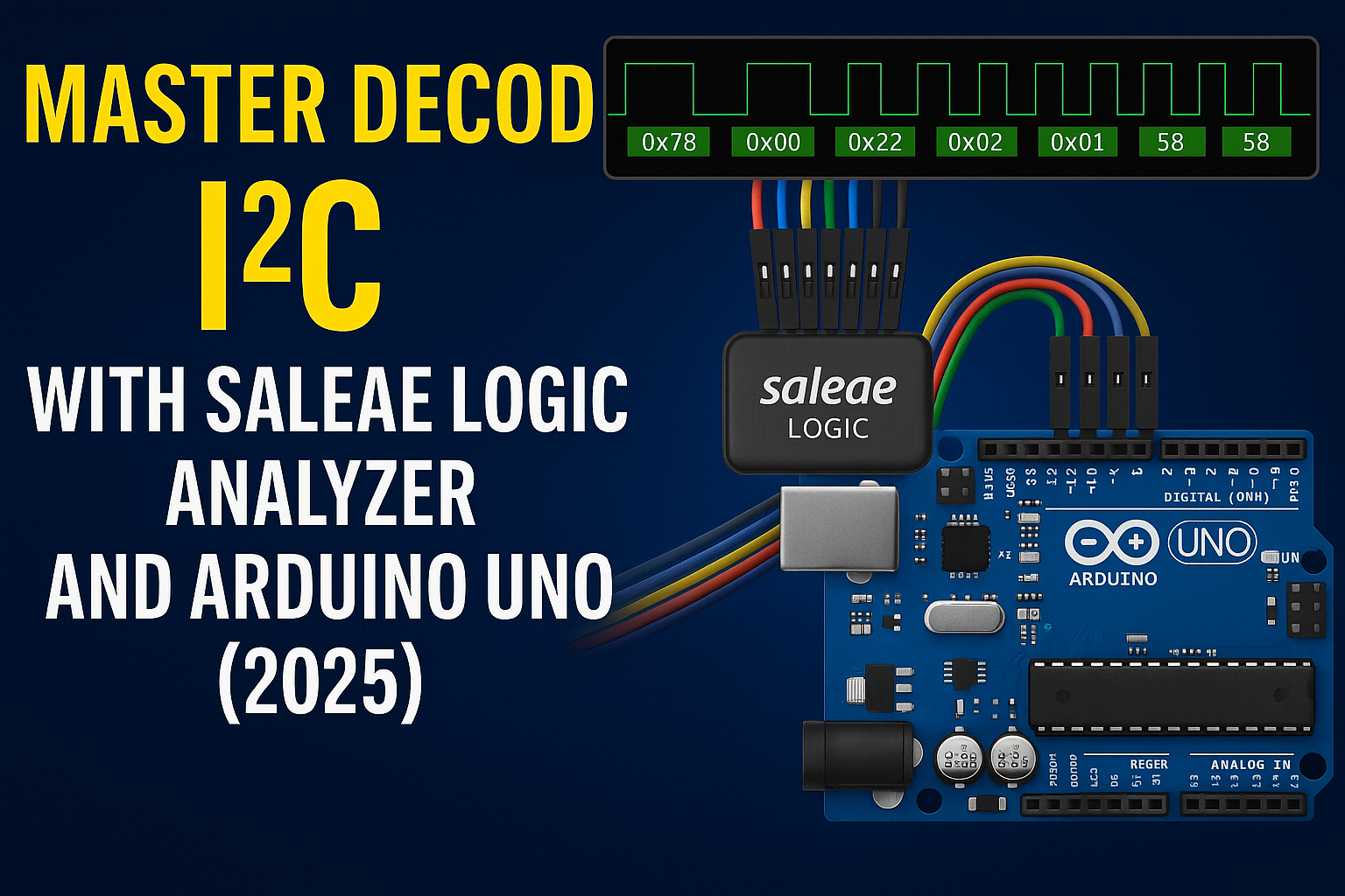
I²C with Saleae Logic Analyzer : I²C (Inter-Integrated Circuit) is a powerful two-wire communication protocol that allows multiple devices—such as sensors, displays, and memory modules—to communicate with a microcontroller like the Arduino using just SDA (Serial Data Line) and SCL (Serial Clock Line).
In this practical guide, you’ll learn how to decode, monitor, and debug I²C communication using the Saleae Logic Analyzer. Whether you’re dealing with an unresponsive OLED display or trying to understand data flow between your Arduino and I²C peripherals, this tutorial will help you visualize I²C signals, interpret data frames, and detect common issues—all with a user-friendly Saleae interface.
Perfect for beginners and embedded developers, this hands-on guide simplifies I²C debugging and gives you the confidence to troubleshoot any I²C-based project
Plan: Simulate I²C Using Arduino + ESP32 + Saleae
What You’ll Do:
- Connect Arduino Uno (Master) and ESP32 (Slave) via I²C.
- Upload I²C code to both devices.
- Monitor SDA and SCL lines with Saleae.
- Decode and analyze I²C protocol in the Saleae software.
+------------------+       +-----------------+       +-------------------------+
|    Arduino Uno   |       |     ESP32       |       |   Saleae Logic Analyzer |
|------------------|       |-----------------|       |-------------------------|
| A4 (SDA) --------+------>+ GPIO 21 (SDA)    |------>+ CH0                    |
| A5 (SCL) --------+------>+ GPIO 22 (SCL)    |------>+ CH1                    |
| GND ------------+-------+ GND              |------>+ GND                     |
+------------------+       +-----------------+       +-------------------------+
Code Part 1: Arduino Uno as I²C Master
#include <Wire.h>

void setup() {
  Wire.begin(); // I2C Master
  Serial.begin(9600);
  delay(1000);
}

void loop() {
  Serial.println("Sending data to ESP32...");
  Wire.beginTransmission(0x08);  // Slave address
  Wire.write("Hi");
  byte status = Wire.endTransmission();

  if (status == 0) {
    Serial.println("✅ ESP32 acknowledged the message!");
  } else {
    Serial.print("❌ Error sending to ESP32. Code: ");
    Serial.println(status);
  }

  delay(1000);
}
Code Part 2: ESP32 as I²C Slave
#include <Wire.h>

void receiveEvent(int bytes) {
  Serial.print("Received: ");
  while (Wire.available()) {
    char c = Wire.read();
    Serial.print(c);  // Show character
  }
  Serial.println();
}

void setup() {
  Serial.begin(115200);
  Wire.begin(0x08);  // ESP32 as Slave at address 0x08
  Wire.onReceive(receiveEvent);  // Set receive handler
}

void loop() {
  delay(100);
}
What You Need | I²C with Saleae Logic
- Arduino Uno
- ESP32 Dev Board
- Saleae Logic Analyzer
- Jumper Wires
- Arduino IDE
Wiring Between Arduino and ESP32
| Arduino Uno | ESP32 | Saleae Logic |
|---|---|---|
| A4 (SDA) | GPIO 21 (SDA) | CH0 (SDA) |
| A5 (SCL) | GPIO 22 (SCL) | CH1 (SCL) |
| GND | GND | GND |
Use Saleae Logic Analyzer
- Connect Channel 0 to SDA (A4/GPIO21), Channel 1 to SCL (A5/GPIO22), and GND.
- In the Saleae Logic software:
- Set sampling rate: 1MHz or higher
- Add I²C Analyzer (Channel 0 = SDA, Channel 1 = SCL)
- Hit Start, and observe the communication!
What You’ll See in Saleae
You’ll decode messages like:
[0x08] WRITE → 0x48 0x69Which corresponds to ASCII:
H i
" That’s the "Hi" sent from Arduino to ESP32 "
Tips & Gotchas
- If the ESP32 doesn’t show messages: check address match and wiring.
- Pull-up resistors (4.7kΩ) might be needed if you get unreliable signals.
- You can use
Wire.onReceive()on ESP32 to handle multiple bytes and print them.
You can also Visit other tutorials of Embedded Prep
- Master How to Use a Saleae Logic Analyzer with Arduino Uno (2025)
- I²C Debugging with Saleae Logic Analyzer Interview Questions
- Top 30+ I2C Interview Questions
- Bit Manipulation Interview Questions
- Structure and Union in c
- Fault Handling in Arm Cortex Mx Processor
- Merge sort algorithm
Special thanks to @mr-raj for contributing to this article on EmbeddedPrep
Mr. Raj Kumar is a highly experienced Technical Content Engineer with 7 years of dedicated expertise in the intricate field of embedded systems. At Embedded Prep, Raj is at the forefront of creating and curating high-quality technical content designed to educate and empower aspiring and seasoned professionals in the embedded domain.
Throughout his career, Raj has honed a unique skill set that bridges the gap between deep technical understanding and effective communication. His work encompasses a wide range of educational materials, including in-depth tutorials, practical guides, course modules, and insightful articles focused on embedded hardware and software solutions. He possesses a strong grasp of embedded architectures, microcontrollers, real-time operating systems (RTOS), firmware development, and various communication protocols relevant to the embedded industry.
Raj is adept at collaborating closely with subject matter experts, engineers, and instructional designers to ensure the accuracy, completeness, and pedagogical effectiveness of the content. His meticulous attention to detail and commitment to clarity are instrumental in transforming complex embedded concepts into easily digestible and engaging learning experiences. At Embedded Prep, he plays a crucial role in building a robust knowledge base that helps learners master the complexities of embedded technologies.