Category: 5G & Wireless Communications

  • Your ESP32 Deep-Sleep Battery Project May Be Wasting Power Here

    Your ESP32 Deep-Sleep Battery Project May Be Wasting Power Here

    Your ESP32 sketch may call deep sleep and still drain a battery far sooner than expected. The usual reason is that “the chip is asleep” and “the whole board is using almost no current” are not the same thing.

    In deep sleep, the ESP32 shuts down or clocks off parts of the chip, and wake-up sources can restart the application. But a development board also has a voltage regulator, USB-to-serial chip, power LED and sometimes sensors or displays. Any of those can draw current while the MCU sleeps. A sensor left powered or a network connection that takes longer than expected can dominate the average.

    Measure at the battery, not just in the datasheet

    Start by measuring current in series with the actual battery supply, with the exact board, regulator, sensors and firmware you intend to use. Capture both sleep current and the complete active cycle: boot, sensor warm-up, Wi-Fi association, transmission, retries and return to sleep. A multimeter that averages slowly can miss short current peaks; use an instrument or logger suited to the time scale and current range.

    Record the voltage and current over time. Then estimate average current using the full period, not just the low point between wake-ups. A current measurement taken directly at a bare module will not predict a finished product powered through a different regulator.

    A worked estimate—and its limits

    Suppose a project draws 100mA for two seconds once per minute and 10µA during the remaining 58 seconds. The simplified average is about 3.34mA: (100mA × 2/60) + (0.01mA × 58/60). A 2,000mAh battery divided by 3.34mA gives roughly 25 days in an ideal calculation.

    That is a planning estimate, not a runtime promise. It ignores regulator losses, battery capacity at the chosen load and temperature, self-discharge, Wi-Fi retries, startup variation and aging. Measure your own duty cycle and leave margin; battery chemistry and voltage conversion affect usable energy.

    Five places to look for hidden drain

    • Power LED: disable or remove it only if the board design permits and you understand the modification.
    • USB-to-serial interface: some dev boards keep this circuitry powered continuously.
    • Regulator quiescent current: a regulator can consume meaningful current even when the load is tiny; inspect its datasheet and measure the board.
    • Peripherals: switch sensors, displays and pull-up circuits off when appropriate, or choose parts with a real low-power mode.
    • Wake workload: reduce unnecessary scans and retries, send only the needed data, and verify that firmware actually enters sleep after every branch.

    Espressif’s ESP-IDF power-management documentation explains chip sleep modes and wake sources. The exact sleep current depends on chip configuration and board implementation, so do not apply a bare-chip value to a complete dev board without measurement.

    A practical test loop

    1. Measure baseline current with your board powered but the application idle.
    2. Measure deep-sleep current with the peripherals attached and then isolate them one by one.
    3. Log current through at least dozens of wake-and-send cycles, including weak Wi-Fi conditions.
    4. Estimate lifetime from average current and the battery’s usable capacity, then validate with a longer real-world run.

    Bottom line: Deep sleep is a firmware feature, not a battery-life guarantee. Measure the whole power path and the complete duty cycle before changing batteries or promising a service interval.

    Sources: ESP-IDF low-power mode overview; ESP-IDF sleep modes and wake-up sources.

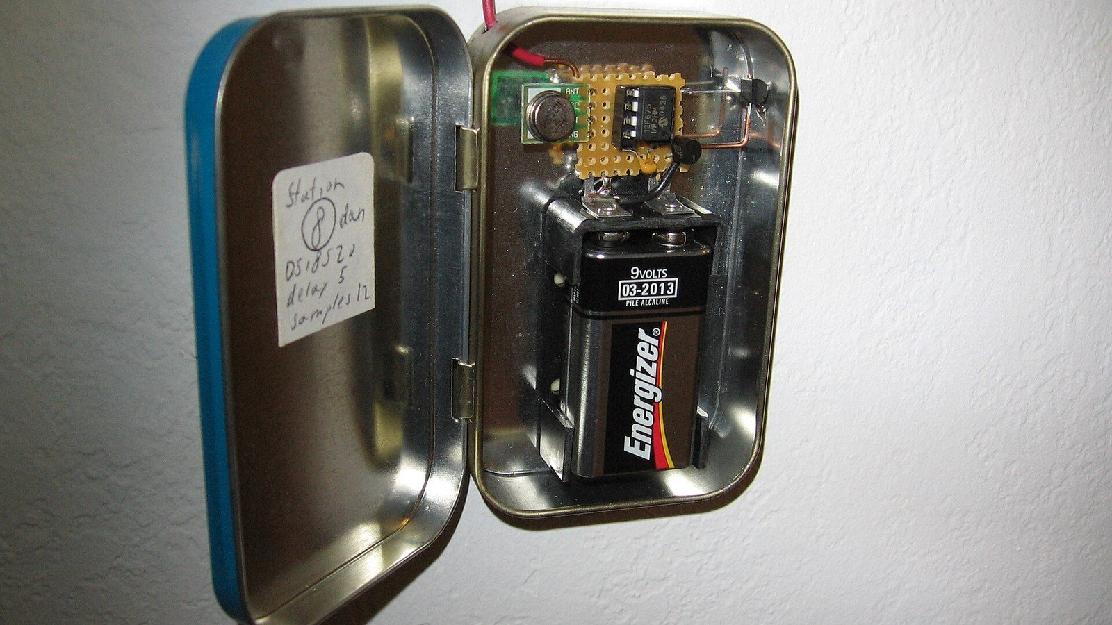
    Featured photo: Illustrative wireless temperature-sensor prototype by Micah Elizabeth Scott. Photo via Wikimedia Commons, licensed under CC BY-SA 2.0. The image was cropped and resized for this article.
  • ESP32-C5 Adds 5GHz Wi-Fi 6—but Will It Fix Your IoT Connection?

    ESP32-C5 Adds 5GHz Wi-Fi 6—but Will It Fix Your IoT Connection?

    If your IoT device struggles on a crowded 2.4GHz network, the ESP32-C5 has an unusual feature for this family: dual-band Wi-Fi 6, including both 2.4GHz and 5GHz. But the extra band does not automatically mean better range, lower power or faster real-world data in every room.

    Espressif lists the ESP32-C5 as a single-core RISC-V MCU running up to 240MHz, with 2.4GHz and 5GHz Wi-Fi 6, Bluetooth LE and 802.15.4 connectivity for protocols such as Thread and Zigbee. The chip has been in mass production since May 2025; development boards and module implementations have since broadened the ways makers can evaluate it.

    When 5GHz can help

    Wi-Fi at 5GHz can avoid some interference and congestion in a busy 2.4GHz environment. It can be a useful choice for a powered device close to an access point that moves images, updates or other larger payloads. Wi-Fi 6 features such as OFDMA and Target Wake Time can also be useful in supported network and device configurations.

    Those capabilities are not a promise that every router will schedule every IoT endpoint more efficiently. Device, access point, firmware and traffic pattern all matter. An 802.11ax label alone does not guarantee a measurable improvement for a simple sensor sending a few bytes.

    The trade-off: 5GHz is not a range upgrade

    Higher-frequency 5GHz signals generally lose strength more quickly through distance and obstacles than 2.4GHz signals. A sensor at the edge of a home may stay connected more reliably on 2.4GHz, even if that band is more crowded. A tiny antenna, enclosure, board layout and installation location can matter as much as the chip name.

    Also check region-specific radio rules and the exact module’s antenna design. A chip’s capabilities do not override a finished product’s certification, antenna restrictions or local regulations.

    ESP32-C5 versus ESP32-C6: the simple difference

    The key networking distinction is that C5 adds 5GHz Wi-Fi; C6 is a 2.4GHz Wi-Fi 6 platform with 802.15.4 and Bluetooth LE. Both can be relevant to connected-device designs, so choose by actual radio environment and ecosystem requirements—not by assuming the larger model number is always the right buy.

    For a Matter-over-Thread endpoint, compare the board’s supported stack, antenna, power design and certification path. For a Wi-Fi camera or image uploader, check throughput and memory requirements. For a tiny battery sensor, measure energy per full wake-and-send cycle before prioritising peak Wi-Fi capability.

    Before you switch boards

    1. Map the real install location and test signal strength through the actual walls and enclosure.
    2. Measure packet loss and reconnect behaviour on both bands with the intended router.
    3. Compare application-level latency and energy per message, not a headline PHY rate.
    4. Confirm ESP-IDF, module, antenna and certification support for your production design.

    Bottom line: ESP32-C5 is a meaningful option when 5GHz compatibility solves a demonstrated network constraint. It will not cure poor antenna placement, weak router coverage or a device that needs a low-power protocol instead of Wi-Fi.

    Sources: Espressif ESP32-C5 specifications; Espressif mass-production announcement; ESP-IDF Wi-Fi driver guide.

    Featured photo: Illustrative ESP32 development board by Edwiyanto; this is not an ESP32-C5 board. Photo via Wikimedia Commons, licensed under CC BY-SA 4.0. The image was cropped and resized for this article.

  • Next-Gen Test and Measurement Tools Drive High-Frequency, Multi-Domain Innovations (2026)

    As modern electronics continue pushing boundaries in speed and complexity, engineers face growing challenges in testing high-frequency and multi-domain systems. To meet these demands, leading players in the test and measurement industry are unveiling advanced solutions designed to address signal integrity, timing accuracy, and RF performance in one unified platform.

    The Rise of Multi-Domain Systems in 2025

    From 5G and Wi-Fi 7 to advanced radar and satellite communication systems, today’s technologies often involve multiple domains—digital, analog, RF, and optical—working together in real-time. As a result, traditional test methods are no longer sufficient. Engineers now require tools capable of synchronously analyzing multiple signal types across various time and frequency domains.

    What’s New in Test & Measurement?

    Recently, major T&M companies introduced solutions that offer unprecedented bandwidth, sampling rate, and resolution. These include:

    • High-Bandwidth Oscilloscopes with bandwidths exceeding 100 GHz, ideal for capturing ultra-fast transitions and jitter.
    • Mixed-Signal Analyzers capable of cross-domain correlation between RF and digital logic.
    • Real-Time Spectrum Analyzers featuring enhanced dynamic range and time-correlated capture.
    • Vector Network Analyzers (VNAs) designed for characterizing high-frequency passive and active components with precision.

    These tools are not just faster—they’re smarter. Many come equipped with AI-enhanced analysis, automated calibration, and intuitive user interfaces for faster setup and measurement accuracy.

    Why It Matters: Key Benefits

    • Improved Signal Integrity Testing: High-speed digital designs rely on accurate jitter, skew, and eye diagram measurements—now achievable with real-time correlation tools.
    • Faster Time-to-Market: Integrated platforms reduce the need for separate test equipment, speeding up the validation process.
    • Multi-Domain Insight: Engineers can visualize and debug interactions across RF, analog, and digital domains in one interface.
    • Enhanced 5G and mmWave Testing: With support for higher frequencies, these solutions ensure devices are compliant with the latest standards.

    Applications Driving the Demand

    • 5G/6G Communication Systems
    • Aerospace & Defense Radar
    • Automotive mmWave Sensors (ADAS)
    • Quantum Computing & Research
    • High-Speed Serial Interfaces (PCIe, USB4, DDR5)

    Future Outlook: Converging Domains, Unified Tools

    Looking forward, as domains continue to converge, test and measurement tools will evolve to become more integrated, cloud-connected, and software-defined. Test automation, AI-based diagnostics, and digital twin simulations are likely to redefine how hardware is validated in real-time.