
Explore Master Counters in Embedded Systems (2026): essential concepts, timers vs counters, interrupt integration, performance tips, and hands-on examples for microcontrollers.
Counters in Embedded Systems : Embedded systems form the backbone of many modern devices, from smartphones to household appliances. One crucial component of these systems is the counter. In this guide, we will explore the concept of counters in embedded systems, their purpose, how they work, and their practical applications in the real world.
What is a Counter in an Embedded System?
A counter in an embedded system is a digital component used to keep track of events, actions, or time. It’s essentially a variable that increments or decrements with every event, pulse, or clock cycle. Counters are widely used in embedded systems for a variety of purposes such as timekeeping, event counting, frequency measurement, and more.
Why Are Counters Important in Embedded Systems?
Counters are essential because they allow embedded systems to track and manage data over time. For instance, counters are commonly used to:
- Measure time: Keep track of time intervals for scheduling tasks.
- Count events: Record the number of occurrences of specific events.
- Control hardware: Control the state of various hardware components based on the counter’s value.
Types of Counters in Embedded Systems
There are several types of counters used in embedded systems, and each serves a different function. Let’s take a look at the main types:
1. Binary Counter
A binary counter is the most common type of counter in embedded systems. It stores the count in a binary format and increments or decrements the value with every clock cycle. The counter can be either up (incrementing) or down (decrementing).
Example: A binary counter could be used to count the number of button presses.
2. Decade Counter
A decade counter counts from 0 to 9 and then resets to 0. It is useful in applications where you need to count events in decimal format.
Example: A digital clock uses a decade counter to count seconds.
3. Up/Down Counter
An up/down counter can increment or decrement based on an external control signal. These counters are highly versatile because they can count both forward and backward.
Example: A counter in a reverse parking sensor can count the distance traveled backward.
4. Programmable Counter
A programmable counter allows you to set a specific threshold or count value at which it will reset or trigger an interrupt. These counters are flexible and can be adapted to different needs in embedded applications.
Example: A traffic light controller can use a programmable counter to time the switching of lights.
How Do Counters Work in Embedded Systems?
Counters typically work by utilizing a clock signal. The clock is a timing signal that determines when the counter should change its value. This can be a periodic signal, such as a timer interrupt, or an event-based signal, like a button press.
Here’s a basic explanation of how a counter works:
- Initialization: The counter is initialized to a starting value (typically 0).
- Clock or Event Trigger: Every time the clock signal or a specific event occurs, the counter either increments or decrements.
- Action at Threshold: If the counter reaches a predefined threshold, it can trigger an action like resetting the count, generating an interrupt, or performing a task.
Practical Applications of Counters in Embedded Systems
Counters have widespread usage in embedded systems. Some common practical applications include:
1. Timers and Clocks
In microcontrollers, counters are used to create accurate timers and clocks for controlling when specific actions occur. For example, a counter could be used to generate periodic interrupts for scheduling tasks in an RTOS (Real-Time Operating System).
2. Event Counting
Counters are used in applications where you need to count events, such as the number of items passed on a conveyor belt in an industrial process. This can help in quality control, production tracking, and automation.
3. Frequency Measurement
Counters are essential in measuring the frequency of an incoming signal. For example, an embedded system in a radio receiver can use a counter to determine the frequency of the received signal and process it accordingly.
4. PWM Generation
Pulse Width Modulation (PWM) signals are often generated using counters. The counter helps in controlling the duty cycle of the PWM signal to regulate the power delivered to devices like motors, LEDs, and heating elements.
5. Digital Clocks
Digital clocks are often implemented using decade counters, which are simple and efficient. The counters keep track of seconds, minutes, and hours, displaying them in the correct format.
Programming Counters in Embedded Systems
Counters in embedded systems can be programmed using low-level languages like C or assembly. Here’s a simple example of a counter in C for an embedded system:
#include

volatile int counter = 0;  // Declaring counter as volatile to ensure it's updated

void timer_interrupt_handler() {
    counter++;  // Increment counter every time the timer interrupt is triggered
    if (counter == 1000) {
        printf("Counter reached 1000!\n");
        counter = 0;  // Reset counter
    }
}

int main() {
    // Setup timer interrupt
    setup_timer_interrupt(timer_interrupt_handler);

    while(1) {
        // Main loop
    }

    return 0;
}
In this example, the counter increments every time the timer interrupt is triggered. Once the counter reaches 1000, it prints a message and resets.
The 8051 microcontroller has two 16-bit Timer/Counter modules:
- Timer 0
- Timer 1
Both can operate as either:
- Timers (based on the internal clock)
- Counters (based on external events)
These modules are incredibly useful in embedded systems for:
- Time delays
- Event counting
- Pulse generation
- Measuring signal durations
- Frequency measurements
Let’s understand each mode deeply.
Timer Mode (Internal Time Counting)
What is Timer Mode?
In Timer mode, the microcontroller uses its internal oscillator clock to increment the timer register. The CPU doesn’t do this manually — the timer is hardware-controlled and works independently.
For example: If your microcontroller has a 12 MHz clock, then each machine cycle = 1 µs (8051 takes 12 clock cycles for one machine cycle).
So, if the timer counts from 0 to 255 (8-bit), it takes:
256 × 1 µs = 256 µs
before it overflows.
This overflow can trigger an interrupt, which can be used to perform specific actions like toggling an LED, reading a sensor, etc.
Use Cases of Timer Mode:
- Creating accurate time delays.
- Generating baud rate for serial communication.
- Time-based task scheduling.
- Creating software timers for multitasking.
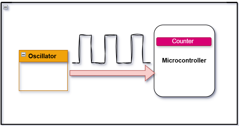
Counter Mode (External Event Counting)
What is Counter Mode?
In Counter mode, the timer is not counting time — instead, it is counting external events or pulses.
These events are fed through the T0 (P3.4) or T1 (P3.5) pins, depending on whether you’re using Timer 0 or Timer 1.
Example:
Suppose you have a sensor that outputs a pulse every time a person enters a room. You can connect that pulse to pin P3.4 (T0) and configure Timer 0 as a counter. The 8051 will increment the counter register every time it detects a falling or rising edge (depending on configuration).
Use Cases of Counter Mode:
- Counting number of items on a conveyor.
- Counting external signal pulses.
- Measuring frequency of a waveform.
- Speed sensors or encoder-based measurements.
Configuration: TMOD Register
The TMOD (Timer Mode) Register is an 8-bit register used to configure the mode of operation for Timer 0 and Timer 1.
TMOD Format:
| GATE | C/T | M1 | M0 | GATE | C/T | M1 | M0 |
   T1     T1   T1   T1    T0     T0   T0   T0
- GATE: When set, timer is controlled by an external pin. Usually set to 0 for software start/stop.
- C/T (Counter/Timer Select):
- 0: Timer Mode (uses internal clock)
- 1: Counter Mode (uses external pulse input)
- M1, M0: Select the mode of operation
- 00 – Mode 0 (13-bit Timer)
- 01 – Mode 1 (16-bit Timer)
- 10 – Mode 2 (8-bit auto-reload)
- 11 – Mode 3 (split timer mode or unused depending on timer)
Example:
To configure Timer 0 in Counter Mode, Mode 1 (16-bit):
TMOD = 0x05; // 00000101 in binary
- Lower nibble (00000101):
- GATE = 0 (ignore external control)
- C/T = 1 (Counter Mode)
- M1 M0 = 0 1 (Mode 1 → 16-bit)
Key Differences Between Timer and Counter
| Feature | Timer Mode | Counter Mode |
|---|---|---|
| Clock Source | Internal clock | External input pin (T0/T1) |
| Use Case | Delay generation, scheduling tasks | Counting pulses, measuring frequency |
| TMOD C/T Bit | 0 | 1 |
| Controlled By | System Clock | External hardware signal |
| Pins Used | None (internal operation) | T0 (P3.4), T1 (P3.5) |
| Typical Applications | Delay loops, baud rate gen | Event counters, frequency meter |
Practical Tip for Beginners
- If you’re building a digital stopwatch, use Timer mode.
- If you’re counting how many people passed through a door using a sensor, use Counter mode.
- Always set the TMOD register carefully — most bugs come from misconfiguring this!
How to Start in Keil (for Practice)
You can try this code to configure Timer 0 in Counter mode and read its value:
#include

void main() {
    TMOD = 0x05;     // Timer 0 as Counter, Mode 1 (16-bit)
    TL0 = 0x00;      // Clear low byte
    TH0 = 0x00;      // Clear high byte
    TR0 = 1;         // Start the counter

    while(1) {
        // Continuously check counter value
        // Display TL0, TH0 on LCD or Serial Monitor for observation
    }
}
Connect a pulse generator or button to P3.4 (T0 pin), and every press or pulse will increase the count.
| Concept | Summary |
|---|---|
| Timer Mode | Counts time using internal clock |
| Counter Mode | Counts events from outside sources |
| TMOD | Configures mode and type (timer/counter) |
| T0, T1 Pins | Used in Counter mode to receive pulses |
| Mode Types | Mode 0 (13-bit), Mode 1 (16-bit), Mode 2 (8-bit auto-reload), Mode 3 (split) |
Conclusion
Counters are a fundamental building block in embedded systems, enabling precise timekeeping, event tracking, and hardware control. Whether you’re measuring time, counting events, or generating signals, counters play a vital role in ensuring your embedded system performs its tasks effectively. By understanding how counters work and how to program them, you can enhance your embedded systems’ capabilities and achieve better control over your projects .
Interview Questions on Counters in Embedded Systems
Basic to Intermediate Questions
- What distinguishes a timer from a counter at the hardware level in microcontrollers like 8051?
- Why does a counter in 8051 count on falling edges instead of rising edges of external input signals?
- What is the role of the C/T bit in the TMOD register, and how does it influence timer vs counter operation?
- Why is Mode 2 in 8051 often referred to as the “auto-reload” mode, and what are its typical use cases?
- How does the THx and TLx register pair work together in 8051 timer/counter operations?
- How does using an external crystal oscillator (e.g., 11.0592 MHz) affect the accuracy of timing calculations?
- Can Timer 1 operate in Counter Mode while Timer 0 operates in Timer Mode in 8051? Explain how.
- Why is overflow handling critical in counter-based applications, and how can interrupts help?
- What is the maximum frequency that can be reliably counted using Timer 0 in Counter Mode?
- How do you ensure glitch-free pulse counting on external inputs in a noisy environment?
Advanced/Scenario-Based Questions
- Suppose you want to measure the RPM of a motor shaft using a sensor. How would you use 8051’s counter mode for that?
- If Timer 1 is running in Mode 1 and Timer 0 is in Mode 2 (Counter Mode), how would their operations differ?
- You have a push-button input connected to a counter pin. How would you prevent false triggering due to switch bounce?
- What are the limitations of 8051 timers in applications requiring long-duration delays? How can you overcome them?
- Describe a real-world use case where GATE-controlled counting is beneficial.
Practical/Code-Based Questions
- Write a code snippet in Embedded C to initialize Timer 0 in Counter Mode for counting external pulses up to 255.
- Develop a function in C that waits until Timer 0 overflows, then resets it and continues.
- Implement a C code logic to count 1000 pulses on T0 pin and light up an LED once the count is reached.
- Write ISR (Interrupt Service Routine) code for handling Timer 0 overflow in Counter Mode.
- Simulate an event logger using Timer 1 in Counter Mode that timestamps each pulse input.
You can also Visit other tutorials of Embedded Prep
- What is eMMC (Embedded MultiMediaCard) memory ?
- Top 30+ I2C Interview Questions
- Bit Manipulation Interview Questions
- Structure and Union in c
- Little Endian vs. Big Endian: A Complete Guide
- Merge sort algorithm
Special thanks to @embedded-prep for contributing to this article on Embedded Prep
Mr. Raj Kumar is a highly experienced Technical Content Engineer with 7 years of dedicated expertise in the intricate field of embedded systems. At Embedded Prep, Raj is at the forefront of creating and curating high-quality technical content designed to educate and empower aspiring and seasoned professionals in the embedded domain.
Throughout his career, Raj has honed a unique skill set that bridges the gap between deep technical understanding and effective communication. His work encompasses a wide range of educational materials, including in-depth tutorials, practical guides, course modules, and insightful articles focused on embedded hardware and software solutions. He possesses a strong grasp of embedded architectures, microcontrollers, real-time operating systems (RTOS), firmware development, and various communication protocols relevant to the embedded industry.
Raj is adept at collaborating closely with subject matter experts, engineers, and instructional designers to ensure the accuracy, completeness, and pedagogical effectiveness of the content. His meticulous attention to detail and commitment to clarity are instrumental in transforming complex embedded concepts into easily digestible and engaging learning experiences. At Embedded Prep, he plays a crucial role in building a robust knowledge base that helps learners master the complexities of embedded technologies.


1 thought on “Master Counters in Embedded Systems (2026)”