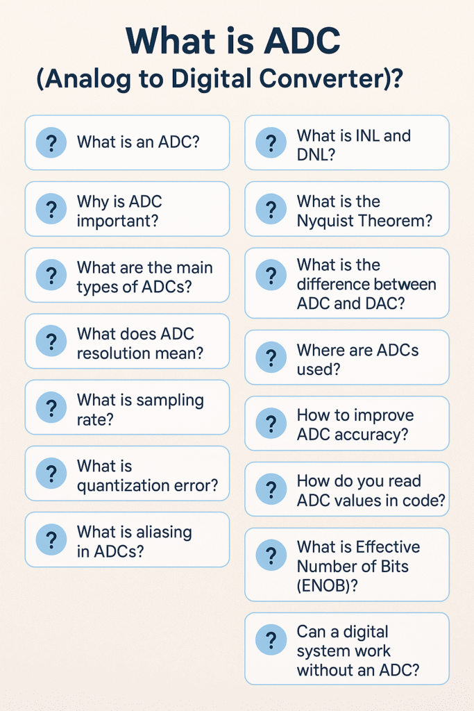
Introduction to ADC
An Analog to Digital Converter (ADC) is an essential electronic component that converts analog signals (continuous) into digital signals (discrete binary values). This is crucial because microcontrollers and computers can only process digital data.
Example: A temperature sensor gives analog voltage, but to display it on a digital screen or use it in calculations, it needs to be converted using an ADC.
Why is ADC Important?
- 🖥️ Microcontrollers can’t understand analog signals. ADC bridges this gap.
- 📷 Used in cameras, smartphones, IoT devices, and more.
- 🎧 Converts sound waves (analog) to digital for music players or voice assistants.
Types of ADC
- Flash ADC – Fastest, used in high-speed applications.
- Successive Approximation ADC (SAR) – Most common in microcontrollers.
- Dual Slope ADC – Used in digital multimeters.
- Sigma-Delta ADC – High resolution, used in audio and precision devices.
ADC Resolution Explained
Resolution means how finely the analog voltage is broken into steps.
| Resolution | Number of Levels | Example (5V reference) |
|---|---|---|
| 8-bit | 256 | 5V/256 = ~0.0195V/step |
| 10-bit | 1024 | 5V/1024 = ~0.00488V/step |
| 12-bit | 4096 | 5V/4096 = ~0.00122V/step |
Sampling Rate
The sampling rate is how many times per second the ADC samples the analog signal. It’s measured in samples per second (SPS) or Hz.
Higher sampling rate = more accurate representation of rapidly changing signals.
Common ADC Parameters to Know
| Term | Meaning |
|---|---|
| Input Range | Allowed voltage range (e.g., 0–3.3V) |
| Reference Voltage | Maximum voltage ADC compares to |
| Resolution | Number of bits |
| Sampling Rate | Frequency of reading |
| Accuracy | How close the digital output is to real analog value |
| Linearity | Straight-line behavior across input range |
ADC in Microcontrollers (Examples)
| Microcontroller | Built-in ADC? | Resolution | Channels |
|---|---|---|---|
| Arduino Uno (ATmega328P) | ✅ Yes | 10-bit | 6 |
| STM32F103 | ✅ Yes | 12-bit | 16 |
| ESP32 | ✅ Yes | 12-bit | 18 |
Steps to Use ADC in a Microcontroller
- Configure the ADC pin as input
- Set reference voltage (optional)
- Start ADC conversion
- Wait for conversion to complete
- Read the digital result
- Convert to voltage (if needed)
ADC to Voltage Conversion Formula
Voltage=(ADC Value2n−1)×Reference Voltage\text{Voltage} = \left(\frac{\text{ADC Value}}{2^n – 1}\right) \times \text{Reference Voltage}
Example (10-bit ADC, 5V ref, ADC value = 512): Voltage=5121023×5=≈2.5V\text{Voltage} = \frac{512}{1023} \times 5 = \approx 2.5V
Step-by-Step Working of Analog to Digital Converter
Sampling
- The ADC reads the analog input signal at regular intervals (sampling rate).
- It captures the signal’s voltage level at each moment.
- Sampling rate is measured in Hz or samples per second (SPS).
🔎 Example: If the sampling rate is 1000 Hz, it captures 1000 values per second.
Quantization
- The analog input is mapped into discrete steps based on the ADC’s resolution.
- Each range of voltage corresponds to a unique digital level.
For example, a 10-bit ADC with 5V reference splits the voltage into 1024 steps (~0.00488V each).
Encoding
- The quantized level is then converted into a binary number.
- This binary output is what the microcontroller uses.
Example: If the analog input is 2.5V, the 10-bit ADC gives a value of 512 (which is
0b1000000000in binary).
Working Formula
Digital Output=(Analog VoltageReference Voltage)×(2n−1)\text{Digital Output} = \left(\frac{\text{Analog Voltage}}{\text{Reference Voltage}}\right) \times (2^n – 1)
Where:
- n = number of bits of ADC (e.g., 10 for Arduino)
- Reference Voltage = maximum voltage ADC can handle (e.g., 5V)
Behind the Scenes (SAR ADC Example)
Most microcontrollers (like Arduino) use Successive Approximation Register (SAR) ADC. Here’s how it works internally:
- A sample-and-hold circuit captures and holds the input voltage.
- The SAR ADC uses a binary search method to find the digital value closest to the input.
- It starts from the MSB (Most Significant Bit) and moves to LSB (Least Significant Bit), adjusting with a comparator and DAC.
This allows fast and efficient conversion with minimal hardware.
Summary Table of Analog to Digital Converter
| Step | Process | Output |
|---|---|---|
| 1. Sampling | Takes voltage at regular intervals | Analog voltage snapshot |
| 2. Quantization | Assigns voltage to a level | Discrete step |
| 3. Encoding | Converts to binary | Digital value |
Configure the ADC (Analog to Digital Converter) in an STM32F407 MCU
To configure the ADC (Analog-to-Digital Converter) in an STM32F407 microcontroller, you can either do it directly via registers or use STM32CubeMX with HAL drivers. Below is a beginner-friendly guide using HAL (Hardware Abstraction Layer) in STM32CubeMX and also a bare-metal (register-level) method if you’re not using HAL.
Method 1: Using STM32CubeMX + HAL Library (Recommended for Beginners)
1. Open STM32CubeMX
- Create a new project for STM32F407VGTx (or your exact chip).
- Go to the “Pinout & Configuration” tab.
2. Enable ADC
- Click on the desired ADC input pin (e.g.,
PA0→ADC1_IN0). - This will automatically enable
ADC1.
3. Configure ADC Settings
Go to Peripherals > ADC1 and set:
- Resolution: 12 bits
- Scan Conversion Mode: Disabled (for single channel)
- Continuous Conversion Mode: Enabled (for continuous sampling)
- Data Alignment: Right
- DMA Continuous Requests: Optional (enable if using DMA)
In the “Channel Configuration” tab:
- Channel:
IN0 - Rank: 1
- Sampling Time: e.g.,
3 Cyclesor higher for accurate conversion
4. Generate Code
- Click Project > Generate Code
- Open the project in STM32CubeIDE
5. Code to Read ADC
Add this in main.c:
uint32_t adc_value;

HAL_ADC_Start(&hadc1);                        // Start ADC
HAL_ADC_PollForConversion(&hadc1, 100);       // Wait for conversion
adc_value = HAL_ADC_GetValue(&hadc1);         // Read value
HAL_ADC_Stop(&hadc1);                         // Stop ADC
Method 2: Bare-Metal (Direct Register Programming)
If you’re not using HAL or STM32Cube:
1. Enable Clocks
RCC->AHB1ENR |= RCC_AHB1ENR_GPIOAEN;   // Enable GPIOA clock
RCC->APB2ENR |= RCC_APB2ENR_ADC1EN;    // Enable ADC1 clock
2. Configure GPIOA Pin as Analog
GPIOA->MODER |= (3 << (0 * 2));        // PA0 as analog (MODER0[1:0] = 11)
GPIOA->PUPDR &= ~(3 << (0 * 2));       // No pull-up, pull-down
3. Configure ADC1
ADC1->SQR3 = 0;                        // Channel 0 (PA0)
ADC1->SMPR2 |= ADC_SMPR2_SMP0_0;      // Sample time (e.g., 15 cycles)
ADC1->CR2 |= ADC_CR2_ADON;           // Enable ADC
4. Start Conversion and Read Result
ADC1->CR2 |= ADC_CR2_SWSTART;         // Start conversion
while (!(ADC1->SR & ADC_SR_EOC));     // Wait for end of conversion
uint16_t result = ADC1->DR;           // Read value
Notes:
- ADC result is 12-bit (0–4095 for 3.3V reference)
- Voltage =
(ADC_value / 4095.0) * Vref
Performance of Analog to Digital Converter (ADCs)
The performance of Analog-to-Digital Converters (ADCs) is determined by several key factors that affect accuracy, speed, resolution, and overall signal fidelity. Here are the most important performance factors:
1. Resolution
- Definition: Number of bits used to represent the analog input.
- Impact: Higher resolution means finer granularity in signal representation.
- Example: A 12-bit ADC can represent 212=40962^{12} = 4096 levels.
2. Sampling Rate (Sampling Frequency)
- Definition: Number of samples the ADC takes per second (measured in samples per second or Hz).
- Impact: A higher sampling rate captures more detail in high-frequency signals (as per the Nyquist theorem).
- Example: Audio ADCs typically sample at 44.1 kHz or higher.
3. Signal-to-Noise Ratio (SNR)
- Definition: Ratio of the desired signal to background noise.
- Impact: A higher SNR means cleaner digital output.
- Related To: Resolution and noise characteristics of the ADC.
4. Total Harmonic Distortion (THD)
- Definition: A measure of distortion introduced by the ADC.
- Impact: Lower THD indicates better fidelity in signal reproduction.
5. Integral Non-Linearity (INL)
- Definition: Deviation of the actual transfer function from a straight line.
- Impact: Affects the overall accuracy across the entire input range.
6. Differential Non-Linearity (DNL)
- Definition: Deviation in step size between adjacent digital codes.
- Impact: High DNL can cause missing codes and reduced accuracy.
7. Effective Number of Bits (ENOB)
- Definition: A measure of ADC performance accounting for noise and distortion.
- Impact: Real-world indicator of usable resolution.
8. Conversion Time / Latency
- Definition: Time taken to complete one analog-to-digital conversion.
- Impact: Important in real-time applications.
9. Power Consumption
- Definition: Amount of power used by the ADC.
- Impact: Critical for battery-powered or embedded systems.
10. Input Bandwidth
- Definition: The frequency range over which the ADC can accurately sample.
- Impact: Determines the highest frequency the ADC can handle effectively.
Real-Life Examples of Analog to Digital Converter
- 🥵 Temperature monitoring using LM35 or DHT11
- 🔊 Audio signal processing in microphones
- 💡 Light detection using LDR
- 🧪 Chemical sensors (e.g., MQ135 gas sensor)
- ⚡ Battery voltage monitoring in IoT devices
Tips for Using Analog to Digital Converter Effectively
- Use a decoupling capacitor near the ADC pin for stability.
- Keep analog traces away from digital signals to reduce noise.
- Use averaging or filtering in code to smooth noisy signals.
- Match reference voltage to expected signal range for best accuracy.
Applications of Analog-to-Digital Converters (ADCs)
Analog-to-Digital Converters (ADCs) are crucial in modern electronics, enabling the interface between the analog real world and digital systems. Here are some key applications:
1. Audio and Speech Processing
- Use: Convert analog microphone signals to digital for processing, storage, and transmission.
- Examples: Smartphones, voice assistants, audio recorders.
2. Medical Devices
- Use: Digitize physiological signals like ECG, EEG, and blood pressure.
- Examples: Heart monitors, digital thermometers, medical imaging equipment.
3. Communication Systems
- Use: Convert analog RF signals to digital for modulation/demodulation and data processing.
- Examples: Software-defined radios, mobile phones, satellite communications.
4. Industrial Automation and Control
- Use: Read sensor data (temperature, pressure, flow) for control systems.
- Examples: PLCs, SCADA systems, robotics.
5. Data Acquisition Systems (DAQ)
- Use: Record and monitor physical signals in real time for analysis.
- Examples: Laboratory instrumentation, environmental monitoring.
6. Consumer Electronics
- Use: Interface analog signals like touch, light, and sound to digital processors.
- Examples: Digital cameras, TVs, gaming consoles.
7. Automotive Systems
- Use: Monitor engine parameters, temperature, and other analog sensor inputs.
- Examples: Engine control units (ECUs), ADAS, electric vehicle battery management.
8. Instrumentation and Measurement
- Use: High-precision digital conversion for scientific and industrial measurements.
- Examples: Oscilloscopes, digital multimeters.
9. Image Processing
- Use: Convert analog video signals to digital for enhancement and storage.
- Examples: Scanners, digital surveillance cameras, medical imaging.
10. IoT (Internet of Things) Devices
- Use: Sense the physical environment and feed data to cloud or edge systems.
- Examples: Smart thermostats, health wearables, smart agriculture sensors.
Example Use Case of Analog to Digital Converter
Let’s say you connect a temperature sensor to a microcontroller with a 10-bit ADC and 5V reference. The sensor gives 2V: Digital Value=2V5V×1023=409\text{Digital Value} = \frac{2V}{5V} \times 1023 = 409
So, the microcontroller receives 409 as the digital representation of 2V.
Interview questions on ADC (Analog to Digital Converter)
Basic Conceptual Questions
- What is an ADC (Analog to Digital Converter)?
- Why do we need an ADC in embedded systems?
- What is the difference between ADC and DAC?
- What are the types of ADCs?
- Explain the working principle of an ADC.
Functionality & Characteristics
- What is resolution in an ADC?
- What does sampling rate or sampling frequency mean in ADCs?
- What is quantization and quantization error?
- What is aliasing in ADC?
- What is the Nyquist theorem and how does it relate to ADCs?
Technical Specifications
- What is SNR (Signal-to-Noise Ratio) in an ADC?
- Define INL (Integral Non-Linearity) and DNL (Differential Non-Linearity).
- What is Effective Number of Bits (ENOB)?
- What is ADC latency or conversion time?
- How does ADC resolution affect accuracy?
Practical & Application-Based Questions
- Where are ADCs used in real-world applications?
- How do you interface an ADC with a microcontroller?
- What happens if the sampling frequency is too low?
- How do you select an ADC for a specific application?
- Explain a use case where ADC plays a crucial role (e.g., temperature sensor, audio input).
Hands-On/Embedded Programming
- How do you read ADC values in an embedded C program (e.g., for AVR, STM32, ESP32)?
- What registers are involved in configuring an ADC?
- What is polling vs interrupt vs DMA-based ADC conversion?
- Can you write a simple code snippet to read ADC data?
- How do you improve the accuracy of ADC readings in software?
ADC (Analog to Digital Converter) – FAQ
1. What is an ADC?
An ADC (Analog to Digital Converter) is an electronic device that converts continuous analog signals (like voltage) into discrete digital numbers that a microcontroller or computer can process.
2. Why is ADC important?
Digital systems (like microcontrollers) cannot understand analog signals directly. ADCs allow these systems to sense real-world signals such as temperature, sound, and light.
3. What are the main types of ADCs?
- Successive Approximation Register (SAR) ADC
- Flash ADC
- Sigma-Delta (ΔΣ) ADC
- Dual Slope ADC
- Pipelined ADC
4. What does ADC resolution mean?
ADC resolution refers to the number of bits used to represent the analog signal. For example, a 10-bit ADC divides the voltage range into 210=10242^{10} = 1024 levels.
5. What is sampling rate?
Sampling rate is the number of times per second the ADC samples the analog signal. It’s measured in samples per second (S/s or Hz).
6. What is quantization error?
Quantization error is the difference between the actual analog input and its closest digital representation. It’s an inherent limitation of ADC resolution.
7. What is aliasing in ADCs?
Aliasing occurs when the signal is sampled below the Nyquist rate (less than twice the highest signal frequency), causing distortion. An anti-aliasing filter is used to prevent this.
8. What is INL and DNL?
- INL (Integral Non-Linearity): Deviation of ADC output from the ideal line across the full range.
- DNL (Differential Non-Linearity): Deviation in step size between adjacent digital codes.
9. What is the Nyquist Theorem?
It states that to accurately sample a signal, the sampling rate must be at least twice the highest frequency present in the signal.
10. What is the difference between ADC and DAC?
- ADC: Converts analog to digital.
- DAC (Digital to Analog Converter): Converts digital back to analog.
11. Where are ADCs used?
- Microcontrollers (sensors)
- Audio recording systems
- Medical devices (ECG)
- Communication systems
- Industrial automation
12. How to improve ADC accuracy?
- Use a stable voltage reference
- Reduce electrical noise
- Use averaging in software
- Shield analog paths from digital interference
13. How do you read ADC values in code?
You configure the ADC module (select channel, resolution, start conversion) and then read the digital value from a register (e.g., ADC_READ() in many platforms).
14. What is Effective Number of Bits (ENOB)?
ENOB indicates the actual resolution of an ADC considering all sources of noise and distortion.
15. Can a digital system work without an ADC?
Yes, if it only processes digital signals. But to interact with the real world (sensors, audio, etc.), an ADC is essential.
You can also Visit other tutorials of Embedded Prep
- What is eMMC (Embedded MultiMediaCard) memory ?
- Top 30+ I2C Interview Questions
- Bit Manipulation Interview Questions
- Structure and Union in c
- Little Endian vs. Big Endian: A Complete Guide
- Merge sort algorithm
Special thanks to @mr-raj for contributing to this article on Embedded Prep
Mr. Raj Kumar is a highly experienced Technical Content Engineer with 7 years of dedicated expertise in the intricate field of embedded systems. At Embedded Prep, Raj is at the forefront of creating and curating high-quality technical content designed to educate and empower aspiring and seasoned professionals in the embedded domain.
Throughout his career, Raj has honed a unique skill set that bridges the gap between deep technical understanding and effective communication. His work encompasses a wide range of educational materials, including in-depth tutorials, practical guides, course modules, and insightful articles focused on embedded hardware and software solutions. He possesses a strong grasp of embedded architectures, microcontrollers, real-time operating systems (RTOS), firmware development, and various communication protocols relevant to the embedded industry.
Raj is adept at collaborating closely with subject matter experts, engineers, and instructional designers to ensure the accuracy, completeness, and pedagogical effectiveness of the content. His meticulous attention to detail and commitment to clarity are instrumental in transforming complex embedded concepts into easily digestible and engaging learning experiences. At Embedded Prep, he plays a crucial role in building a robust knowledge base that helps learners master the complexities of embedded technologies.
![Master ADC (Analog to Digital Converter)? [Beginner-Friendly Guide 2025]](https://embeddedprep.com/wp-content/uploads/2025/04/Master-ADC-Analog-to-Digital-Converter-Beginner-Friendly-Guide-2025.png)


