How to Use a Saleae Logic Analyzer : If you’re new to Arduino and curious about how digital signals really work under the hood, a Saleae Logic Analyzer is the perfect tool to start exploring. In this beginner-friendly guide, I’ll walk you through my learning journey of using the Saleae Logic Analyzer with a simple Arduino Uno sketch.
You’ll learn how to capture, visualize, and interpret digital signals in real time—making it easier to debug issues, understand timing, and get deeper insight into your embedded projects. Whether you’re monitoring a blinking LED or analyzing serial communication, this tutorial will help you unlock the full power of digital signal analysis.
Perfect for makers, students, and embedded enthusiasts looking to build a strong foundation in hardware debugging and signal analysis.
What is a Saleae Logic Analyzer?
A Saleae Logic Analyzer is a tool that lets you capture and visualize digital signals from your circuits. It’s like an oscilloscope but specialized for digital data. It helps you see when signals go HIGH (on) or LOW (off) over time.
The Arduino Sketch
For my experiment, I wrote a very simple program to blink the built-in LED on pin 13 of the Arduino Uno:
void setup() {
  pinMode(13, OUTPUT);  // Set pin 13 as an output
}

void loop() {
  digitalWrite(13, HIGH);  // Turn LED ON
  delay(1000);             // Wait for 1 second
  digitalWrite(13, LOW);   // Turn LED OFF
  delay(500);              // Wait for 0.5 seconds
}
This program turns the LED on for 1 second, then off for half a second, repeatedly.
Connecting the Logic Analyzer
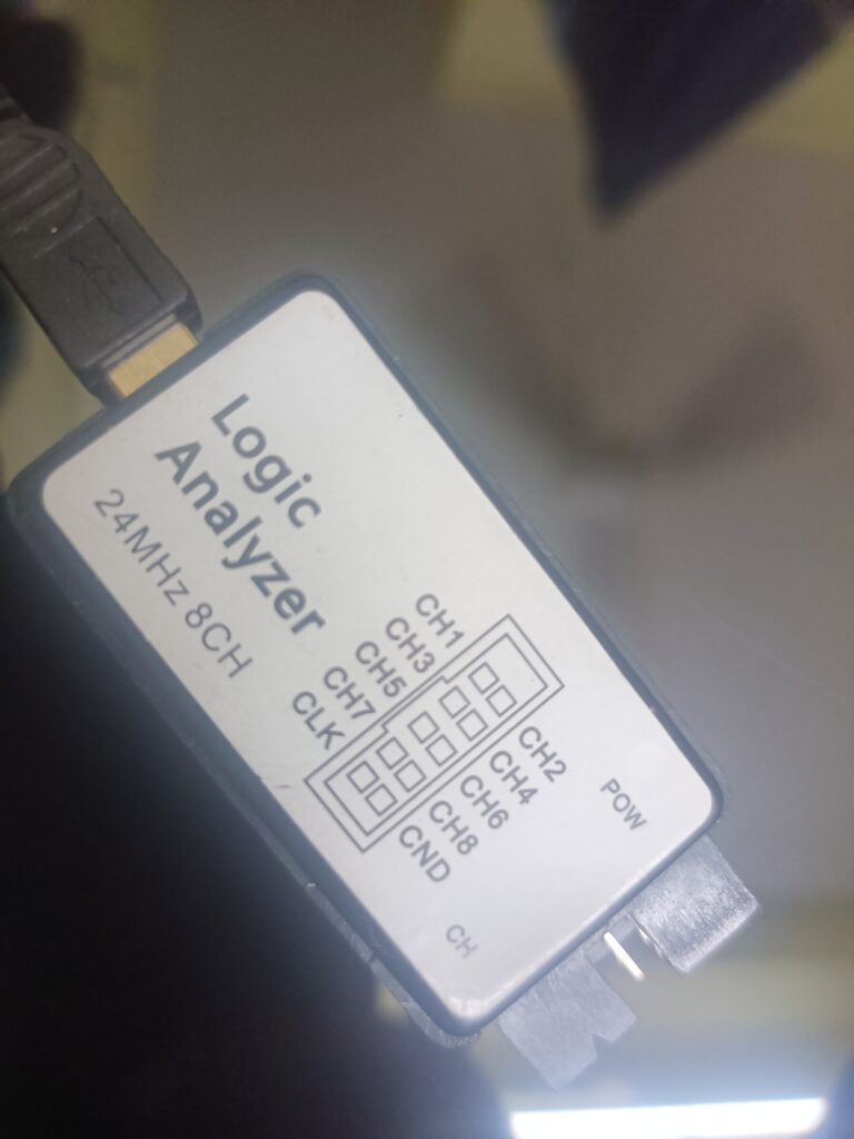
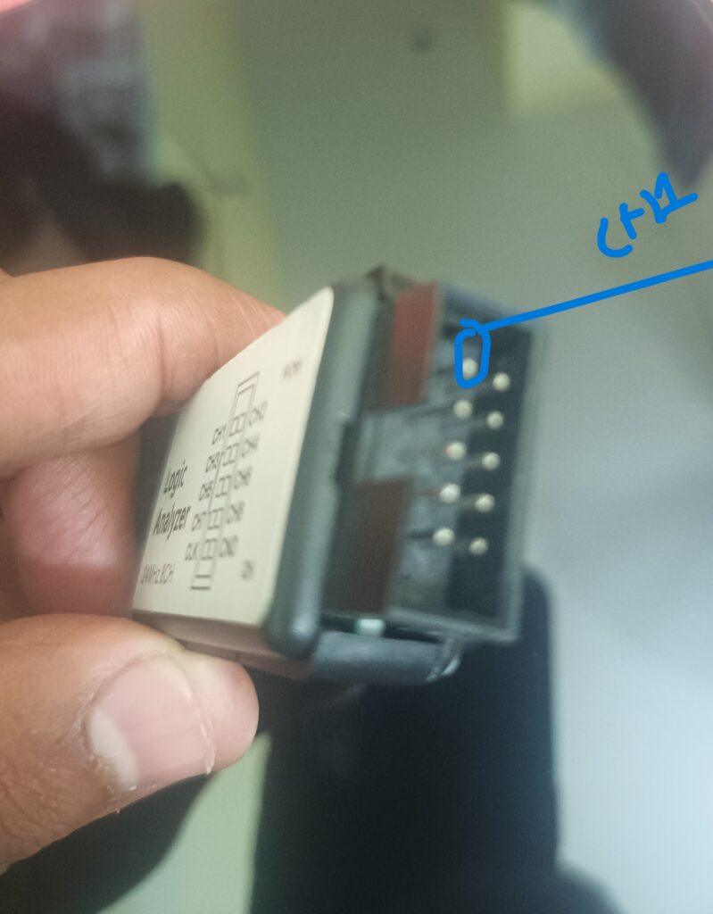
To see what’s happening on pin 13, I connected the Saleae Logic Analyzer probe to Arduino pin 13 and ground. This allows the Logic Analyzer to measure the voltage changes as the LED turns on and off.
What I Learned from the Logic Analyzer
When I opened the Saleae software and started capturing data, I saw a clean square wave pattern on channel 0 corresponding to pin 13. The signal was HIGH for about 1 second and LOW for about 0.5 seconds, exactly as my code intended.
This visual confirmation helped me understand:
- How digital signals appear as voltage changes (HIGH = ~5V, LOW = 0V).
- Timing between signal changes, like the 1-second ON and 0.5-second OFF.
- The importance of accurate timing in embedded programming.
Why Use a Logic Analyzer?
- Debugging: It helps find errors in signal timing or logic.
- Learning: Visualizing signals makes digital electronics easier to understand.
- Complex Projects: When dealing with communication protocols like I2C or SPI, it’s invaluable.
Final Tips for Beginners
- Always connect the ground of the Logic Analyzer to the Arduino ground.
- Start with simple code like blinking an LED before moving to complex signals.
- Use the Saleae software features like zoom and cursors to measure signal duration.
- Don’t be afraid to experiment and observe how changes in code affect the signal.
Using a Saleae Logic Analyzer with an Arduino Uno is a fantastic way to bring digital signals to life and deepen your understanding of embedded electronics. Happy learning
You can also Visit other tutorials of Embedded Prep
- Decode I²C with Saleae Logic Analyzer
- Top 30+ I2C Interview Questions
- Bit Manipulation Interview Questions
- Structure and Union in c
- Fault Handling in Arm Cortex Mx Processor
- Merge sort algorithm
Special thanks to @mr-raj for contributing to this article on EmbeddedPrep
Mr. Raj Kumar is a highly experienced Technical Content Engineer with 7 years of dedicated expertise in the intricate field of embedded systems. At Embedded Prep, Raj is at the forefront of creating and curating high-quality technical content designed to educate and empower aspiring and seasoned professionals in the embedded domain.
Throughout his career, Raj has honed a unique skill set that bridges the gap between deep technical understanding and effective communication. His work encompasses a wide range of educational materials, including in-depth tutorials, practical guides, course modules, and insightful articles focused on embedded hardware and software solutions. He possesses a strong grasp of embedded architectures, microcontrollers, real-time operating systems (RTOS), firmware development, and various communication protocols relevant to the embedded industry.
Raj is adept at collaborating closely with subject matter experts, engineers, and instructional designers to ensure the accuracy, completeness, and pedagogical effectiveness of the content. His meticulous attention to detail and commitment to clarity are instrumental in transforming complex embedded concepts into easily digestible and engaging learning experiences. At Embedded Prep, he plays a crucial role in building a robust knowledge base that helps learners master the complexities of embedded technologies.