Introduction to GPIO
GPIO : In the world of electronics and embedded systems, GPIO is a term you will encounter very often.
GPIO stands for General Purpose Input/Output. It refers to programmable pins on a microcontroller, microprocessor, or SoC (System on Chip) that can be controlled through software to perform simple tasks like reading a sensor value or controlling an LED.
In this beginner-friendly tutorial, we will break down GPIOs in a very simple way, perfect for those just getting started!
What is GPIO?
GPIO pins are versatile electrical connections.
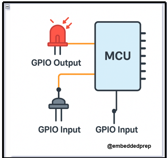
They can be configured either as input or output depending on what you want to do:
- Input Mode: The GPIO pin reads a signal, such as a button press.
- Output Mode: The GPIO pin sends a signal, such as turning on an LED or running a motor.
Think of GPIO pins as the communication wires between your software and hardware.
Why is GPIO Important?
GPIO pins allow microcontrollers and processors to interact with the physical world.
Without GPIO, you wouldn’t be able to connect buttons, sensors, LEDs, or many other hardware components to your board.
They are used for:
- Reading data from sensors (temperature, humidity, motion, etc.)
- Controlling outputs (LEDs, motors, relays)
- Communicating with other devices (using protocols like SPI, I2C, UART)
How Does GPIO Work?
Basic Steps:
- Configure the Pin Direction
- Set the GPIO pin as either INPUT or OUTPUT.
- Write or Read Data
- If OUTPUT, send a HIGH (1) or LOW (0) voltage.
- If INPUT, read the voltage level to determine the signal (pressed, not pressed, etc.).
- Use Pull-up or Pull-down Resistors
- These resistors ensure the GPIO pin has a default voltage when nothing is connected.
Real-World Example: Blinking an LED with GPIO
Let’s understand GPIO with a simple example: Blinking an LED using a microcontroller like Arduino.
Components Needed:
- 1 x LED
- 1 x 220-ohm resistor
- 1 x Arduino board
- Breadboard and wires
Circuit Connection:
- Connect the longer leg of the LED (anode) to GPIO pin 13 through the resistor.
- Connect the shorter leg (cathode) to GND (Ground).
Arduino Code Example:
void setup() {
  pinMode(13, OUTPUT); // Set GPIO 13 as OUTPUT
}

void loop() {
  digitalWrite(13, HIGH); // Turn LED ON
  delay(1000);            // Wait for 1 second
  digitalWrite(13, LOW);  // Turn LED OFF
  delay(1000);            // Wait for 1 second
}
Explanation:
pinMode(13, OUTPUT)configures pin 13 as an output pin.digitalWrite(13, HIGH)sends a HIGH voltage to turn on the LED.digitalWrite(13, LOW)sends a LOW voltage to turn off the LED.delay(1000)waits for 1000 milliseconds (1 second) between ON and OFF.
Important GPIO Terms You Should Know
| Term | Meaning |
|---|---|
| HIGH | Logical 1 or 3.3V/5V (depending on board) |
| LOW | Logical 0 or 0V (Ground) |
| Pull-up resistor | Keeps input HIGH when switch is open |
| Pull-down resistor | Keeps input LOW when switch is open |
Best Practices When Working with GPIOs
- Always check the maximum voltage and current that your GPIO pin can handle.
- Use resistors to protect your GPIO pins from damage.
- Debounce inputs like buttons to avoid false triggering.
- When using output GPIOs to drive high-power devices (like motors), use transistors or relays.
GPIO Practical Example on ARM Cortex-M4 Processor (STM32)
Introduction
When working with ARM Cortex-M4 microcontrollers (like STM32F4 series), controlling GPIO pins is one of the first and most important tasks you’ll learn.
In this tutorial, we’ll show you how to configure a GPIO pin to blink an LED using STM32 microcontroller, and understand what’s happening step-by-step!
Let’s dive right in. 🚀
Prerequisites
Before we start, you should have:
- An STM32F4 (or similar Cortex-M4 board)
- STM32CubeIDE installed (free official IDE from STMicroelectronics)
- A basic setup (board, USB cable)
GPIO Basics on ARM Cortex-M4
On STM32, each pin is part of a GPIO port like GPIOA, GPIOB, GPIOC, etc.
Each GPIO pin needs:
- Clock Enable (for the GPIO port)
- Pin Mode Configuration (Input, Output, Alternate Function, Analog)
- Output Type (Push-Pull or Open-Drain)
- Pull-up/Pull-down (None, Pull-up, Pull-down)
- Speed (Low, Medium, High)
Step-by-Step: Blinking an LED on STM32 (Cortex-M4)
1. Hardware Setup
- Use the on-board LED (usually connected to Pin PA5 on Nucleo-F401RE, or check your board’s datasheet).
- If no onboard LED, connect an LED through a resistor to PA5 and GND.
2. Software Setup (STM32CubeIDE)
Create a New STM32 Project:
- Open STM32CubeIDE.
- Click File > New > STM32 Project.
- Select your MCU (example: STM32F401RE).
- Name your project (
GPIO_Blink).
Configure GPIO:
In the Pinout & Configuration view:
- Click on pin PA5 (or your chosen pin).
- Set it as GPIO_Output.
CubeIDE automatically configures the GPIO clock and settings!
3. Write the Code
Go to Src/main.c and edit the code:
#include "main.h"

int main(void)
{
  HAL_Init(); // Initialize Hardware Abstraction Layer

  __HAL_RCC_GPIOA_CLK_ENABLE(); // Enable clock for GPIOA

  GPIO_InitTypeDef GPIO_InitStruct = {0};

  // Configure PA5 as Output
  GPIO_InitStruct.Pin = GPIO_PIN_5;
  GPIO_InitStruct.Mode = GPIO_MODE_OUTPUT_PP; // Push-Pull Output
  GPIO_InitStruct.Pull = GPIO_NOPULL;
  GPIO_InitStruct.Speed = GPIO_SPEED_FREQ_LOW;
  HAL_GPIO_Init(GPIOA, &GPIO_InitStruct);

  while (1)
  {
    HAL_GPIO_TogglePin(GPIOA, GPIO_PIN_5); // Toggle LED
    HAL_Delay(500);                        // Delay 500 ms
  }
}
4. Build and Flash the Code
- Click the hammer icon (build project).
- Connect your board.
- Click the green play button (flash and run).
You should see the LED blinking every 500ms!
What’s Happening Behind the Scenes?
| Step | Description |
|---|---|
HAL_Init() | Initializes the HAL Library. |
__HAL_RCC_GPIOA_CLK_ENABLE() | Enables the clock for GPIOA peripheral. |
HAL_GPIO_Init() | Sets pin PA5 as output, no pull-up/down, low speed. |
HAL_GPIO_TogglePin() | Changes pin state (HIGH to LOW or LOW to HIGH). |
HAL_Delay() | Creates a software delay to control blink rate. |
Tips for GPIO on ARM Cortex-M4
- Always enable the clock for the GPIO port before configuring.
- Use HAL library for easier and safer coding (good for beginners).
- For high-speed GPIO, set GPIO Speed to
GPIO_SPEED_FREQ_HIGH. - Read the Reference Manual of your microcontroller to understand more detailed control.
Imagine it like this:
A GPIO pin is like a small door.
- When you listen at the door → It’s an input.
- When you shout through the door → It’s an output.
And you (the programmer) decide whether to listen or shout through the door!
How GPIO Works Internally (Step-by-Step)
1. GPIO Pin is Connected to Internal Hardware
Every GPIO pin is connected to a small electrical circuit inside the microcontroller.
This circuit can behave differently based on how you configure it.
At its heart, the pin connects to:
- Logic gates
- Pull-up/pull-down resistors
- Drive transistors
- MUX (Multiplexer for selecting function)
2. Configure the Pin as Input or Output
When you write software for your MCU, the first thing you do is configure the pin:
- Input mode: The pin will listen to outside voltage (HIGH or LOW).
- Output mode: The pin will send a voltage signal (HIGH or LOW) outside.
💬 In most microcontrollers, you configure this using special control registers (small memory locations inside the chip).
Example (STM32):
GPIOA->MODER |= (1 << (2 * 5)); // Set PA5 as output
This means you’re telling the chip: “Hey, PA5, work as output!“
3. How Input Mode Works
When the pin is in input mode:
- It waits and senses if the voltage on the pin is High (1) or Low (0).
- High means ~3.3V (depends on MCU).
- Low means ~0V.
If the signal is unstable, internal pull-up or pull-down resistors can be activated to stabilize it.
4. How Output Mode Works
When the pin is in output mode:
- The software can write 1 or 0 to the pin.
- Writing 1: The internal circuit connects the pin to 3.3V (HIGH).
- Writing 0: The internal circuit connects the pin to GND (LOW).
Example (STM32 HAL):
HAL_GPIO_WritePin(GPIOA, GPIO_PIN_5, GPIO_PIN_SET); // Set PA5 High
HAL_GPIO_WritePin(GPIOA, GPIO_PIN_5, GPIO_PIN_RESET); // Set PA5 Low
Thus, the pin can turn ON an LED, activate a motor, or send data to another device.
5. Special Features Inside GPIO
GPIOs are not just dumb wires. They have smart features:
| Feature | Meaning |
|---|---|
| Pull-up / Pull-down | Stabilize input when nothing connected |
| Open-Drain | Pin can pull LOW but not drive HIGH (external pull-up needed) |
| Speed Control | Control how fast pin changes (important for EMI) |
| Alternate Functions | GPIO can become UART, SPI, I2C pins when needed |
| Interrupt Capability | GPIO can detect changes and alert CPU instantly |
GPIO Life Cycle in Software
Typical steps in a C program:
- Enable the GPIO port clock (power the module).
- Configure the pin mode (input/output/alternate).
- Set pull-up or pull-down resistors if needed.
- Set speed (for output pins).
- Read or Write data.
This process never changes — whether you’re working on STM32, NXP, or TI boards.
Real-Life Practical Example (ARM Cortex-M4)
Example Task: Blink an LED using PA5 pin
Software Steps:
// 1. Enable GPIOA Clock
RCC->AHB1ENR |= (1 << 0); // Enable clock to GPIOA

// 2. Set PA5 as output
GPIOA->MODER &= ~(3 << (2 * 5)); // Clear Mode Bits
GPIOA->MODER |= (1 << (2 * 5));  // Set Output Mode

// 3. Toggle PA5 forever
while(1) {
    GPIOA->ODR ^= (1 << 5); // Toggle PA5
    for (volatile int i = 0; i < 100000; i++); // Small delay
}
Result:
The LED connected to PA5 will blink continuously.
Important Concepts to Remember
| Concept | Summary |
|---|---|
| Input Mode | Reads voltage from external world |
| Output Mode | Sends voltage to external world |
| Floating | Input pin without pull-up/down can behave randomly |
| Pull-up/Pull-down | Avoid undefined signals on inputs |
| Open-Drain Output | Safer for multi-device communication |
| Alternate Functions | Turn GPIO into UART, SPI, I2C, PWM, etc. |
| Debounce | Clean noisy signals from mechanical buttons |
GPIO Interview Questions for Embedded Systems
Basic Level
- What is GPIO? Explain its role in microcontrollers.
- What is the difference between GPIO input and GPIO output?
- What are pull-up and pull-down resistors? Why are they important in GPIO input mode?
- How do you configure a GPIO pin as an output in ARM Cortex-M4?
- What happens if you leave a GPIO input pin floating?
- What is the difference between push-pull and open-drain output configurations?
- Explain the concept of debouncing. Why is it needed for GPIO inputs?
Intermediate Level
- Describe the steps needed to configure a GPIO pin manually (without using a HAL library).
- What registers are involved in GPIO configuration on ARM Cortex-M4 (STM32)?
- How would you implement GPIO interrupts for a button press?
- Explain the importance of enabling the peripheral clock before accessing GPIO registers.
- What is alternate function mode in GPIOs? Give examples where it’s used.
- How would you drive an LED matrix using GPIOs?
- What are the power considerations when using GPIOs, especially in battery-operated devices?
- What is GPIO drive strength? Why does it matter in certain designs?
Advanced Level
- Explain how you would design a low-power GPIO input system.
- Describe a scenario where open-drain GPIO configuration is preferred over push-pull.
- How do you configure GPIO wake-up from sleep or standby mode in ARM Cortex-M4?
- How would you handle a situation where multiple peripherals share the same GPIO pins?
- What are the risks of GPIO glitches during boot or reset, and how can you minimize them?
- How do GPIO multiplexers work internally in microcontrollers?
- How would you optimize GPIO control for high-speed applications (e.g., toggling pins in MHz range)?
Practical / Coding Level
- Write a C code snippet to configure PA0 as input with pull-up resistor on STM32.
- Write a code to toggle a GPIO pin at a 1-second interval without using HAL libraries.
- How would you structure GPIO initialization code for easy scalability in large embedded projects?
Bonus Questions (for Deeper Insight)
- Have you ever used GPIO pins for bit-banging protocols like I2C or SPI? Explain how.
- What are the key differences in GPIO handling between STM32, NXP, and TI microcontrollers?
- How would you simulate a GPIO toggle using a timer interrupt?
GPIO FAQs (Frequently Asked Questions)
1. What is GPIO in a microcontroller?
Answer:
GPIO stands for General Purpose Input/Output. It allows microcontrollers to read external signals (input) or control external devices (output) like LEDs, buttons, sensors, motors, etc.
2. What is the difference between GPIO input and GPIO output?
Answer:
- GPIO Input: Reads external signals (like button presses or sensor outputs).
- GPIO Output: Sends signals to control external devices (like LEDs, buzzers, relays).
3. What are pull-up and pull-down resistors in GPIO?
Answer:
Pull-up and pull-down resistors prevent GPIO input pins from floating (i.e., being in an undefined state) by tying them to a known voltage:
- Pull-up: Connects the pin weakly to Vcc (logic high).
- Pull-down: Connects the pin weakly to GND (logic low).
4. Why do we enable the GPIO clock before using GPIO?
Answer:
Microcontrollers use clock gating to save power.
Without enabling the GPIO clock, the GPIO registers are inaccessible, and the pin cannot function properly.
5. What is the purpose of GPIO alternate function mode?
Answer:
Alternate function mode allows a GPIO pin to be repurposed for other hardware functions like:
- UART (Serial communication)
- SPI (Serial Peripheral Interface)
- I2C (Inter-Integrated Circuit)
- PWM (Pulse Width Modulation)
6. What is push-pull vs open-drain GPIO configuration?
Answer:
- Push-Pull: The pin can actively drive both high and low voltage levels.
- Open-Drain: The pin can only pull the line low or stay floating (external pull-up required).
Tip: Open-drain is commonly used in I2C and shared-bus designs.
7. What happens if a GPIO input pin is left floating?
Answer:
If left floating, the GPIO input can randomly read HIGH or LOW, causing unpredictable behavior due to electrical noise.
Solution: Always configure input pins with a pull-up or pull-down resistor.
8. How to configure a GPIO pin in STM32?
Answer:
Steps to configure:
- Enable the GPIO port clock.
- Set the pin mode (Input/Output/Alternate/Analog).
- Configure output type (Push-Pull/Open-Drain).
- Set pull-up/pull-down resistors.
- Define pin speed (Low/Medium/High).
- Write or read data to/from the pin.
9. How to toggle a GPIO pin in C?
Answer:
Example (STM32 HAL):
HAL_GPIO_TogglePin(GPIOA, GPIO_PIN_5);
This function toggles the state of the specified GPIO pin.
10. What is debouncing and why is it needed for GPIO inputs?
Answer:
Debouncing is the process of removing noisy, fast-changing signals generated by mechanical switches when pressed or released.
Without debouncing, a single button press might be registered as multiple presses.
Solutions:
- Software debounce (adding small delay)
- Hardware debounce (using capacitors or circuits)
11. Can GPIOs be used for interrupts?
Answer:
Yes!
GPIOs can be configured to generate interrupts on events like:
- Rising edge (LOW to HIGH)
- Falling edge (HIGH to LOW)
- Both edges
This is useful for buttons, sensors, and real-time events.
12. How fast can a GPIO toggle?
Answer:
It depends on:
- Microcontroller clock speed
- GPIO speed settings (Low/Medium/High/Fast)
- Code execution time
With direct register access (bare-metal), GPIOs can toggle at several megahertz (MHz) frequencies.
13. How can I reduce GPIO power consumption?
Answer:
To minimize GPIO power use:
- Set unused GPIOs to analog mode.
- Avoid floating inputs.
- Use pull-downs or pull-ups appropriately.
- Reduce output toggle frequency if not needed.
14. How to protect GPIO pins from damage?
Answer:
Protection methods:
- Use series resistors.
- Use TVS (Transient Voltage Suppression) diodes.
- Never exceed the maximum voltage/current ratings.
- Add current-limiting resistors for outputs like LEDs.
15. What is GPIO multiplexing?
Answer:
GPIO multiplexing allows one physical pin to perform multiple functions based on configuration (e.g., GPIO, UART TX, SPI MISO, etc.).
The correct function is selected by setting MUX bits in the configuration registers.
Special thanks to @mr-raj for contributing to this article on Embedded Prep
Mr. Raj Kumar is a highly experienced Technical Content Engineer with 7 years of dedicated expertise in the intricate field of embedded systems. At Embedded Prep, Raj is at the forefront of creating and curating high-quality technical content designed to educate and empower aspiring and seasoned professionals in the embedded domain.
Throughout his career, Raj has honed a unique skill set that bridges the gap between deep technical understanding and effective communication. His work encompasses a wide range of educational materials, including in-depth tutorials, practical guides, course modules, and insightful articles focused on embedded hardware and software solutions. He possesses a strong grasp of embedded architectures, microcontrollers, real-time operating systems (RTOS), firmware development, and various communication protocols relevant to the embedded industry.
Raj is adept at collaborating closely with subject matter experts, engineers, and instructional designers to ensure the accuracy, completeness, and pedagogical effectiveness of the content. His meticulous attention to detail and commitment to clarity are instrumental in transforming complex embedded concepts into easily digestible and engaging learning experiences. At Embedded Prep, he plays a crucial role in building a robust knowledge base that helps learners master the complexities of embedded technologies.