ARM Cortex-M4 Interrupt Handling : In embedded systems, handling asynchronous events like incoming data from external devices is crucial for responsive and efficient software design. One powerful mechanism used for this purpose is interrupts. Instead of continuously polling a peripheral, the microcontroller (MCU) can be configured to automatically respond to specific events, such as data arrival in a UART (USART) buffer.
This article walks you through the step-by-step interrupt handling process using a USART peripheral as an example. You’ll learn how the data flow, NVIC (Nested Vectored Interrupt Controller), and CPU work together to handle interrupts — from the moment a data packet arrives, to executing the interrupt service routine (ISR) that processes the data.
Whether you’re working with ARM Cortex-M microcontrollers or just beginning your journey into embedded development, this guide will help you build a clear mental model of how peripheral interrupts operate under the hood.
ARM Cortex-M4 Interrupt Handling
Core Peripheral Register Regions (ARM Cortex-M)
| Address Range | Core Peripheral | Description |
|---|---|---|
0xE000E008 – 0xE000E00F | System Control Block (SCB) | Contains control and status registers like ACTLR, used for system configuration. |
0xE000E010 – 0xE000E01F | System Timer (SysTick) | A 24-bit timer that provides a simple way to generate delays or time slices. |
0xE000E100 – 0xE000E4EF | Nested Vectored Interrupt Controller | Manages external and internal interrupt handling with programmable priorities. |
0xE000ED00 – 0xE000ED3F | System Control Block (Extended) | Additional system control and status registers including CPUID, ICSR, etc. |
0xE000ED90 – 0xE000ED93 | MPU Type Register | Used to detect if MPU is implemented. If value reads 0, then MPU is not present. |
0xE000ED90 – 0xE000EDB8 | Memory Protection Unit (MPU) | Defines memory regions and their attributes to prevent invalid memory access. |
0xE000EF00 – 0xE000EF03 | NVIC (Software Trigger Interrupt Reg) | Used to trigger interrupts through software. |
0xE000EF30 – 0xE000EF44 | Floating Point Unit (FPU) | Registers and controls for the floating-point coprocessor (if supported). |
NVIC (Nested Vectored Interrupt Controller) registers in ARM Cortex-M microcontrollers.
Explanation of Each Row
| Field | Meaning |
|---|---|
| Address | Memory range for the register(s) |
| Name | Name of the register |
| Type | RW = Read/Write, WO = Write-Only |
| Required privilege | Access level needed (Privileged or Configurable) |
| Reset value | Default value after reset (usually all 0s = disabled) |
| Description | Purpose and detailed usage of the register |
Registers and Their Roles
| Register Name | Function |
|---|---|
| NVIC_ISER0 – NVIC_ISER7 (Interrupt Set-Enable Registers) | Enables interrupts. Writing a 1 to a bit enables the corresponding interrupt. |
| NVIC_ICER0 – NVIC_ICER7 (Interrupt Clear-Enable Registers) | Disables interrupts. Writing a 1 clears (disables) the corresponding interrupt. |
| NVIC_ISPR0 – NVIC_ISPR7 (Interrupt Set-Pending Registers) | Sets an interrupt as pending (as if it was triggered). Used for software-triggered interrupts. |
| NVIC_ICPR0 – NVIC_ICPR7 (Interrupt Clear-Pending Registers) | Clears the pending status of interrupts. |
| NVIC_IABR0 – NVIC_IABR7 (Interrupt Active Bit Registers) | Shows which interrupts are currently active (being serviced). |
| NVIC_IPR0 – NVIC_IPR59 (Interrupt Priority Registers) | Sets priority for each interrupt (lower number = higher priority). |
| STIR (Software Trigger Interrupt Register) | Lets software trigger an interrupt manually. Write the interrupt number to trigger it. |
Privilege Levels
- Privileged: Requires the code to run in privileged mode (usually kernel/system code).
- Configurable: Can be accessible depending on system setup and access permissions.
Example Use Case (Enable Interrupt #5):
NVIC_ISER[0] = (1 << 5); // Enable interrupt 5
Example Use Case (Set Interrupt 5 as Pending):
NVIC_ISPR[0] = (1 << 5); // Set pending flag
Example Use Case (Set Priority of Interrupt 5):
NVIC_IPR[1] = (3 << 6); // Priority level (varies by implementation)Steps to Program an MCU Peripheral Interrupt
1. Identify the IRQ Number
- Look up the IRQ number of the peripheral in the MCU’s vector table.
- Example: For USART3, the IRQ number might be
39(vendor-specific).
📌 This IRQ number maps to an entry in the NVIC interrupt table, and it’s essential to configure it correctly.
2. Enable the IRQ in the Processor
- Use the NVIC_ISERx (Interrupt Set-Enable Register) to enable the IRQ number.
- Optionally, use the NVIC_IPRx (Interrupt Priority Register) to set its priority.
NVIC_ISER1 |= (1 << (39 % 32));       // Enable IRQ39
NVIC_IPR9 = (3 << 6);                 // Optional: Set priority for IRQ39 (lower value = higher priority)
📘 The processor won’t recognize interrupts unless they’re enabled in NVIC.
3. Configure the Peripheral
- Set up the peripheral (e.g., USART3) to generate an interrupt.
- This is done through its own control/status registers (e.g., USART_CR1 for enabling RXNEIE — RX Not Empty Interrupt Enable).
USART3->CR1 |= USART_CR1_RXNEIE; // Enable RX interrupt for USART3
4. Pending Register Behavior
- When USART3 receives data, it automatically issues an interrupt on IRQ 39.
- This interrupt gets logged (pended) in the NVIC_ISPRx (Interrupt Set-Pending Register).
5. NVIC Checks Priority Before Serving
- NVIC checks:
- Is the IRQ enabled?
- Is the priority of this interrupt higher than the one currently being served?
- If yes, it triggers the Interrupt Service Routine (ISR).
- If no, the interrupt stays pending until it becomes the highest-priority pending interrupt.
6. Interrupt Behavior When IRQ is Disabled
- Even if you haven’t enabled the IRQ in NVIC, the peripheral can still issue the interrupt.
- It gets stored in the pending state.
- When you later enable the IRQ:
- If its priority is high enough, the ISR will execute immediately.
Summary Flow:
Peripheral event (e.g., USART3 receives data) -->
Peripheral asserts IRQ (e.g., IRQ39) -->
NVIC pends the IRQ (ISPRx) -->
If enabled and high-priority, NVIC dispatches ISR -->
Your code executes the ISR (Interrupt Service Routine)
Interrupt Handling Flow for USART RX Data
Step 1: Data Arrival
- What happens: A data packet comes in from the external world and is received by the USART RX buffer.
- Where: In the USART peripheral (e.g., USART3).
- Why: Because a device (e.g., another MCU, terminal, etc.) is sending data over the serial line.
Step 2: Interrupt Request Issued
- What happens: The USART peripheral detects new data in its RX buffer and triggers an interrupt.
- How: It asserts its IRQ line (in this case, IRQ number 39) to notify the processor.
📌 This step depends on the fact that RX interrupt is enabled in the peripheral control register (USART_CR1).
Step 3: NVIC Registers the Interrupt
- What happens:
- The IRQ 39 becomes pending in the NVIC’s pending register (ISPRx).
- If the IRQ is enabled and has sufficient priority, NVIC prepares to handle it.
- Visual: This is shown as the yellow box inside NVIC with a 39 marked line going into the pending register.
Step 4: CPU Handles Interrupt
- What happens:
- CPU fetches the ISR address from the vector table based on IRQ number 39.
- CPU jumps to the ISR (Interrupt Service Routine).
- Note: The Program Counter (PC) is updated with the ISR address.
Step 5: ISR Executes
- What happens: The ISR (Interrupt Service Routine) runs.
- What it does: It typically copies the received data from the USART RX buffer into SRAM (main memory) or processes it accordingly.
Summary Flowchart:
External Data → USART RX Buffer
       ↓
USART Issues IRQ (e.g., 39)
       ↓
NVIC Marks IRQ as Pending (if enabled)
       ↓
CPU Fetches ISR from Vector Table
       ↓
ISR Executes (e.g., copy data to SRAM)
Developer Notes:
- This entire flow is hardware-assisted and efficient, allowing the CPU to react quickly to events without polling.
- You must:
- Enable RX interrupt in USART.
- Enable IRQ in NVIC.
- Write the correct ISR function in your firmware.
Interrupt Priority, Preempt Priority & Sub Priority
In embedded systems, interrupts help your program quickly respond to important events (like a button press or sensor signal) even while it’s doing something else. But what happens when two or more interrupts occur at the same time?
That’s where priority comes in!
What is Interrupt Priority?
Every interrupt is assigned a priority to help the microcontroller decide which interrupt to serve first.
👉 Higher priority interrupts get serviced before lower priority ones.
For example:
- If Timer1 (priority 2) and USART1 (priority 1) occur at the same time, USART1 will be handled first.
What is Preempt Priority?
Preempt Priority decides whether one interrupt can interrupt another that’s already running.
🔁 If a new interrupt with higher preempt priority comes while another is running, it will preempt (pause) the running one and start executing.
👉 Think of it like a teacher calling a more urgent student to speak even if another student is already speaking.
What is Sub Priority?
Sub Priority helps decide which interrupt runs first when two interrupts have the same preempt priority.
⚠️ Sub-priority does not cause preemption — it only helps resolve the order when two interrupts are pending with the same level.
Example Analogy:
| Interrupt | Preempt Priority | Sub Priority | Meaning |
|---|---|---|---|
| USART1 | 1 | 1 | Medium importance |
| Timer2 | 0 | 0 | Highest importance |
| EXTI0 (button) | 1 | 0 | Medium but slightly more urgent |
Example Code: STM32 Interrupt Priority
Let’s use STM32CubeIDE and configure priorities for 3 interrupts:
- EXTI0 (button)
- TIM2 (timer)
- USART1 (serial communication)
NVIC Priority Configuration
// main.c or user init function
HAL_NVIC_SetPriorityGrouping(NVIC_PRIORITYGROUP_2); // 2 bits for preemption, 2 for sub-priority

// Set TIM2 interrupt: Highest priority
HAL_NVIC_SetPriority(TIM2_IRQn, 0, 0); // Preempt: 0, Sub: 0
HAL_NVIC_EnableIRQ(TIM2_IRQn);

// Set EXTI0 interrupt: Mid priority
HAL_NVIC_SetPriority(EXTI0_IRQn, 1, 0); // Preempt: 1, Sub: 0
HAL_NVIC_EnableIRQ(EXTI0_IRQn);

// Set USART1 interrupt: Lowest priority
HAL_NVIC_SetPriority(USART1_IRQn, 1, 1); // Preempt: 1, Sub: 1
HAL_NVIC_EnableIRQ(USART1_IRQn);
ISR (Interrupt Service Routines)
void TIM2_IRQHandler(void)
{
    HAL_TIM_IRQHandler(&htim2);
    HAL_GPIO_TogglePin(GPIOC, GPIO_PIN_13); // Toggle LED
}

void EXTI0_IRQHandler(void)
{
    HAL_GPIO_EXTI_IRQHandler(GPIO_PIN_0);
    HAL_UART_Transmit(&huart1, (uint8_t*)"EXTI0 triggered\n", 16, HAL_MAX_DELAY);
}

void USART1_IRQHandler(void)
{
    HAL_UART_IRQHandler(&huart1);
    // Maybe echo back received data
}
Summary
| Term | Controls | Can Interrupt Others? | Purpose |
|---|---|---|---|
| Preempt Priority | Whether one ISR interrupts another | ✅ Yes | Preemption behavior |
| Sub Priority | Order if same preempt level | ❌ No | Resolves conflict silently |
Notes
HAL_NVIC_SetPriorityuses(preempt, sub)as inputs.- Lower number = Higher priority.
- Priority grouping sets how bits are divided between preempt and sub.
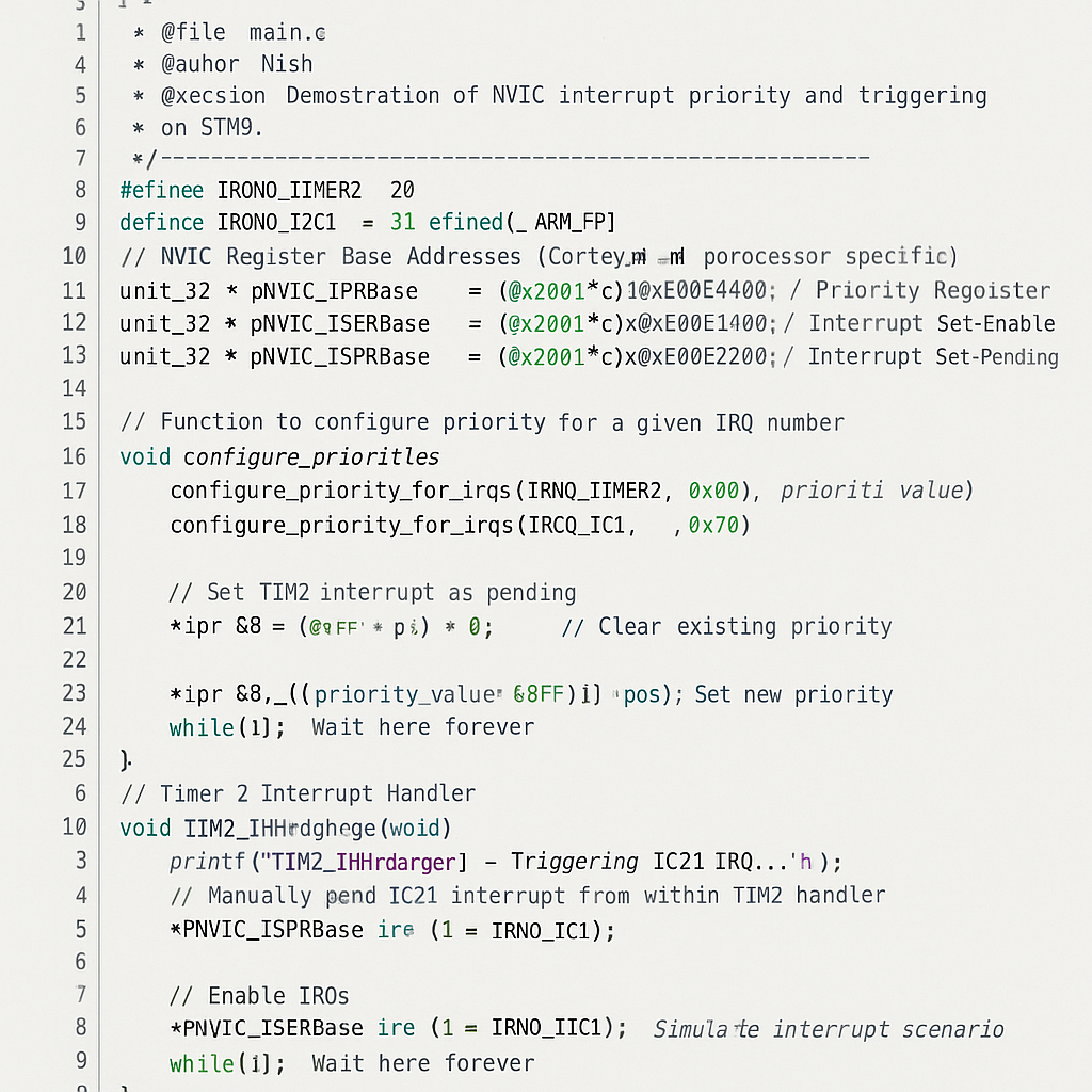
NVIC Interrupt Priority Configuration and Manual Triggering on STM32
#if !defined(__SOFT_FP__) && defined(__ARM_FP)
  #warning "FPU is not initialized, but the project is compiling for an FPU. Please initialize the FPU before use."
#endif#define IRQNO_TIMER2  28
#define IRQNO_I2C1    31

#include <stdint.h>
#include <stdio.h>

// NVIC Register Base Addresses (Cortex-M processor specific)
uint32_t *pNVIC_IPRBase  = (uint32_t*)0xE000E400; // Priority Register
uint32_t *pNVIC_ISERBase = (uint32_t*)0xE000E100; // Interrupt Set-Enable
uint32_t *pNVIC_ISPRBase = (uint32_t*)0xE000E200; // Interrupt Set-Pending

// Function to configure priority for a given IRQ number
void configure_priority_for_irqs(uint8_t irq_no, uint8_t priority_value)
{
    uint8_t iprx = irq_no / 4;
    uint32_t *ipr = pNVIC_IPRBase + iprx;

    uint8_t pos = (irq_no % 4) * 8;

    *ipr &= ~(0xFF << pos);                // Clear existing priority
    *ipr |=  ((priority_value & 0xFF) << pos);  // Set new priority
}

int main(void)
{
    // Configure priorities
    configure_priority_for_irqs(IRQNO_TIMER2, 0x80);
    configure_priority_for_irqs(IRQNO_I2C1,  0x70);

    // Set TIM2 interrupt as pending
    *pNVIC_ISPRBase |= (1 << IRQNO_TIMER2);

    // Enable IRQs
    *pNVIC_ISERBase |= (1 << IRQNO_I2C1);
    *pNVIC_ISERBase |= (1 << IRQNO_TIMER2);

    while(1); // Wait here forever
}

// Timer 2 Interrupt Handler
void TIM2_IRQHandler(void)
{
    printf("[TIM2_IRQHandler] - Triggering I2C1 IRQ...\n");

    // Manually pend I2C1 interrupt from within TIM2 handler
    *pNVIC_ISPRBase |= (1 << IRQNO_I2C1);

    while(1); // Stay here to simulate nested interrupt scenario
}

// I2C1 Event Interrupt Handler
void I2C1_EV_IRQHandler(void)
{
    printf("[I2C1_EV_IRQHandler] - Nested interrupt handled.\n");
}Mr. Raj Kumar is a highly experienced Technical Content Engineer with 7 years of dedicated expertise in the intricate field of embedded systems. At Embedded Prep, Raj is at the forefront of creating and curating high-quality technical content designed to educate and empower aspiring and seasoned professionals in the embedded domain.
Throughout his career, Raj has honed a unique skill set that bridges the gap between deep technical understanding and effective communication. His work encompasses a wide range of educational materials, including in-depth tutorials, practical guides, course modules, and insightful articles focused on embedded hardware and software solutions. He possesses a strong grasp of embedded architectures, microcontrollers, real-time operating systems (RTOS), firmware development, and various communication protocols relevant to the embedded industry.
Raj is adept at collaborating closely with subject matter experts, engineers, and instructional designers to ensure the accuracy, completeness, and pedagogical effectiveness of the content. His meticulous attention to detail and commitment to clarity are instrumental in transforming complex embedded concepts into easily digestible and engaging learning experiences. At Embedded Prep, he plays a crucial role in building a robust knowledge base that helps learners master the complexities of embedded technologies.