Welcome to the Master Beginner-Friendly Guide to the Embedded Boot Process (2025 Edition)! In this tutorial, you’ll gain a clear and practical understanding of how embedded systems start up — from the moment power is applied to the system until the operating system or application is fully running.
What You Will Learn:
- What is the Boot Process?
Understand what happens behind the scenes when an embedded device powers on. - Stages of the Boot Process:
- Power-On Reset (POR)
- Boot ROM / Initial Bootloader
- Secondary Bootloader (SPL / U-Boot)
- Kernel Loading
- Root Filesystem Mounting
- User Application Launch
- Key Components Involved:
Learn about bootloaders, memory maps, non-volatile storage (NAND, NOR, eMMC), and how firmware interacts with hardware. - Bare-metal vs. OS-based Booting:
Discover the difference in boot flow when using no OS, RTOS, or full-fledged OS like Linux or QNX. - Practical Example:
Walk through a real-world boot sequence on popular boards like STM32, BeagleBone Black, or Raspberry Pi. - Debugging Boot Issues:
Learn how to use serial consoles, boot logs, and debugging tools to trace boot-time failures. - Tips for Faster and Reliable Booting
Optimize your embedded system’s startup time and stability.
Have you ever wondered what happens when you turn on your computer or a device like a mobile phone or embedded board (e.g., Raspberry Pi, Arduino, etc.)?
Let’s break it down step by step, using simple words!
1. Power ON
When you press the power button:
- Electricity flows to the motherboard and components.
- This is just like waking up your device from sleep.
2. CPU Starts (but knows nothing!)
The CPU (brain of the system) starts running, but it has no idea what to do.
- So, it looks for instructions in a special memory called ROM (Read-Only Memory).
3. BIOS / Bootloader (First Instructions)
The CPU finds a tiny program in ROM, like a mini-guidebook. This is:
- BIOS (for PCs) or
- Bootloader (in embedded systems or phones)
This program:
- Checks if important parts like RAM, keyboard, screen, etc., are working.
- Then it looks for the main software (Operating System) to run.
4. Loading the Operating System (OS)
Once the check is done:
- It loads the OS (like Windows, Linux, Android, or RTOS) from storage (HDD/SSD/Flash) to RAM.
- RAM is like a fast-access workspace where the OS can run quickly.
5. OS Takes Over
Now the OS is running, and:
- It manages the hardware.
- It starts services and programs.
- It shows you the login screen or desktop.
Congratulations! 🎉 Your device is now ready to use!
Quick Summary (Like a Flowchart):
1. Power ON 🔌
2. CPU starts 🧠
3. Bootloader/BIOS runs 📦
4. OS is loaded 💿
5. OS takes control and system is ready 🖥️
Real Life Example (Simple Analogy):
Think of your device like a car:
- Battery ON → Supplies power
- Ignition Key Turned → CPU wakes up
- Dashboard Checks → Bootloader checks parts
- Engine Starts → OS is loaded
- You Can Drive → System ready for use
U-Boot Basics
What is U-Boot?
U-Boot (short for Universal Boot Loader) is an open-source bootloader used in embedded systems. It helps your device start up, initialize hardware, and load the operating system (like Linux, Android, or RTOS).
Why Do We Need U-Boot?
When you power on an embedded board (like a BeagleBone, STM32, or Raspberry Pi):
- The CPU runs from ROM and looks for a bootloader.
- U-Boot is loaded into RAM.
- U-Boot initializes hardware (memory, CPU, storage, etc.).
- U-Boot loads and boots the kernel (main OS).
U-Boot Components
U-Boot works in two stages:
1. First Stage Bootloader (SPL – Secondary Program Loader)
- Very small size, loaded from ROM or flash.
- Initializes basic things like DRAM (RAM).
- Loads the full U-Boot image from storage into RAM.
2. Second Stage Bootloader (Full U-Boot)
- Runs in RAM.
- Has full features: CLI, device drivers, environment variables, loading kernel, etc.
U-Boot in Action – Boot Flow
Let’s say you power on your embedded board:
Power ON
   ↓
ROM Code (fixed in CPU)
   ↓
SPL (from SD card, flash)
   ↓
U-Boot (full version loaded into RAM)
   ↓
Kernel (Linux, RTOS, etc.)
   ↓
Root Filesystem
   ↓
Your Application
Common U-Boot Commands
You interact with U-Boot via a command-line interface (serial terminal like PuTTY, Minicom, TeraTerm).
Here are some commonly used U-Boot commands:
| Command | Description |
|---|---|
help | List all commands |
printenv | Show environment variables |
setenv var value | Set environment variable |
saveenv | Save variables to flash |
boot | Boot the OS |
load | Load file into memory |
mmc, fatload, ext4load | Load files from SD card (FAT or EXT4) |
bootm | Boot a Linux kernel image (uImage) |
bootz | Boot a zImage |
booti | Boot an Image format (used for ARM64) |
run | Run a command script or bootcmd |
U-Boot Environment Variables
These are key-value pairs that control how the board boots.
bootcmd=run mmcboot
bootargs=console=ttyO0,115200 root=/dev/mmcblk0p2 rw
bootdelay=3
bootcmd– What command to run to boot the OSbootargs– Kernel arguments (console, root filesystem, etc.)bootdelay– Wait time (in seconds) before runningbootcmd
Booting from Different Sources
U-Boot can boot from:
- SD Card (
mmc dev 0,fatload mmc 0) - NAND / NOR Flash
- USB
- Ethernet (TFTP Boot)
Example: Boot Kernel from SD Card
mmc dev 0
fatload mmc 0:1 0x82000000 zImage
fatload mmc 0:1 0x88000000 am335x-boneblack.dtb
setenv bootargs console=ttyO0,115200 root=/dev/mmcblk0p2 rw
bootz 0x82000000 - 0x88000000
Explanation:
- Load kernel to memory
0x82000000 - Load Device Tree Blob (DTB)
- Set bootargs
- Boot with
bootz
U-Boot Compilation (Advanced but useful to know)
You can compile U-Boot from source:
Step 1: Get the Source
git clone https://source.denx.de/u-boot/u-boot.git
cd u-boot
Step 2: Select Board
make <board_defconfig> # e.g., make am335x_evm_defconfig
Step 3: Build U-Boot
make CROSS_COMPILE=arm-linux-gnueabihf- # or your toolchain prefix
Output Files
u-boot.img– U-Boot imageMLO– SPL (for some boards like BeagleBone)
Flashing U-Boot to Board
- SD Card: Place
MLOandu-boot.imgin boot partition. - Flash Memory: Use tools like
dd,flashcp, or manufacturer utilities.
Tips for Beginners
- Always backup your current U-Boot before changing it.
- Use serial console to access U-Boot.
- Keep a bootable SD card as recovery in case of a bad flash.
- Learn U-Boot environment—it’s key to customization.
Customizing U-Boot for Embedded Systems
Customizing U-Boot means modifying its behavior to suit your specific board, hardware, or use case — like setting boot arguments, adding splash screens, or enabling new peripherals.
Let’s walk through it step by step 👇
1. Prerequisites
Before customizing, make sure you have:
✅ A Linux PC or VM
✅ A toolchain (like arm-linux-gnueabihf-gcc)
✅ U-Boot source code
✅ Board information (CPU, RAM, Flash type)
✅ Serial communication tool (like Minicom or PuTTY)
2. Get the U-Boot Source Code
git clone https://source.denx.de/u-boot/u-boot.git
cd u-boot
3. Choose the Right Board Configuration
U-Boot uses defconfig files for board settings.
To find yours:
ls configs/
Pick your board (example: BeagleBone Black)
make am335x_evm_defconfig
For custom boards, copy a similar defconfig and modify it.
4. Build U-Boot
export CROSS_COMPILE=arm-linux-gnueabihf-
make -j$(nproc)
You’ll get output files like:
MLO– SPL for initial bootu-boot.img– Main U-Bootu-boot.bin,u-boot.lds, etc.
5. Customizing U-Boot Features
A. Change Default Boot Command
Edit include/configs/<your_board>.h:
#define CONFIG_BOOTCOMMAND "run mmcboot"
You can replace it with your custom script:
#define CONFIG_BOOTCOMMAND "fatload mmc 0:1 0x82000000 zImage; bootz 0x82000000"
B. Change Environment Variables
Default environment is set in:
include/env_default.h
You can hardcode:
ENV_DEFAULT_VARS {
  "bootargs=console=ttyS0,115200 root=/dev/mmcblk0p2 rw\0",
  "bootcmd=run customboot\0",
}
Or set variables at runtime:
setenv bootdelay 5
setenv bootargs console=ttyS0,115200 root=/dev/mmcblk0p2 rw
saveenv
C. Add Splash Screen (Logo on Boot)
Steps:
- Enable splash screen in config:
#define CONFIG_VIDEO #define CONFIG_SPLASH_SCREEN #define CONFIG_CMD_BMP - Add BMP file to filesystem (e.g.,
splash.bmp) - Load and show it from script:
fatload mmc 0:1 0x82000000 splash.bmp bmp display 0x82000000
D. Add Support for New Hardware (like GPIO, I2C)
- Enable driver in
Kconfigor your board config header. - For example, to enable I2C: In
include/configs/<board>.h:#define CONFIG_SYS_I2C - Add initialization code if needed in
board/<vendor>/<board>/board.c.
6. Rebuild and Flash U-Boot
Rebuild after your changes:
make clean
make -j$(nproc)
Flash MLO and u-boot.img to SD card or onboard flash:
sudo dd if=MLO of=/dev/sdX bs=512 seek=1
sudo dd if=u-boot.img of=/dev/sdX bs=512 seek=96
Replace /dev/sdX with your SD card device!
7. Test via Serial Console
Connect serial (e.g., USB-UART):
- Use Minicom or PuTTY.
- Set baud rate:
115200 - On boot, interrupt with a key (usually
spaceorEnter). - Use
printenv,setenv,run,bootto test your changes.
8. Optional: Create Custom Boot Scripts
Create a script (e.g., boot.scr) using mkimage:
vim boot.cmd
setenv bootargs console=ttyS0,115200 root=/dev/mmcblk0p2 rw
fatload mmc 0:1 0x82000000 zImage
bootz 0x82000000
Compile it:
mkimage -A arm -T script -C none -n "Boot Script" -d boot.cmd boot.scr
Place boot.scr on SD card — U-Boot will run it automatically.
9. Tips for Custom Boards
- Use similar board’s config as starting point.
- Add support for your DRAM, clock, storage in
board.canddts. - Customize
dts(Device Tree Source) file for Linux as well.
Summary
| What You Did | Description |
|---|---|
| Got U-Boot source | git clone |
| Chose board config | make defconfig |
| Customized features | Edited header files, bootcmd |
| Enabled features | Splash screen, drivers |
| Rebuilt & flashed | make, dd |
| Tested via serial | Used setenv, boot |
| (Optional) Used script | Boot automation with boot.scr |
Bootloader Initialization in Embedded Systems
If you’ve ever wondered how your embedded device starts running code, the answer is: it all begins with the bootloader.
Let’s break down what a bootloader is, how it works, and how it initializes your system — step by step.
What Is a Bootloader?
A bootloader is the first program that runs when your embedded system powers up or resets. It prepares your hardware and loads the main firmware (like Linux or RTOS).
Think of it like:
“A mini operating system that wakes up your device, checks everything, and hands control to the main software.”
Why Bootloader Initialization Matters?
Before your firmware (or OS) can run, the hardware needs to be set up properly:
- Clock signals must be configured ✅
- Memory (RAM, Flash) should be initialized ✅
- Peripherals like UART, SPI, etc. must be ready ✅
Bootloader Initialization Step-by-Step
Here’s what typically happens:
1. Reset or Power-On
- The microcontroller or processor powers up.
- The Program Counter (PC) is set to a fixed boot address.
- This points to the bootloader’s start location (usually in Flash memory).
2. Execution Begins: Start.S or crt0.S
- The CPU starts running assembly code.
- This code does:
- Disabling interrupts
- Setting up the stack pointer
- Copying data from Flash to RAM
- Clearing the
.bsssection (zero-initialized variables)
This is known as the low-level initialization stage.
3. Hardware Initialization (Board-Level)
Now, the bootloader code written in C takes over (often in board_init() or main() function).
It does:
- Configures CPU clock frequency
- Initializes UART (for printing messages)
- Initializes SDRAM (if external)
- Sets up power management (PMIC)
- Prepares GPIOs, I2C, SPI, etc.
This code is often board-specific and may live in
board.corinit.cin U-Boot.
4. Detect and Load Firmware
The bootloader then:
- Detects the storage device (eMMC, SD card, SPI flash, etc.)
- Loads the main firmware (like
zImage,uImage, or RTOS binary) into RAM - Sets up boot arguments (
bootargs) - Jumps to the entry point of the firmware
Think of this as: “Here’s your OS. Time to run it!”
5. Hand-Off to OS
Finally, the bootloader does a jump to the firmware:
void (*kernel_entry)(void) = (void *)0x80008000;
kernel_entry();
And from this point, the main OS or application takes control.
Real Example: U-Boot Bootloader Initialization (Simplified)
U-Boot is a popular open-source bootloader. Its initialization path looks like:
start.S → board_init_f() → board_init_r() → env init → run bootcmd → boot OS
What happens:
| Step | Function | Purpose |
|---|---|---|
| 1 | start.S | Setup low-level stuff (stack, memory) |
| 2 | board_init_f() | Init DRAM, UART, GPIO, etc. |
| 3 | board_init_r() | Load environment, filesystem |
| 4 | bootcmd | Load OS image from SD/eMMC |
| 5 | bootz or bootm | Boot Linux kernel or other |
Example: Simple Bootloader Initialization Code in C
void bootloader_main() {
    init_clock();
    init_uart();
    init_sdram();
    uart_print("Bootloader: Initialized successfully.\n");

    load_firmware_to_ram();
    jump_to_firmware();  // function pointer call
}
Where Is This Code Written?
- In custom bootloaders: You write it from scratch or using templates.
- In U-Boot: It’s split into files like
start.S,board.c,init.c, etc. - In microcontrollers: It’s often written in
startup.s,main.c, and linked via linker script.
Tools Needed
| Tool | Purpose |
|---|---|
Cross Compiler (like arm-none-eabi-gcc) | To build bootloader |
| Serial Console (Minicom, PuTTY) | To see logs via UART |
| Flashing Tool (dd, OpenOCD) | To write bootloader to flash |
Summary
| Bootloader Stage | Action |
|---|---|
| Power-On | CPU starts from fixed address |
| Low-level Init | Stack, memory, .bss, vectors |
| Board Init | Clock, UART, RAM, peripherals |
| Load Firmware | Read from Flash or SD |
| Jump to OS | Handoff control |
Final Words
Bootloader initialization is the foundation of system bring-up. If something goes wrong here, nothing else works.
Start simple, log every step, and understand what your hardware needs to “wake up.”
Here’s a Beginner-Friendly Guide to Secure Boot — explained step-by-step for someone with zero background in security or bootloaders.
Beginner-Friendly Tutorial: What is Secure Boot?
Why This Matters?
Imagine your embedded device is like a home. Would you want just anyone to unlock your door and change how it works?
No! That’s where Secure Boot comes in.
Secure Boot makes sure that only trusted software can run when your embedded system starts. It protects against malware, tampering, and unauthorized code.
What is Secure Boot?
Secure Boot = A locked gate that only opens for verified, trusted software.
It’s a security feature in bootloaders (like U-Boot) and processors.
Before booting the main firmware or OS, Secure Boot checks the signature of the software image. If it’s valid (not tampered), it boots. Otherwise, it stops.
Simple Analogy
- Think of it like scanning a QR code to enter a room.
If the code is valid and signed, you’re in.
If someone changes the QR code, the scanner refuses access.
How Does Secure Boot Work? (Step-by-Step)
Step 1: Key Generation
- A private/public key pair is created using cryptography (like RSA or ECC).
- Private Key → Secret (kept by the manufacturer)
- Public Key → Stored in the device (in hardware or ROM)
Step 2: Signing the Firmware
- The firmware (like a Linux image or RTOS) is hashed and then digitally signed with the private key.
- This creates a signature file attached to the firmware.
Step 3: Burning the Public Key
- The public key is stored in a trusted area of the device (like One-Time Programmable (OTP) memory or eFuse).
- This makes it impossible to change later (hardware enforced).
Step 4: Secure Boot Process
When the system powers up:
- Boot ROM (or Primary Bootloader) is executed from secure memory.
- It reads the firmware (e.g.,
u-boot.img,zImage). - It verifies the signature using the stored public key.
- If valid → The boot continues.
- If invalid → Boot is aborted (or recovery mode is triggered).
Visual Summary
+---------------------------+
| Power-On Reset            |
+---------------------------+
          ↓
+---------------------------+
| Boot ROM / Secure Boot    |
| (checks signature)        |
+---------------------------+
      ↙             ↘
 [Valid Signature]     [Invalid Signature]
     ↓                       ↓
+-------------+      +------------------+
| Load U-Boot |      | Boot Fails /     |
| or Kernel   |      | Recovery Mode    |
+-------------+      +------------------+
Secure Boot in U-Boot (Simplified)
U-Boot can support secure boot with:
- Verified Boot (CONFIG_FIT_SIGNATURE) using FIT images
- Signing boot components with OpenSSL
- Storing keys in ROM/eFuse/TPM
Example steps:
- Create a signed FIT image:
mkimage -f auto.its -k keys/ -r signed.itb - Enable signature verification in U-Boot config.
- Burn public key hash in ROM/eFuse.
Real World Use Cases
| Device | Secure Boot Used? | Purpose |
|---|---|---|
| Android Phones | ✅ Yes | To stop OS tampering |
| Automotive ECUs | ✅ Yes | To avoid hacking safety features |
| IoT Devices | ✅ Yes | To protect smart home security |
Benefits of Secure Boot
| Feature | Benefit |
|---|---|
| Code integrity | Stops malicious firmware |
| Trust chain | Ensures only signed software runs |
| Hardware-backed | Secure even if software is compromised |
Without Secure Boot
Imagine someone flashing malicious firmware into your smart device — they could:
- Bypass authentication
- Read private data
- Brick the system
- Spy or inject malware
Tools Involved
| Tool | Use |
|---|---|
openssl | Generate keys and signatures |
mkimage | Create signed U-Boot images |
fuse-tools | Burn keys into OTP/eFuse |
| Secure boot loader | Built into SoC (like i.MX, TI, STM32, etc.) |
Summary Table
| Term | Meaning |
|---|---|
| Bootloader | First code after power-on |
| Secure Boot | Prevents unauthorized code from running |
| Signing | Validating firmware using cryptographic keys |
| Trusted Key Storage | ROM, OTP, eFuse — unmodifiable memory |
| FIT Image | Flattened Image Tree format used by U-Boot for signing |
For Beginners: What to Learn Next?
- Basics of Cryptography (Hashing, RSA)
- How to generate private/public keys
- U-Boot’s
CONFIG_FIT_SIGNATURE - Vendor-specific Secure Boot guides (e.g., STM32, NXP, TI)
Step-by-Step Secure Boot Tutorial with U-Boot (BeagleBone Black)
Prerequisites
| Requirement | Details |
|---|---|
| Board | BeagleBone Black (BBB) |
| Host PC | Ubuntu/Debian recommended |
| U-Boot Source | From https://source.denx.de/u-boot/u-boot |
| Tools | openssl, mkimage, dtc, arm-cross-compiler |
Step 1: Set Up the Build Environment
sudo apt update
sudo apt install gcc-arm-linux-gnueabihf make u-boot-tools device-tree-compiler openssl
Clone U-Boot:
git clone https://source.denx.de/u-boot/u-boot.git
cd u-boot
Step 2: Configure U-Boot for BeagleBone Black
make CROSS_COMPILE=arm-linux-gnueabihf- am335x_evm_defconfig
Enable FIT image and signature verification in .config:
make menuconfig
Navigate and enable:
CONFIG_FIT_SIGNATURECONFIG_RSA- Save and exit.
Step 3: Generate RSA Key Pair for Signing
mkdir keys && cd keys

# Generate 2048-bit private key
openssl genpkey -algorithm RSA -out private.key -pkeyopt rsa_keygen_bits:2048

# Extract public key
openssl rsa -in private.key -pubout -out public.key
Generate device tree source for key:
mkimage -D "-I dts -O dtb -p 2000" -f auto.its signed.itb
We’ll use the ITS file in a moment.
Step 4: Prepare U-Boot Image and Kernel for Signing
You need:
u-boot.itb(signed bootloader image)zImage(kernel)devicetree.dtb
Prepare an .its file:
/dts-v1/;
/ {
    description = "Secure Boot Image";
    images {
        kernel@1 {
            description = "Linux Kernel";
            data = /incbin/("zImage");
            type = "kernel";
            arch = "arm";
            os = "linux";
            compression = "none";
            load = <0x80008000>;
            entry = <0x80008000>;
            hash@1 {
                algo = "sha256";
            };
        };
        fdt@1 {
            description = "Flattened Device Tree blob";
            data = /incbin/("am335x-boneblack.dtb");
            type = "flat_dt";
            arch = "arm";
            compression = "none";
            hash@1 {
                algo = "sha256";
            };
        };
    };
    configurations {
        default = "conf@1";
        conf@1 {
            kernel = "kernel@1";
            fdt = "fdt@1";
            signature@1 {
                algo = "rsa2048";
                key-name-hint = "dev";
                sign-images = "kernel@1", "fdt@1";
            };
        };
    };
};
Step 5: Sign the FIT Image
Back in your project root:
mkimage -f auto.its -k keys/ -r signed.itb
This produces a signed FIT image.
Step 6: Embed Public Key into U-Boot
Edit your U-Boot device tree (e.g., u-boot.dts) to embed the public key:
/ {
    public-keys {
        dev_rsa {
            key-name-hint = "dev";
            rsa,rsa-n = /incbin/("keys/dev.key");
            rsa,rsa-e = [01 00 01];
        };
    };
};
Recompile U-Boot:
make -j$(nproc) CROSS_COMPILE=arm-linux-gnueabihf-
Step 7: Load and Boot FIT Image on Board
- Copy
signed.itbto the SD card or TFTP directory. - Boot U-Boot on your BeagleBone Black.
- In U-Boot console:
ext4load mmc 0:1 0x82000000 signed.itb
bootm 0x82000000
U-Boot will now verify the signature before booting!
What Happens If Tampered?
If someone modifies the kernel or DTB:
- U-Boot’s signature verification will fail
- The boot will be aborted
- You’ll see a message like:
Error: verification failed for 'kernel@1'
Bonus: Secure Boot Chain
| Stage | Verified? |
|---|---|
| Boot ROM (SoC) | Yes – hardwired |
| SPL (Secondary Bootloader) | Yes – optional signature |
| U-Boot Proper | Yes |
| Linux Kernel (FIT image) | Yes |
| Root Filesystem | No (unless additional mechanisms used like dm-verity) |
Want to try on STM32 or NXP i.MX?
Each vendor has slight variations:
- STM32 uses OEM keys, STM32CubeProgrammer, and Secure Boot Services
- NXP i.MX uses AHAB, CST tool, and fuse-based key provisioning
I can guide you through those too if needed.
Bootloader for Flash Memory
When working with embedded systems, one crucial component that ensures your system boots correctly is the Bootloader. The Bootloader for Flash Memory is responsible for loading the operating system (or kernel) from flash storage to RAM when the system powers up.
What is a Bootloader?
A Bootloader is small software that runs when a system is powered on. It’s responsible for initializing the hardware and loading the main operating system (OS) or kernel.
When the system starts, it first checks if the bootloader is present in flash memory. If so, it loads and runs the bootloader. The bootloader then locates the kernel in the flash memory and transfers control to it.
Flash Memory Overview
Flash memory is a type of non-volatile storage, which means it retains data even after power is lost. It’s commonly used to store the bootloader, operating system, and sometimes user data.
Two Key Types of Flash Memory:
- NOR Flash – Faster read speeds, slower writes, often used for storing the bootloader and firmware.
- NAND Flash – Slower reads, faster writes, typically used for storing large amounts of data (like operating systems).
How Does the Bootloader Work with Flash Memory?
When the system powers up, the processor or microcontroller will follow this sequence:
1. Power-Up / Reset:
- The CPU starts in a known state from ROM (Read-Only Memory).
2. Boot ROM:
- The Boot ROM (part of the processor) is the very first code that runs. It may contain a simple routine to check if a valid bootloader is present in the flash memory.
3. Loading Bootloader:
- The Boot ROM will read the bootloader from flash memory (e.g., NOR Flash) and load it into RAM.
4. Bootloader Execution:
- The Bootloader then executes, initializing the system and setting up hardware like memory, peripherals, and communication interfaces.
5. Loading the Operating System:
- Once the hardware is initialized, the bootloader locates the kernel (or OS image) stored in the flash memory, loads it into RAM, and then transfers control to the kernel.
Flash Memory as Boot Storage
In most embedded systems, the bootloader resides in Flash memory. Flash memory has both read and write capabilities, allowing it to store the bootloader and kernel in a way that survives resets or power cycles.
How to Set Up a Bootloader for Flash Memory
Here’s a simple overview of how you can create and set up a bootloader for your system that uses flash memory:
1. Choose the Flash Memory Type
- Decide whether your system uses NOR or NAND flash.
- NOR Flash is often used for bootloaders because it allows faster reading, making it ideal for the first step in the boot process.
2. Configure the Bootloader for Flash Memory
- U-Boot is one of the most commonly used bootloaders for embedded systems. You need to configure it to work with your flash memory type (NOR/NAND).
For example, U-Boot allows you to configure it with:
CONFIG_SYS_FLASH_BASEfor NOR flashCONFIG_SYS_NAND_BASEfor NAND flash
These configurations tell the bootloader where to read from in the flash memory.
3. Prepare Flash Memory for Bootloader
- Flash Programming: You’ll need to program the flash memory with your bootloader and OS image.
- Flashing tools like JTAG, USB-to-Serial, or a flasher can help in writing to flash memory.
4. Create the Bootloader Image
- Once U-Boot (or any other bootloader) is configured, you need to create an image that can be written to flash.
- Example U-Boot image creation:
make CROSS_COMPILE=arm-linux-gnueabihf- u-boot.img
5. Flash the Bootloader
- After compiling the bootloader image (
u-boot.img), you can use tools to write it into the flash memory. - Example:
sudo dd if=u-boot.img of=/dev/sdX bs=512 seek=1
6. Testing the Bootloader
- After writing the bootloader into flash memory, power on the system and watch the boot process to verify if the system boots correctly from flash.
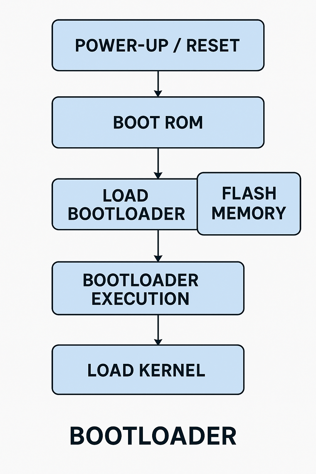
Simple Boot Process Using Flash Memory:
Here’s a very simplified sequence of the boot process when using flash memory:
Power-On → Boot ROM → Load Bootloader (from Flash) → Bootloader Executes → Load Kernel (from Flash) → Boot OS
In Detail:
- Power-On: System powers up, and the CPU starts from ROM.
- Boot ROM: The Boot ROM checks for valid bootloader code in the flash memory.
- Bootloader Loads: The bootloader (e.g., U-Boot) is loaded into RAM.
- Bootloader Initialization: The bootloader configures hardware and prepares the system for loading the OS.
- Load Kernel: The bootloader reads the kernel image from flash and loads it into RAM.
- OS Control: The bootloader transfers control to the kernel, and the operating system begins running.
Flash Memory and Security:
To ensure that the boot process is secure and unmodified, you can implement Secure Boot. This ensures that only trusted bootloader and kernel images are loaded from flash memory. It typically involves digital signatures to verify the integrity of the bootloader and OS image.
Real Example with U-Boot for Flash Memory:
Let’s walk through a basic process of using U-Boot to load the OS from flash memory:
1. Prepare U-Boot Configuration
In your u-boot/configs directory, configure the board for flash memory:
make am335x_evm_defconfig
Modify the U-Boot configuration for flash memory access (for example, for NAND):
make menuconfig
# Enable NAND and configure memory
2. Build U-Boot
Now, build the U-Boot image for your system:
make CROSS_COMPILE=arm-linux-gnueabihf- u-boot.bin
3. Flash U-Boot to NAND/NOR
Use a flashing tool to program U-Boot to the flash memory:
sudo dd if=u-boot.bin of=/dev/nand1 bs=512 seek=1
4. Verify Boot Process
Once U-Boot is installed, power on the device. It should automatically load the OS (or kernel) from flash memory.
Frequently Asked Questions (FAQs)
Q: What is the difference between U-Boot and BIOS?
A: BIOS is for PCs; U-Boot is for embedded systems. Both initialize hardware and boot the OS.
Q: Can U-Boot run scripts?
A: Yes, using environment variables and run command.
Q: Is U-Boot customizable?
A: Yes! It’s open source, so you can add/remove features and drivers.
Key Takeaways:
- Bootloaders load your OS/kernel from flash memory.
- Flash Memory is non-volatile, making it perfect for boot storage.
- U-Boot is commonly used as a bootloader for embedded systems.
- Secure Boot adds authentication to make sure only trusted code is run.
You can also Visit other tutorials of Embedded Prep
- What is eMMC (Embedded MultiMediaCard) memory ?
- Top 30+ I2C Interview Questions
- Bit Manipulation Interview Questions
- Structure and Union in c
- Little Endian vs. Big Endian: A Complete Guide
- Merge sort algorithm
Special thanks to @mr-raj for contributing to this article on EmbeddedPrep
Mr. Raj Kumar is a highly experienced Technical Content Engineer with 7 years of dedicated expertise in the intricate field of embedded systems. At Embedded Prep, Raj is at the forefront of creating and curating high-quality technical content designed to educate and empower aspiring and seasoned professionals in the embedded domain.
Throughout his career, Raj has honed a unique skill set that bridges the gap between deep technical understanding and effective communication. His work encompasses a wide range of educational materials, including in-depth tutorials, practical guides, course modules, and insightful articles focused on embedded hardware and software solutions. He possesses a strong grasp of embedded architectures, microcontrollers, real-time operating systems (RTOS), firmware development, and various communication protocols relevant to the embedded industry.
Raj is adept at collaborating closely with subject matter experts, engineers, and instructional designers to ensure the accuracy, completeness, and pedagogical effectiveness of the content. His meticulous attention to detail and commitment to clarity are instrumental in transforming complex embedded concepts into easily digestible and engaging learning experiences. At Embedded Prep, he plays a crucial role in building a robust knowledge base that helps learners master the complexities of embedded technologies.