Design Architecture using UML Diagrams in Software Engineering : When it comes to building robust and maintainable software, having a clear understanding of design and architecture is crucial. The design phase translates system requirements into a blueprint, laying the foundation for code development. Architecture, on the other hand, outlines the overall structure and behavior of the system, ensuring it can meet both functional and non-functional requirements efficiently.
One powerful tool used in software design and architecture is the Unified Modeling Language (UML). UML provides a standard way to visualize the design of a system through different types of diagrams, each representing different aspects of the system. In this article, we will dive into four essential UML diagrams—Use Case, Class, Sequence, and Activity Diagrams—to understand how they help in the design and architecture of software systems.

Design Architecture using UML
1. Use Case Diagram
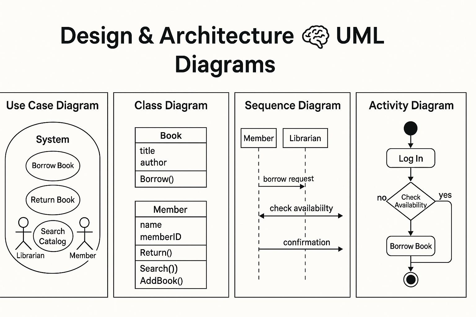
A Use Case Diagram is a visual representation of the system’s functional requirements. It shows the interactions between users (or other systems) and the system itself. These interactions are represented as use cases, which depict specific tasks or operations that the system can perform.
Components:
- Actors: Represent the external entities (users or systems) that interact with the system.
- Use Cases: Represent the various functions or processes that the system performs in response to the actors’ actions.
- System Boundary: Defines the scope of the system, indicating what is inside the system and what lies outside.
Example:
Consider a Library Management System:
- Actors: Librarian, Member, Administrator.
- Use Cases: Borrow Book, Return Book, Add New Book, Search Catalog, Update Member Information.
The Use Case Diagram for this system would illustrate how each actor interacts with the system and the functionalities they can access.
2. Class Diagram 📦
A Class Diagram is one of the most important diagrams in object-oriented design. It provides a static view of the system by showing the classes, their attributes, methods, and the relationships between them.
Components:
- Classes: Represent the objects or entities in the system, defined by their attributes and methods.
- Associations: Indicate relationships between classes, such as one-to-one, one-to-many, or many-to-many.
- Inheritance: Denotes the relationship where one class (the subclass) inherits attributes and behaviors from another (the superclass).
- Multiplicity: Indicates how many instances of a class can be associated with an instance of another class.
Example:
For the Library Management System, the class diagram might include:
- Classes: Book, Member, Librarian, Transaction.
- Attributes: Book (title, author, ISBN), Member (name, membership ID), Transaction (date, book).
- Methods: Borrow(), Return(), Search().
3. Sequence Diagram ⏳
A Sequence Diagram provides a dynamic view of the system by showing how objects interact with each other in a particular scenario over time. It emphasizes the sequence of messages exchanged between objects to achieve a specific functionality.
Components:
- Objects: Represent the entities involved in the interaction.
- Messages: Represent the interactions between objects, typically method calls or data exchanges.
- Lifelines: Vertical dashed lines representing the time span during which an object exists in the interaction.
- Activation Bars: Rectangles on the lifeline, showing when an object is active and processing a message.
Example:
In the Library Management System, a sequence diagram might illustrate how a Member interacts with the system to borrow a book:
- The Member sends a borrow request to the Librarian object.
- The Librarian checks if the book is available.
- The Member receives confirmation, and the book is borrowed.
The sequence diagram ensures that the communication flow is understood and accurately modeled for that specific scenario.
4. Activity Diagram 🔄
An Activity Diagram models the workflow or the business process in the system. It shows the flow of control from one activity to another and helps in understanding the sequence of operations or the steps involved in a process.
Components:
- Activities: Represent tasks or actions performed in the system.
- Transitions: Indicate the flow between activities.
- Decision Nodes: Represent points where the flow splits based on a condition.
- Start/End Points: Indicate the entry and exit points of the activity.
Example:
For the Library Management System, an activity diagram for borrowing a book might include:
- Start: The member logs into the system.
- Decision: Check if the book is available.
- Yes: Proceed to borrow.
- No: End.
- Borrow Book: The system processes the borrow request.
- End: The transaction is complete.
Why Use UML Diagrams in Software Design?
- Visualization: UML diagrams provide a clear, graphical representation of a system, making it easier for stakeholders to understand the system’s design and architecture.
- Communication: They serve as a common language between developers, business analysts, designers, and clients, ensuring everyone is aligned.
- Documentation: UML diagrams help in documenting the design process, providing valuable references for future development or maintenance.
- Problem-solving: These diagrams help identify potential issues early in the design phase by visualizing complex relationships and interactions.
💛 Support Embedded Prep
If you find our tutorials helpful and want to support our mission of sharing high-quality embedded system knowledge, you can contribute by buying us a coffee. Every small contribution helps us keep creating valuable content for learners like you. ☕
Thank you for your support — it truly keeps Embedded Prep growing. 💻✨
UML State Machine Diagrams
In software and systems design, understanding how an object behaves in response to different events is crucial. This is where UML State Machine Diagrams come into play. These diagrams visualize how an object changes state based on events, helping designers model dynamic behaviors effectively.
What is a UML State Machine Diagram?
A UML (Unified Modeling Language) State Machine Diagram—also known as a statechart diagram—is used to describe the lifecycle of an object. It shows:
- Different states an object can occupy.
- Transitions between states triggered by events.
- Actions executed during state changes or while in a state.
These diagrams are particularly useful in real-time systems, embedded systems, protocols, workflow modeling, and any domain where the object’s state plays a key role.
Key Concepts and Terminology
1. State
A condition or situation during the life of an object where it satisfies some condition or waits for an event.
- Initial State: Represented by a filled black circle (
●). It marks the starting point of the state machine. - Final State: Represented by a bullseye (
◎). It indicates the end of the object’s lifecycle. - Composite State: A state that contains sub-states, useful for representing complex behavior.
- Substate: A state nested inside a composite state.
2. Transition
A directed arrow (→) that shows the movement from one state to another. It typically includes:
Event [Guard] / Action
- Event: The trigger for the transition.
- Guard (optional): A condition that must be true for the transition to occur.
- Action (optional): An operation that occurs during the transition.
3. Action vs Activity
- Action: Executes instantaneously as a result of a transition.
- Activity: Represents longer-running behavior during a state.
4. Entry/Exit Actions
entry / action: Executed when entering a state.exit / action: Executed when exiting a state.
Example: Turnstile System
Let’s model a simple turnstile gate:
States:
LockedUnlocked
Events:
Coin(inserted)Push(someone tries to go through)
State Machine Diagram:
● ───> Locked
       Coin / unlock
Locked ────────→ Unlocked
       Push / alarm
Unlocked ───────→ Locked
       Push / lock
◎
Description:
- Initially, the turnstile is
Locked. - Inserting a
Coinunlocks it. - A
Pushwithout a coin triggers analarm. - Once
Pushedin theUnlockedstate, it goes back toLocked.
When to Use State Machine Diagrams
Use state machine diagrams when:
- Modeling reactive systems that respond to external/internal events.
- Describing workflow systems, like approval processes or UI interactions.
- Visualizing protocols or communication sequences.
- Implementing finite state machines (FSMs) in embedded systems.
Best Practices
- Keep states simple and meaningful.
- Use guard conditions to handle conditional transitions.
- Prefer entry/exit actions for reusable logic.
- Break down complex systems using composite states.
- Ensure completeness—every event in a state should be handled or explicitly ignored.
Tools That Support UML State Diagrams
Popular modeling tools include:
- Visual Paradigm
- Lucidchart
- StarUML
- Enterprise Architect
- Draw.io
These tools often support code generation for certain languages based on the state machine logic.
Understanding Finite State Machines (FSM)
In computing and electronics, Finite State Machines (FSMs) are fundamental models used to design systems that react to inputs based on their current state. From vending machines to traffic lights and embedded systems, FSMs power countless real-world applications.
What is a Finite State Machine?
A Finite State Machine (FSM) is a computational model consisting of a finite number of states, transitions between those states, inputs that trigger transitions, and optional outputs. At any given time, the system is in exactly one state, and changes to another state based on inputs and predefined rules.
Key Components of FSM
- States: The various modes in which the machine can exist (e.g.,
Idle,Running,Stopped). - Initial State: The state where the system starts.
- Input: External data or events that trigger state transitions.
- Transition Function: Rules that define how the system moves from one state to another based on input.
- Final (Accepting) State (optional): A special state that indicates completion or acceptance.
- Output (for Mealy/Moore machines): The actions produced by the machine depending on its state or transition.
Types of Finite State Machines
1. Moore Machine
- Output depends only on the current state.
- Output is associated with the state.
2. Mealy Machine
- Output depends on both the current state and the input.
- Output is associated with transitions.
| Feature | Moore Machine | Mealy Machine |
|---|---|---|
| Output | Based on state | Based on state + input |
| Simplicity | Easier to design and debug | More responsive |
| States | May require more states | Can be more compact |
Real-World Example: Traffic Light Controller
States:
GreenYellowRed
Input:
- Timer
FSM Logic:
- Start in
Red. - After timer expires, go to
Green. - Then
Yellow. - Then back to
Red.
Transition Table:
| Current State | Input (Timer) | Next State | Output |
|---|---|---|---|
| Red | Expired | Green | Go |
| Green | Expired | Yellow | Slow Down |
| Yellow | Expired | Red | Stop |
Applications of FSM
FSMs are used in a wide variety of domains:
- Embedded Systems: Control units, protocol design, device firmware.
- Game Development: NPC behaviors, game states (e.g., Start, Play, Pause, Game Over).
- UI Navigation: Button clicks, menu transitions.
- Digital Circuits: Sequential logic design using flip-flops.
- Compilers: Lexical analysis using deterministic FSMs (DFAs).
FSM vs UML State Machine Diagram
While both model state behavior, they serve slightly different purposes:
| Aspect | FSM | UML State Machine Diagram |
|---|---|---|
| Usage | Code-level modeling | High-level design & documentation |
| Detail Level | Simple state-input-output logic | Detailed with entry/exit actions |
| Visual Representation | Typically tabular or minimalistic | Rich, diagrammatic (UML-based) |
| Support for Hierarchy | No (basic FSM) | Yes (composite, nested states) |
Benefits of Using FSMs
- Predictable Behavior: Every input has a well-defined outcome.
- Modularity: Easy to extend and maintain.
- Formal Verification: Well-suited for testing and validation.
- Code Generation: FSMs can be translated into actual program logic easily.
FSM in Embedded C Example
typedef enum { RED, GREEN, YELLOW } State;
State currentState = RED;

void timerExpired() {
    switch (currentState) {
        case RED: currentState = GREEN; break;
        case GREEN: currentState = YELLOW; break;
        case YELLOW: currentState = RED; break;
    }
}
Software Architecture Patterns
When building software — whether it’s a web app, an embedded system, or a desktop application — organizing the code in a clean, scalable way is critical. That’s where Software Architecture Patterns come into play.
Let’s explore the most common patterns:
1. Layered Architecture (aka n-tier Architecture)
What It Is:
This pattern organizes the system into layers. Each layer has a specific responsibility and only communicates with adjacent layers.
Typical Layers:
- Presentation Layer – UI, user interaction
- Application Layer – Coordinates business logic
- Business Logic Layer – Implements core rules and logic
- Data Access Layer – Handles storage and retrieval
Example:
Imagine a simple banking app:
- The UI shows account balance (Presentation)
- It asks the application layer to fetch it
- Business logic layer checks if the user is authenticated
- Data access layer gets balance from the database
Pros:
- Easy to understand and maintain
- Good separation of concerns
- Common in enterprise applications
Cons:
- Can become rigid; layers depend on each other too much
- Might have performance overhead
2. Modular Architecture
What It Is:
Breaks the system into independent modules that can be developed and deployed separately.
Each module has a clearly defined interface and can be reused or swapped without affecting the rest of the system.
Think of it like:
LEGO blocks — you can combine different pieces to build various things.
Example:
In an e-commerce platform:
- A Payment Module
- A User Authentication Module
- A Product Catalog Module
Each can be worked on independently by different teams.
Pros:
- High flexibility and reusability
- Easier testing and maintenance
- Ideal for microservices and plugin-based systems
Cons:
- Can be harder to integrate
- Requires careful interface design
3. Event-Driven Architecture
What It Is:
The system reacts to events. Components send and listen for events asynchronously.
Example:
In an IoT system:
- A sensor detects temperature rise and emits an event
- A controller receives the event and turns on a fan
Pros:
- Highly decoupled and scalable
- Works well in real-time systems
Cons:
- Difficult to debug
- Event flow can become complex
4. Microkernel Architecture (aka Plugin Architecture)
What It Is:
You build a core system and allow new features to be added as plugins without changing the core.
Example:
Think of a media player:
- The core handles playback
- Plugins add support for MP3, MP4, subtitles, streaming, etc.
Pros:
- Very extensible
- Good for systems that evolve over time
Cons:
- Plugin interactions can get messy
- Version management is tricky
5. Microservices Architecture
What It Is:
The application is split into small services, each running independently and communicating via APIs (usually HTTP/REST).
Example:
A ride-sharing app:
- A service for user profiles
- A service for ride matching
- A service for payment processing
Each can be scaled or updated without touching the others.
Pros:
- Flexible and scalable
- Independent deployment
Cons:
- Complex deployment and networking
- Requires DevOps maturity
6. Client-Server Architecture
What It Is:
Divides the system into clients (requesters) and servers (responders). The client asks for services; the server provides them.
Example:
A web browser (client) requests a web page from a web server.
Pros:
- Simple and widely used
- Centralized server simplifies management
Cons:
- Server is a single point of failure
- Limited scalability unless load-balanced
7. Service-Oriented Architecture (SOA)
What It Is:
An evolution of modular and client-server patterns where services expose well-defined interfaces and are loosely coupled.
It’s the architectural grandparent of microservices.
Example:
A travel booking platform with services for:
- Flight booking
- Hotel reservation
- Customer reviews
Each service communicates via a standard protocol (like SOAP or REST).
Pros:
- Reusability of services
- Technology-agnostic
Cons:
- Can become heavy with enterprise-level tools
- More suitable for large applications
Summary Table
| Pattern | Best For | Key Benefit |
|---|---|---|
| Layered | Web and enterprise apps | Clear separation of concerns |
| Modular | Embedded, large systems | High maintainability |
| Event-Driven | IoT, real-time apps | Decoupling and scalability |
| Microkernel | Extensible desktop apps | Easy feature addition |
| Microservices | Scalable cloud apps | Independent deployment |
| Client-Server | Web systems, databases | Centralized control |
| Service-Oriented (SOA) | Enterprise systems | Reusable, loosely coupled services |
When to Use Which?
- Use Layered if you’re starting small and want structure.
- Use Modular when building for flexibility and reuse.
- Use Microservices if scaling and team independence matter.
- Use Event-Driven for responsive, real-time behavior.
- Use Microkernel when plugins/extensions are core to your product.
- Use Client-Server for simple request-response setups.
- Use SOA for interoperable services in enterprise ecosystems.
Where We Design Architecture for Embedded and Real-Time System Design Concepts
Designing the architecture for embedded and real-time systems is a foundational step that determines how reliable, efficient, and responsive your system will be. Whether you’re building a microwave controller or an automotive ECU (Electronic Control Unit), understanding where and how the architecture is designed is crucial.
Let’s explore this step by step in a clear and beginner-friendly way.
What Is System Architecture?
System architecture is a high-level blueprint of how your system will work. It defines:
- What components your system will have (e.g., sensors, processors, actuators)
- How these components interact
- What software modules are needed
- How timing, memory, and communication will be handled
Think of it as drawing the floor plan before constructing a building. It helps avoid chaos later.
Where Does Architecture Design Fit in the Development Process?
Architecture design is done early in the development lifecycle, right after requirements are gathered. Here’s a simplified flow:
1. Requirements → 2. Architecture Design → 3. Detailed Design → 4. Implementation → 5. Testing → 6. Deployment
In embedded and real-time systems, early architecture design is critical because:
- Hardware choices might be fixed or constrained
- Timing and reliability requirements are strict
- You can’t afford delays or software crashes
Where Do We Design the Architecture?
We design embedded and real-time architecture in both hardware and software domains. Let’s break them down.
1. Hardware Architecture Design
Where?
- On paper (initially), then using tools like OrCAD, KiCAD, or Altium Designer
- Sometimes with simulation tools like Proteus or MATLAB Simulink
What is decided?
- Type of microcontroller or processor (e.g., ARM Cortex-M4, ESP32)
- Memory size (RAM, Flash)
- Input/output interfaces (GPIOs, UART, SPI, I2C, CAN)
- Power source and regulators
- Sensor and actuator connections
- Communication methods (Bluetooth, Ethernet, Wi-Fi)
Why important?
- This hardware becomes the foundation your software will run on
- Incorrect hardware decisions can lead to major rework
2. Software Architecture Design
Where?
- On UML tools (like Enterprise Architect, Lucidchart, or Visual Paradigm)
- In spreadsheets, flowcharts, or even code comments (early drafts)
- Often documented in Software Architecture Documents (SAD)
What is decided?
- Operating system: Bare-metal or RTOS (like FreeRTOS, QNX, VxWorks)
- Task or thread design: What tasks run, their priority, timing, and how they communicate
- Driver layers: HAL (Hardware Abstraction Layer), Middleware
- Application logic: State machines, interrupt handling, timers
- Memory map and stack/heap size
- Error handling, watchdog, fault tolerance
Why important?
- Ensures that real-time constraints (deadlines) are met
- Prevents bugs due to race conditions, priority inversion, or memory issues
Example: Real-Time Temperature Monitoring System
Let’s imagine designing the architecture for a system that reads temperature every second and triggers a fan if it crosses a threshold.
Hardware Architecture:
- Microcontroller: STM32F103 (ARM Cortex-M3)
- Sensor: DHT11
- Fan: Controlled by relay
- Power: 5V battery
Software Architecture:
- RTOS: FreeRTOS
- Tasks:
ReadTempTask: Reads temperature every 1 secControlFanTask: Checks temp and turns fan ON/OFF
- Communication: Queues between tasks
- Watchdog Timer: Ensures system restarts if a task hangs
Key Concepts in Real-Time Architecture Design
| Concept | Meaning | Why It Matters |
|---|---|---|
| Task Scheduling | How tasks are run and switched | Ensures real-time deadlines |
| Inter-task Communication | How tasks talk (queues, semaphores) | Avoids data corruption |
| Interrupt Handling | Responding to external events | Needs to be fast and safe |
| Memory Management | RAM, stack, heap usage | Prevent crashes and overflows |
| Determinism | Predictable execution timing | Core to real-time guarantees |
Common Mistakes in Architecture Design
- Not considering real-time constraints early
- Overloading the main loop without RTOS
- Using too much memory or dynamic allocation
- No fallback or error handling
- Poor separation between hardware and application logic
Tools That Help Design Architecture
| Purpose | Tool Examples |
|---|---|
| Drawing Diagrams | Lucidchart, Draw.io, Microsoft Visio |
| UML & Modeling | Enterprise Architect, Modelio |
| Hardware Design | KiCAD, Altium, Proteus |
| Real-time Modeling | Simulink, Rhapsody |
| Code & Documentation | Doxygen, Git, VS Code |
Conclusion
Designing the architecture for embedded and real-time systems is not just a planning step—it’s the foundation for everything that follows. Whether you’re working with a simple microcontroller or a complex automotive system, good architecture:
- Saves time
- Reduces bugs
- Ensures deadlines are met
- Makes your system scalable and maintainable
Start simple, think in blocks, document your design, and always validate your real-time needs.
You can also Visit other tutorials of Embedded Prep
- What is eMMC (Embedded MultiMediaCard) memory ?
- Top 30+ I2C Interview Questions
- Bit Manipulation Interview Questions
- Structure and Union in c
- Little Endian vs. Big Endian: A Complete Guide
- Merge sort algorithm
Special thanks to @mr-raj for contributing to this article on EmbeddedPr
Mr. Raj Kumar is a highly experienced Technical Content Engineer with 7 years of dedicated expertise in the intricate field of embedded systems. At Embedded Prep, Raj is at the forefront of creating and curating high-quality technical content designed to educate and empower aspiring and seasoned professionals in the embedded domain.
Throughout his career, Raj has honed a unique skill set that bridges the gap between deep technical understanding and effective communication. His work encompasses a wide range of educational materials, including in-depth tutorials, practical guides, course modules, and insightful articles focused on embedded hardware and software solutions. He possesses a strong grasp of embedded architectures, microcontrollers, real-time operating systems (RTOS), firmware development, and various communication protocols relevant to the embedded industry.
Raj is adept at collaborating closely with subject matter experts, engineers, and instructional designers to ensure the accuracy, completeness, and pedagogical effectiveness of the content. His meticulous attention to detail and commitment to clarity are instrumental in transforming complex embedded concepts into easily digestible and engaging learning experiences. At Embedded Prep, he plays a crucial role in building a robust knowledge base that helps learners master the complexities of embedded technologies.