Author: admin

  • Power Management in an RTOS: Optimizing Power Consumption in Resource-Constrained Systems | Master RTOS Interview Questions (2026)

    Power Management in an RTOS : Learn power management in RTOS and how it helps optimize power consumption in resource-constrained systems. Explore techniques like tickless idle mode, DVFS, and task scheduling for energy-efficient embedded systems.

    In today’s world of embedded systems, efficiency is not just about speed and performance but also about power management. Many devices, such as IoT sensors, medical devices, wearables, and automotive systems, operate on limited power sources like batteries. This makes power optimization in RTOS (Real-Time Operating Systems) a critical aspect of system design.

    In this article, we’ll explain the concept of power management in an RTOS, why it is important, and how an RTOS can help reduce power consumption in resource-constrained systems.

    What is Power Management in an RTOS?

    Power management in an RTOS refers to techniques and strategies used to reduce energy usage while still meeting the real-time performance requirements of tasks. Since an RTOS is designed to manage tasks with precise timing, it must ensure that low-power techniques do not interfere with task deadlines.

    The goal is to balance performance and energy efficiency so that the system can run longer without draining the battery, especially in embedded systems with limited resources.

    Why is Power Management Important in Resource-Constrained Systems?

    Resource-constrained systems, such as wearables, remote sensors, and portable medical devices, often have:

    • Limited battery capacity
    • Small processing power
    • Restricted memory and storage

    Without proper power management, these devices may quickly drain energy, leading to reduced usability or frequent recharging. Efficient power consumption optimization in RTOS ensures reliability, longer device life, and better user experience.

    How an RTOS Optimizes Power Consumption

    An RTOS (Real-Time Operating System) provides multiple techniques to manage and optimize power usage in embedded systems:

    1. Task Scheduling for Low Power

    The RTOS scheduler can intelligently manage CPU usage by allowing the processor to enter idle or sleep modes when no critical tasks are running. This reduces unnecessary power drain.

    2. Dynamic Voltage and Frequency Scaling (DVFS)

    Some RTOS implementations support DVFS, where the processor dynamically adjusts its voltage and clock speed based on workload. Lowering the frequency during light tasks reduces power consumption significantly.

    3. Tickless Idle Mode

    Traditional RTOS kernels use periodic tick interrupts, which prevent the processor from entering deep sleep. A tickless RTOS disables unnecessary ticks and only wakes the CPU when required, saving energy.

    4. Peripheral Power Control

    RTOS can manage hardware peripherals (like UART, I2C, SPI, or sensors) by turning them off or placing them in low-power mode when not in use.

    5. Event-Driven Execution

    Instead of continuous polling, RTOS-based applications can use interrupt-driven execution. The CPU sleeps until an event (like sensor input) occurs, conserving power.

    6. Energy-Aware Task Design

    Developers can design tasks in such a way that they consume minimal CPU cycles, use efficient algorithms, and avoid unnecessary wake-ups.

    Real-World Example of Power Management in RTOS

    • IoT Devices: A temperature sensor with an RTOS may stay in deep sleep for most of the time, only waking up every few minutes to collect data and transmit it.
    • Wearables: Smartwatches running on an RTOS use tickless idle mode and DVFS to balance performance and battery life.

    How RTOS Optimizes Power Consumption in Embedded Systems

    Example 1: Using Idle Hook for Power Saving

    Most RTOSes let you define an Idle Hook – code that runs when no task is ready. This is a good place to put the CPU in low-power mode.

    #include "FreeRTOS.h"
    #include "task.h"
    
    // Idle Hook function (called when no task is running)
    void vApplicationIdleHook(void)
    {
        // Enter low-power sleep mode until an interrupt occurs
        __asm volatile("WFI");   // Wait For Interrupt instruction
    }
    

    ✅ Here, the CPU automatically wakes up when a timer interrupt or external event happens.

    Example 2: Tickless Idle Mode in FreeRTOS

    Tickless idle allows the RTOS to stop the SysTick timer when the system is idle.

    // In FreeRTOSConfig.h enable tickless idle
    #define configUSE_TICKLESS_IDLE    1
    #define configEXPECTED_IDLE_TIME_BEFORE_SLEEP   2
    
    // Optional: implement custom pre-sleep and post-sleep functions
    void vPreSleepProcessing(uint32_t ulExpectedIdleTime)
    {
        // Put peripherals into low power mode before sleep
        // Example: disable ADC, UART, etc.
    }
    
    void vPostSleepProcessing(uint32_t ulExpectedIdleTime)
    {
        // Re-enable peripherals after waking up
    }
    

    ✅ This prevents the CPU from waking up on every tick and only wakes when an actual event or timer expires.

    Example 3: Peripheral Power Gating

    You can turn off unused peripherals when not needed.

    void disableUnusedPeripherals(void)
    {
        // Example for STM32 MCU
        RCC->APB1ENR &= ~(RCC_APB1ENR_USART2EN); // Disable UART2
        RCC->APB2ENR &= ~(RCC_APB2ENR_ADC1EN);   // Disable ADC1
    }
    
    void enablePeripherals(void)
    {
        RCC->APB1ENR |= RCC_APB1ENR_USART2EN;    // Enable UART2
        RCC->APB2ENR |= RCC_APB2ENR_ADC1EN;      // Enable ADC1
    }
    

    ✅ Saving power by shutting down unused hardware blocks.

    Example 4: Dynamic Voltage and Frequency Scaling (DVFS)

    If the MCU supports clock scaling, you can lower CPU frequency when workload is low.

    void setLowPowerClock(void)
    {
        // Example: Switch to low-speed internal oscillator
        RCC->CFGR |= RCC_CFGR_SW_HSI; 
    }
    
    void setHighPerformanceClock(void)
    {
        // Example: Switch back to high-speed external oscillator
        RCC->CFGR |= RCC_CFGR_SW_HSE;
    }
    

    RTOS tasks can request high-performance or low-power modes depending on workload.

    ✨ In practice, RTOS-based power management usually combines idle hooks + tickless idle + peripheral gating + clock scaling to optimize energy use.

    FAQ on Power Management in RTOS

    Q1. What is power management in an RTOS?

    Ans: Power management in an RTOS (Real-Time Operating System) refers to the techniques and features used to minimize energy consumption of embedded devices while still meeting real-time deadlines. It involves controlling CPU modes, peripheral activity, and task scheduling to save energy.

    Q2. Why is power management important in resource-constrained systems?

    Ans: Resource-constrained systems, such as IoT devices, wearables, and battery-powered sensors, have limited energy sources. Without efficient power management, these devices may drain batteries quickly or generate unnecessary heat. Power optimization extends battery life and improves system reliability.

    Q3. How does an RTOS help reduce power consumption?

    Ans:
    An RTOS reduces power usage by:
    a) Putting the CPU into low-power or sleep states when no critical tasks are running.
    b) Dynamically adjusting clock speeds (Dynamic Voltage and Frequency Scaling).
    c) Scheduling tasks efficiently so that idle periods can be maximized.
    d) Shutting down unused peripherals automatically.

    Q4. What are the common techniques of power management in RTOS?

    Ans:
    Some widely used techniques include:
    a) Dynamic Voltage and Frequency Scaling (DVFS) – adjusting CPU speed based on workload.
    b) Tickless Idle Mode – disabling the periodic timer tick when the system is idle.
    c) Peripheral Power Gating – turning off hardware components not in use.
    d) Sleep Modes – multiple levels of low-power states for the processor.

    Q5. What is the role of tickless idle in power optimization?

    Ans: In a traditional RTOS, the CPU wakes up at every system tick, even if no task needs attention, wasting energy. Tickless idle mode allows the RTOS to stop the periodic tick timer during idle periods and only wake the CPU when an event or interrupt occurs. This significantly lowers energy consumption.

    Q6. How does task scheduling impact power consumption?

    Ans: Efficient scheduling ensures tasks are executed in minimal time, leaving more idle periods for the CPU to enter low-power states. Poor scheduling may keep the processor active unnecessarily, leading to higher power usage.

    Q7. Can power management affect system performance?

    Ans: Yes, if not carefully implemented. Aggressive power-saving techniques like lowering CPU frequency may increase task execution time, potentially missing real-time deadlines. Therefore, RTOS-based power management must balance performance and energy efficiency.

    Q8. What are examples of real-world systems using RTOS power management?

    Ans:
    a) Wearables (smartwatches, fitness bands) – need long battery life.
    b) IoT sensors – often battery-powered, deployed in remote areas.
    c) Automotive ECUs – manage power states when the vehicle is idle or running.
    d) Medical devices – must run efficiently for extended periods without frequent charging.

    Q9. What challenges exist in RTOS power management?

    Ans: Challenges include:
    a) Maintaining real-time deadlines while saving energy.
    b) Managing diverse peripherals with different power states.
    c) Balancing performance requirements with energy budgets.
    d) Hardware dependency, since low-power features vary by microcontroller.

    Q10. How can developers implement power management in their RTOS applications?

    Ans: Developers can:
    a) Use RTOS APIs for sleep modes and idle hooks.
    b) Configure tickless idle mode.
    c) Profile energy consumption to identify bottlenecks.
    d) Apply workload-aware scheduling.
    e) Leverage hardware-specific low-power features provided by the MCU vendor .

    Conclusion

    Power management in an RTOS is essential for building energy-efficient embedded systems. By using techniques like task scheduling, tickless idle mode, dynamic voltage scaling, and peripheral control, an RTOS ensures devices consume minimal power while still meeting real-time requirements.

    For resource-constrained systems, this not only improves battery life but also makes the system more reliable and cost-effective. As embedded systems continue to expand into IoT, automotive, and medical devices, mastering RTOS power optimization becomes a key skill for developers.

    Power Management in an RTOS
    Power Management in an RTOS Optimizing Power Consumption in Resource-Constrained Systems Master RTOS Interview Questions (2025)
  • Inter-Task Communication in RTOS: Concepts, Mechanisms, and Examples | Master RTOS Interview Questions (2026)

    Inter-Task Communication : In real-time operating systems (RTOS), multiple tasks often need to exchange information to function correctly and maintain system reliability. This process is known as inter-task communication (ITC). Effective ITC ensures that tasks can coordinate their actions, share data safely, and avoid issues like data corruption or priority inversion.

    What is Inter-Task Communication (ITC) in RTOS?

    Inter-task communication is the method by which different tasks (or threads) running in an RTOS exchange information. Unlike general-purpose operating systems, RTOS emphasizes deterministic behavior and timely execution. Therefore, ITC mechanisms in RTOS must be fast, reliable, and predictable.

    Why is Inter-Task Communication Important?

    1. Data Sharing: Tasks often need to access or update shared data.
    2. Synchronization: Some tasks may need to wait for events or signals from other tasks.
    3. Resource Management: Helps in managing access to shared hardware resources without conflicts.
    4. Event Notification: Allows tasks to notify others about the occurrence of specific events.

    Common Inter-Task Communication Mechanisms

    RTOS provides multiple mechanisms for inter-task communication. Each has its own use case and advantages.

    1. Message Queues

    • Concept: A message queue is a buffer that stores messages sent by one task and received by another.
    • Features: FIFO (First-In-First-Out) order, optional priority-based message handling.
    • Use Case: Ideal for sending structured data between producer and consumer tasks.
    • Example (Pseudo Code):
    // Producer task
    msg = "Sensor Data";
    sendMessage(queue, msg);
    
    // Consumer task
    receivedMsg = receiveMessage(queue);
    processData(receivedMsg);
    

    2. Semaphores

    • Concept: A semaphore is a signaling mechanism used for synchronization. It can be binary (0 or 1) or counting.
    • Features: Prevents race conditions by controlling task access to shared resources.
    • Use Case: Protecting a shared resource like a hardware peripheral.
    • Example (Pseudo Code):
    // Task A
    wait(semaphore); // wait until available
    accessResource();
    signal(semaphore); // release resource
    

    3. Mutexes (Mutual Exclusion)

    • Concept: A mutex is similar to a binary semaphore but designed specifically for mutual exclusion.
    • Features: Prevents priority inversion with priority inheritance mechanisms.
    • Use Case: Ensuring only one task accesses a critical section at a time.

    4. Event Flags / Event Groups

    • Concept: Event flags are bits used to signal the occurrence of specific events between tasks.
    • Features: Multiple tasks can wait for multiple events simultaneously.
    • Use Case: Signaling complex event patterns or task dependencies.

    5. Shared Memory

    • Concept: Tasks share a common memory region for direct data exchange.
    • Features: Fast, but requires synchronization (semaphore or mutex) to avoid race conditions.
    • Use Case: High-speed data transfer, such as sensor readings or buffers for audio/video streaming.

    Real-World Example

    Consider a drone system:

    • Sensor Task: Reads GPS and IMU data.
    • Control Task: Computes motor commands.
    • Communication Task: Sends telemetry data to the base station.

    Here, message queues can send sensor data from the Sensor Task to the Control Task, while event flags can notify the Communication Task whenever new telemetry data is ready to transmit.

    Conclusion

    Inter-task communication is a cornerstone of real-time systems. By using mechanisms like message queues, semaphores, mutexes, event flags, and shared memory, developers can ensure that tasks work together efficiently and safely. Understanding ITC not only improves system reliability but also enhances the predictability and performance of RTOS-based applications.

    FAQ Inter-Task Communication (ITC) in RTOS

    1) What is inter-task communication in an RTOS?

    Inter-task communication (ITC) is how tasks (threads) exchange data and coordinate actions. It covers two needs:

    • Data passing (e.g., sensor values from Producer → Consumer)
    • Synchronization (e.g., “I’m done, you can start”)

    2) Why not just use global variables?

    Unprotected globals cause race conditions, data corruption, and timing bugs. RTOS primitives (queues, semaphores, mutexes, etc.) provide atomicity, ordering, and blocking with timeouts.

    3) What are the most common ITC mechanisms?

    • Queues / Mailboxes / Message queues – pass data/messages in FIFO order.
    • Semaphores – signaling (binary) and counting (resource tokens).
    • Mutexes – mutual exclusion with priority inheritance for shared data.
    • Event flags (event groups) – bitwise signals; wait for any/all events.
    • Pipes/Streams – byte streams.
    • Shared memory + synchronization – fastest but you must lock correctly.
    • Message buffers/ring buffers – lightweight, often lock-free for single-producer/single-consumer.

    4) Queue vs. mailbox vs. message buffer—what’s the difference?

    • Queue: fixed-size slots; each item same size; strict FIFO.
    • Mailbox: like a queue but often single-slot or small count; can carry pointers.
    • Message buffer/stream: variable-length messages serialized into a FIFO buffer.

    5) When should I use a semaphore vs. a mutex?

    • Semaphore (binary): general signal (e.g., ISR → task) or counting for identical resources (N tokens).
    • Mutex: protect critical sections; supports priority inheritance to mitigate priority inversion.

    6) Can an ISR use these mechanisms?

    Yes, but only ISR-safe APIs (often suffixed with FromISR). Typically:

    • Give semaphores/queues to wake a task.
    • Keep ISR handlers short; move heavy work to a task.

    FreeRTOS example (ISR → Task using a binary semaphore):

    // Global
    SemaphoreHandle_t xSem;
    
    void ISR_Handler(void) {
        BaseType_t xHPW = pdFALSE;
        xSemaphoreGiveFromISR(xSem, &xHPW);
        portYIELD_FROM_ISR(xHPW);
    }
    
    void TaskWaiter(void *arg) {
        for (;;) {
            if (xSemaphoreTake(xSem, pdMS_TO_TICKS(50)) == pdTRUE) {
                // Handle the event
            } else {
                // Timeout handling
            }
        }
    }
    

    7) How do queues work in practice?

    A producer pushes data; a consumer blocks until data arrives or timeout expires.

    FreeRTOS queue example (Producer/Consumer):

    typedef struct { uint32_t ts; int16_t temp; } Sample_t;
    QueueHandle_t q;
    
    void Producer(void *arg) {
        Sample_t s;
        for (;;) {
            s.ts = xTaskGetTickCount();
            s.temp = read_temp();
            xQueueSend(q, &s, pdMS_TO_TICKS(10)); // non-blocking-ish
            vTaskDelay(pdMS_TO_TICKS(100));
        }
    }
    
    void Consumer(void *arg) {
        Sample_t s;
        for (;;) {
            if (xQueueReceive(q, &s, portMAX_DELAY) == pdTRUE) {
                process_sample(s);
            }
        }
    }
    

    8) What are event flags and when should I use them?

    Event flags are bits representing conditions (BIT0, BIT1, …). Tasks can wait for any or all bits, optionally with clear-on-exit. Great for multi-source synchronization without moving data.

    FreeRTOS EventGroup example:

    #define EVT_WIFI (1<<0)
    #define EVT_TIME (1<<1)
    
    EventGroupHandle_t eg;
    
    void TaskCoordinator(void *arg) {
        EventBits_t bits = xEventGroupWaitBits(eg, EVT_WIFI|EVT_TIME, pdTRUE, pdTRUE, portMAX_DELAY);
        // Runs when both Wi-Fi ready and time synced
    }
    

    9) What’s priority inversion and how do I avoid it?

    A low-priority task holds a lock needed by a high-priority task, causing the high-priority task to wait behind a medium-priority task. Use mutexes with priority inheritance (not semaphores) for shared data.

    10) What’s the best way to pass large data (e.g., frames)?

    Pass pointers through a queue/mailbox to pre-allocated buffers (from a memory pool) instead of copying big payloads. This is a zero-copy pattern. Guard the buffer lifetime (who owns/free’s it).

    11) How do timeouts help reliability?

    Every blocking call should have a finite timeout to avoid deadlocks and detect stalls. On timeout, log, count errors, and apply recovery (reset peripheral, drop message, escalate).

    12) How big should my queue be?

    Profile producer/consumer rates and worst-case bursts. Rule of thumb:

    depth ≥ (burst size) + (max producer - consumer backlog during blocking)
    

    Add margin for jitter; monitor queue high-water mark at runtime.

    13) Can I use shared memory without locks if I’m careful?

    Only in single-producer/single-consumer with a lock-free ring buffer and proper volatile/compiler barriers or RTOS primitives. For multi-producer or multi-consumer, use locks or specialized lock-free structures.

    14) Are message queues deterministic enough for hard real-time?

    Yes—if sized properly, with bounded operations, ISR-safe signaling, and no dynamic allocation in the hot path. Avoid variable-time copies; prefer fixed sizes or zero-copy pools.

    15) What’s the difference between blocking and non-blocking APIs?

    • Blocking waits until success/timeout; simpler logic but can delay tasks.
    • Non-blocking returns immediately; requires retries or event-driven designs.

    Use blocking with sensible timeouts for simplicity; use non-blocking in high-rate pipelines.

    16) How do I choose between queues and event flags?

    • Need to carry data? → Queue/Message buffer
    • Need to signal states or gate progress? → Semaphore/Event flags
      Often you’ll signal with an event and then read from a shared buffer.

    17) Example with POSIX message queues (RTOSes with POSIX layer)

    #include <mqueue.h>
    typedef struct { int id; float val; } msg_t;
    
    mqd_t mq;
    struct mq_attr attr = { .mq_flags=0, .mq_maxmsg=8, .mq_msgsize=sizeof(msg_t), .mq_curmsgs=0 };
    
    void setup() {
        mq = mq_open("/sensorq", O_CREAT | O_RDWR, 0644, &attr);
    }
    
    void producer() {
        msg_t m = { .id=1, .val=3.14f };
        mq_timedsend(mq, (char*)&m, sizeof(m), 0, &(struct timespec){.tv_sec=0,.tv_nsec=1000000});
    }
    
    void consumer() {
        msg_t m;
        ssize_t n = mq_timedreceive(mq, (char*)&m, sizeof(m), NULL, &(struct timespec){.tv_sec=1,0});
        if (n > 0) handle(m);
    }
    

    18) How do I debug ITC issues?

    • Enable RTOS trace hooks and queue/semaphore stats.
    • Log timeouts, drops, queue depths.
    • Add asserts on return codes.
    • Use watchpoints on shared buffers and stack watermarking.

    19) What pitfalls should I avoid?

    • Using a binary semaphore as a lock (use a mutex).
    • Dynamic allocation in ISR or hot loops → fragmentation/jitter.
    • Unbounded message sizes or unvalidated pointers.
    • Forgetting ownership—who frees a message buffer?
    • Ignoring priority inheritance → inversion.

    20) What’s a clean architecture for ITC in embedded apps?

    • Drivers/ISRs push events or buffer pointers to queues.
    • Workers process and publish results via queues/mailboxes.
    • Supervisors wait on event groups and orchestrate modes.
    • Shared data guarded by mutexes; larger payloads via memory pools.
  • Fixed-Priority Scheduling vs Dynamic-Priority Scheduling | Master RTOS Interview Questions (2026)

    Fixed-Priority Scheduling vs Dynamic-Priority Scheduling : Learn the difference between fixed-priority scheduling and dynamic-priority scheduling in RTOS. Understand advantages, disadvantages, examples, and real-world applications of Rate Monotonic Scheduling (RMS) and Earliest Deadline First (EDF) for hard and soft real-time systems.

    Introduction of Fixed-Priority Scheduling vs Dynamic-Priority Scheduling

    In the world of Real-Time Operating Systems (RTOS), task scheduling is one of the most important concepts. Scheduling decides which task should run, when it should run, and for how long. Since real-time systems deal with time-sensitive operations, choosing the right scheduling algorithm is critical.

    Two of the most widely used scheduling techniques in RTOS are:

    • Fixed-Priority Scheduling (FPS)
    • Dynamic-Priority Scheduling (DPS)

    In this article, we will understand both methods, their advantages, disadvantages, and real-world applications, with easy-to-follow examples.

    What is Fixed-Priority Scheduling?

    In fixed-priority scheduling, each task is assigned a priority when it is created, and this priority does not change throughout the execution. The RTOS scheduler always picks the task with the highest priority among the ready tasks.

    ✅ A common fixed-priority algorithm is Rate Monotonic Scheduling (RMS), where tasks with shorter periods (more frequent tasks) are given higher priority.

    Example

    Imagine you have three tasks in an automotive ECU system:

    • Engine Control Task (high priority)
    • Airbag Monitoring Task (medium priority)
    • Infotainment Display Task (low priority)

    Here, the engine control must always run first because it is critical for vehicle safety. Even if the infotainment task is ready, it must wait until the higher-priority tasks finish.

    What is Dynamic-Priority Scheduling?

    In dynamic-priority scheduling, the priority of tasks can change at runtime depending on factors like deadlines, waiting time, or system load.

    ✅ A well-known dynamic scheduling algorithm is Earliest Deadline First (EDF), where the task with the closest deadline is scheduled first.

    Example

    Imagine a video streaming system:

    • Frame Decoding Task (deadline soon)
    • Buffer Management Task (deadline later)

    Here, the frame decoding must be done immediately, otherwise the video will lag. So its priority is increased dynamically, and the system executes it first.

    Advantages and Disadvantages

    FeatureFixed-Priority Scheduling (FPS)Dynamic-Priority Scheduling (DPS)
    SimplicitySimple and easy to implement.More complex; requires priority recalculation.
    OverheadLow overhead, fast decisions.Higher overhead due to frequent updates.
    PredictabilityHighly predictable, good for safety-critical systems.Less predictable since priorities change.
    CPU UtilizationMay underutilize CPU.Better CPU utilization, can achieve near 100%.
    StarvationRisk of low-priority tasks being starved.Reduced starvation, since tasks get priority boosts.
    Best suited forHard real-time systems like automotive ECUs, avionics, medical devices.Soft real-time systems like multimedia, networking, telecom.

    Code Example: Fixed vs Dynamic Scheduling

    Here’s a simple C++ simulation that shows both approaches:

    #include <iostream>
    #include <queue>
    #include <vector>
    using namespace std;
    
    struct Task {
        string name;
        int exec_time;
        int deadline;
        int priority;
    };
    
    // Comparator for Fixed Priority Scheduling
    struct FixedPriority {
        bool operator()(Task const& a, Task const& b) {
            return a.priority < b.priority; // higher number = higher priority
        }
    };
    
    // Comparator for Dynamic Priority Scheduling (EDF)
    struct DynamicPriority {
        bool operator()(Task const& a, Task const& b) {
            return a.deadline > b.deadline; // smaller deadline first
        }
    };
    
    int main() {
        vector<Task> tasks = {
            {"Task A", 200, 3, 3},
            {"Task B", 300, 5, 2},
            {"Task C", 100, 8, 1}
        };
    
        priority_queue<Task, vector<Task>, FixedPriority> fixedQ(tasks.begin(), tasks.end());
        priority_queue<Task, vector<Task>, DynamicPriority> dynamicQ(tasks.begin(), tasks.end());
    
        cout << "--- Fixed Priority Scheduling ---\n";
        while (!fixedQ.empty()) {
            Task t = fixedQ.top(); fixedQ.pop();
            cout << "Running " << t.name << " (priority=" << t.priority << ")\n";
        }
    
        cout << "\n--- Dynamic Priority Scheduling ---\n";
        while (!dynamicQ.empty()) {
            Task t = dynamicQ.top(); dynamicQ.pop();
            cout << "Running " << t.name << " (deadline=" << t.deadline << ")\n";
        }
    }
    

    Example Output

    --- Fixed Priority Scheduling ---
    Running Task A (priority=3)
    Running Task B (priority=2)
    Running Task C (priority=1)
    
    --- Dynamic Priority Scheduling ---
    Running Task A (deadline=3)
    Running Task B (deadline=5)
    Running Task C (deadline=8)
    

    This shows how the same set of tasks are executed differently depending on whether priorities are fixed or dynamic.

    Real-World Applications

    • Fixed-Priority Scheduling:
      • Automotive ECUs (Engine Control, ABS, Airbag systems)
      • Medical devices (Pacemakers, Infusion pumps)
      • Avionics systems (Flight control computers)
    • Dynamic-Priority Scheduling:
      • Multimedia systems (Video/Audio streaming)
      • Networking protocols (Packet scheduling, QoS)
      • Cloud systems (Dynamic resource allocation)

    Conclusion

    Both fixed-priority scheduling and dynamic-priority scheduling have their own place in RTOS design.

    • If your system is hard real-time and requires predictability, go with Fixed-Priority Scheduling.
    • If your system is soft real-time and requires better CPU utilization and flexibility, choose Dynamic-Priority Scheduling.

    By understanding these techniques, embedded engineers can make better design choices and build reliable real-time applications

    Frequently Asked Questions (FAQ)

    1. What is fixed-priority scheduling in RTOS?

    Fixed-priority scheduling is a method where each task is assigned a priority at the time of creation, and this priority never changes. The scheduler always picks the task with the highest fixed priority. A common example is Rate Monotonic Scheduling (RMS).

    2. What is dynamic-priority scheduling in RTOS?

    Dynamic-priority scheduling is a method where the priority of tasks changes during runtime depending on deadlines, waiting time, or system load. A popular algorithm for this approach is Earliest Deadline First (EDF).

    3. Which is better: fixed-priority scheduling or dynamic-priority scheduling?

    It depends on the application:

    • Fixed-priority scheduling is better for hard real-time systems like automotive ECUs, avionics, and medical devices where predictability is critical.
    • Dynamic-priority scheduling is better for soft real-time systems like video streaming, networking, and telecom where CPU utilization and flexibility are more important.

    4. What are the disadvantages of fixed-priority scheduling?

    • Lower-priority tasks may face starvation if higher-priority tasks always occupy the CPU.
    • CPU utilization may not be optimal.
    • Not flexible for dynamic workloads.

    5. What are the disadvantages of dynamic-priority scheduling?

    • More complex to implement.
    • Higher overhead since priorities must be recalculated frequently.
    • Less predictable compared to fixed-priority scheduling.

    6. Is Rate Monotonic Scheduling (RMS) fixed or dynamic?

    Rate Monotonic Scheduling (RMS) is a fixed-priority scheduling algorithm. Tasks with shorter periods (more frequent tasks) are assigned higher priority.

    7. Is Earliest Deadline First (EDF) fixed or dynamic?

    Earliest Deadline First (EDF) is a dynamic-priority scheduling algorithm. Tasks with the nearest deadline are given the highest priority.

    8. Which scheduling method gives better CPU utilization?

    Dynamic-priority scheduling (EDF) generally achieves better CPU utilization compared to fixed-priority scheduling. EDF can theoretically reach 100% CPU utilization, while RMS guarantees schedulability only up to around 69% utilization for multiple tasks.

    9. Where is fixed-priority scheduling used in real life?

    • Automotive: Engine Control, ABS, Airbags
    • Aerospace: Flight Control Systems
    • Medical: Pacemakers, Infusion Pumps

    10. Where is dynamic-priority scheduling used in real life?

    • Multimedia: Audio/Video playback and streaming
    • Networking: Packet scheduling, Quality of Service (QoS)
    • Cloud Systems: Dynamic workload allocation
  • How Does an RTOS Handle Interrupts and Manage Interrupt Service Routines (ISRs)? | Master RTOS Interview Questions (2026)

    RTOS Handle Interrupts : When working with embedded systems, the ability to respond quickly to external events is crucial. This is where RTOS interrupts and ISRs (Interrupt Service Routines) come into play. An RTOS (Real-Time Operating System) is specifically designed to handle interrupts efficiently and ensure predictable, low-latency responses to hardware events.

    In this article, we’ll explore what interrupts are, how ISRs work, and how an RTOS manages them step by step with examples.

    RTOS Handle Interrupts

    What Are Interrupts in an RTOS?

    An interrupt is a hardware-generated signal that tells the CPU to stop its current task and immediately handle a new event. For example:

    • A timer interrupt triggers the scheduler to switch tasks.
    • A UART interrupt signals the arrival of new serial data.
    • A GPIO interrupt detects a button press.

    Without interrupts, the CPU would have to constantly check for events (polling), which is inefficient and wastes processing time.

    What Is an Interrupt Service Routine (ISR)?

    An ISR (Interrupt Service Routine) is a special function that runs whenever an interrupt occurs. It is executed in interrupt context, which means:

    • It runs with higher priority than normal tasks.
    • It should be fast and lightweight.
    • It cannot perform blocking operations (like waiting for a semaphore indefinitely).

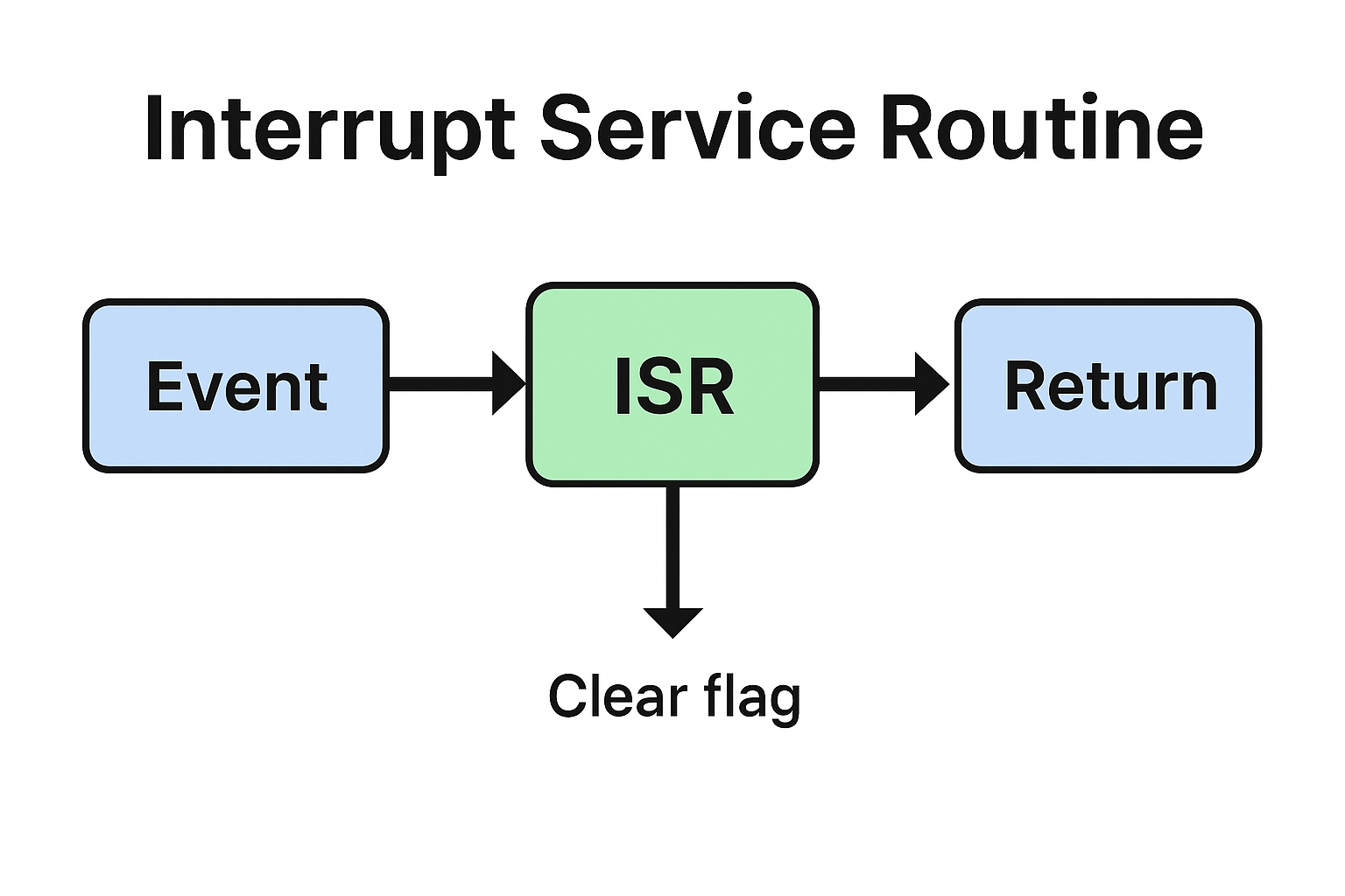
    Instead of doing heavy work, an ISR usually just:

    1. Reads or writes data from a hardware register.
    2. Clears the interrupt flag.
    3. Notifies a task to handle detailed processing later.

    How RTOS Handles Interrupts (Step by Step)

    Let’s break down the lifecycle of RTOS interrupts and ISRs:

    Step 1: Interrupt Trigger

    • A hardware event (like timer overflow or data received) raises an interrupt request.
    • CPU looks up the ISR address from the Interrupt Vector Table (IVT).
    • CPU saves the current execution context (registers, program counter, status flags).

    Step 2: ISR Execution

    • ISR immediately takes control.
    • ISR performs minimal operations:
      • Reads sensor/communication data.
      • Clears interrupt flags.
      • Signals the RTOS if further processing is required.

    Step 3: Deferring Work to Tasks

    • Since ISRs must be short, most RTOSes provide mechanisms to delegate work:
      • Semaphores – ISR gives a semaphore to wake a task.
      • Queues – ISR sends data to a queue for task processing.
      • Event Flags – ISR sets an event flag that tasks monitor.

    Step 4: Task Scheduling After ISR

    • If an ISR unblocks a higher-priority task, the RTOS can immediately switch context to that task.
    • Otherwise, the interrupted task resumes execution.

    This ensures deterministic and low-latency event handling.

    RTOS Management of ISRs

    Rules for Writing ISRs in RTOS:

    • Keep them short and fast.
    • Avoid using blocking calls.
    • Use ISR-safe RTOS APIs (like xQueueSendFromISR() in FreeRTOS).

    Advanced Features in RTOS:

    • Interrupt Nesting: Higher-priority interrupts can preempt lower-priority ISRs.
    • Critical Sections: RTOS provides APIs to protect shared data between ISRs and tasks.
    • Context Switching from ISR: RTOS can trigger a scheduler immediately after ISR execution if needed.

    Example: ISR Handling in FreeRTOS

    // ISR: UART interrupt handler
    void UART_IRQHandler(void)
    {
        BaseType_t xHigherPriorityTaskWoken = pdFALSE;
        char c = UART_ReadChar();  // Read data from UART
    
        // Send data to queue using ISR-safe function
        xQueueSendFromISR(xUARTQueue, &c, &xHigherPriorityTaskWoken);
    
        // Trigger context switch if a higher-priority task is waiting
        portYIELD_FROM_ISR(xHigherPriorityTaskWoken);
    }
    
    // Task: Processes UART data
    void vUARTTask(void *pvParameters)
    {
        char c;
        for(;;)
        {
            if(xQueueReceive(xUARTQueue, &c, portMAX_DELAY))
            {
                printf("Received: %c\n", c);
            }
        }
    }
    

    Explanation:

    • The ISR only reads data and sends it to a queue.
    • A dedicated task (vUARTTask) processes the data.
    • portYIELD_FROM_ISR() ensures that if a higher-priority task is waiting, it runs immediately after ISR execution.

    RTOS vs. Linux Interrupt Handling

    FeatureRTOSLinux
    LatencyVery low, deterministicHigher, depends on kernel load
    ISR ExecutionMust be short and minimalOften defers to softirqs / workqueues
    Blocking Calls❌ Not allowed in ISR❌ Not allowed in ISR
    Scheduling After ISRImmediate task preemption possibleWork often deferred, less deterministic
    Target UseReal-time embedded systemsGeneral-purpose systems

    Key Takeaways

    • RTOS interrupts and ISRs provide fast responses to hardware events.
    • ISRs must be minimal, fast, and non-blocking.
    • Heavy processing should be deferred to tasks using queues, semaphores, or event flags.
    • RTOS supports ISR-safe APIs to ensure safe communication between ISRs and tasks.
    • By enabling deterministic interrupt handling, RTOS ensures reliable real-time performance.

    Frequently Asked Questions (FAQ) on RTOS Interrupts and ISRs

    1. What is an interrupt in an RTOS?

    An interrupt in an RTOS is a hardware signal that tells the CPU to pause its current task and handle a more urgent event through an Interrupt Service Routine (ISR).

    2. What is the role of an ISR in RTOS?

    An ISR (Interrupt Service Routine) is a special function that runs immediately when an interrupt occurs. It performs minimal work, like reading data or clearing flags, and usually signals a task to handle detailed processing.

    3. Why should ISRs be short in an RTOS?

    ISRs should be short and fast because they block other interrupts and tasks while running. Long ISRs increase system latency and can break real-time behavior.

    4. Can ISRs use RTOS APIs directly?

    Not all RTOS APIs are safe to use inside ISRs. Most RTOSes provide ISR-safe functions (e.g., xQueueSendFromISR() in FreeRTOS) that allow safe communication with tasks.

    5. How does an RTOS handle context switching after an ISR?

    If an ISR unblocks a higher-priority task, the RTOS can immediately perform a context switch after the ISR, ensuring the task runs without delay.

    6. What is the difference between interrupts in RTOS and Linux?

    • RTOS interrupts: Deterministic, low-latency, designed for real-time response.
    • Linux interrupts: Less deterministic, often deferred using bottom halves, tasklets, or workqueues.

    7. Can ISRs nest in an RTOS?

    Yes, some RTOSes support nested interrupts, where higher-priority interrupts can preempt lower-priority ISRs. This allows better responsiveness in time-critical systems.

    8. How do ISRs communicate with tasks in RTOS?

    ISRs typically communicate with tasks using:

    • Queues (for passing data)
    • Semaphores (for signaling events)
    • Event flags (for notifying state changes)
  • What is Priority Inversion, and How Can it be Mitigated in an RTOS? | Master RTOS Interview Questions (2026)

    Learn what Priority Inversion is in an RTOS, why it causes problems in real-time systems, and how techniques like priority inheritance and priority ceiling protocols can fix it.

    Priority Inversion : When working with Real-Time Operating Systems (RTOS), one important concept that often confuses beginners is priority inversion. If you are learning about task scheduling, semaphores, or resource sharing, understanding this issue is crucial. In this article, we’ll break down what priority inversion is, why it happens, and how it can be solved in RTOS systems.

    What is Priority Inversion?

    Priority inversion is a problem that occurs in multitasking systems when a high-priority task is forced to wait because a lower-priority task is holding a resource (like a mutex or semaphore) that the high-priority task needs.

    Instead of the high-priority task running immediately (as expected in an RTOS), it gets “inverted” and ends up waiting, sometimes even longer than medium-priority tasks. This can lead to performance issues, missed deadlines, and unexpected system behavior.

    Example of Priority Inversion

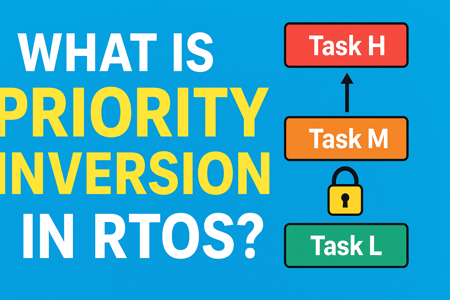
    Imagine you have three tasks in an RTOS:

    • Task H (High priority) → Needs a shared resource.
    • Task L (Low priority) → Currently holding the resource.
    • Task M (Medium priority) → Independent task that doesn’t need the resource.

    Here’s what happens:

    1. Task L locks the resource.
    2. Task H tries to access the same resource, but it is locked by Task L, so Task H must wait.
    3. Before Task L can finish, Task M starts running (since it has higher priority than Task L).
    4. Now, Task H (which is the most critical task) is waiting indirectly because Task M keeps running, delaying Task L from releasing the resource.

    This situation is called priority inversion.

    Why is Priority Inversion a Problem?

    • Missed deadlines: In real-time systems, tasks often have strict timing requirements.
    • Unpredictable behavior: The system no longer behaves as expected based on priority rules.
    • Reduced reliability: Critical applications (like automotive, aerospace, or medical devices) may fail due to delays.

    How Can Priority Inversion Be Mitigated?

    RTOS designers use specific techniques to solve priority inversion. The most common solutions are:

    1. Priority Inheritance Protocol

    When a low-priority task holds a resource needed by a high-priority task, the RTOS temporarily boosts the priority of the low-priority task to match the high-priority task.

    • This ensures the low-priority task quickly finishes and releases the resource.
    • After releasing, its priority is restored.

    2. Priority Ceiling Protocol

    In this method, each resource is assigned a priority ceiling (the highest priority of any task that may use it).

    • When a task locks the resource, it temporarily inherits the ceiling priority.
    • This prevents medium-priority tasks from preempting and causing delays.

    3. Careful Task Design

    • Keep critical sections (where resources are locked) as short as possible.
    • Avoid unnecessary resource sharing between high and low-priority tasks.
    • Use appropriate scheduling policies in the RTOS.

    Real-World Example of Priority Inversion

    NASA’s Mars Pathfinder mission famously experienced a system reset issue due to priority inversion. The problem was solved by enabling priority inheritance, which prevented further system failures.

    C++ Example using std::thread and std::mutex

    #include <iostream>
    #include <thread>
    #include <mutex>
    #include <chrono>
    
    std::mutex resource;
    
    void lowPriorityTask() {
        std::cout << "Low-priority task started and locking resource\n";
        resource.lock();  // Lock resource
        std::this_thread::sleep_for(std::chrono::seconds(5)); // Simulate long work
        resource.unlock();
        std::cout << "Low-priority task finished\n";
    }
    
    void mediumPriorityTask() {
        std::this_thread::sleep_for(std::chrono::milliseconds(500)); // Let low task start first
        std::cout << "Medium-priority task running\n";
        std::this_thread::sleep_for(std::chrono::seconds(2)); // Simulate work
        std::cout << "Medium-priority task finished\n";
    }
    
    void highPriorityTask() {
        std::this_thread::sleep_for(std::chrono::milliseconds(1000)); // Start after low task
        std::cout << "High-priority task trying to lock resource\n";
        resource.lock(); // Blocked here because low-priority holds it
        std::cout << "High-priority task got resource!\n";
        resource.unlock();
    }
    
    int main() {
        std::thread t1(lowPriorityTask);
        std::thread t2(mediumPriorityTask);
        std::thread t3(highPriorityTask);
    
        t1.join();
        t2.join();
        t3.join();
    
        return 0;
    }

    Output explanation:

    1. Low-priority task locks the resource.
    2. High-priority task wants it but is blocked.
    3. Medium-priority task runs and delays Low-priority task from finishing → High-priority task is indirectly delayed.

    This demonstrates priority inversion.

    C++ Simulation with Priority Inheritance (Conceptual)

    #include "FreeRTOS.h"
    #include "task.h"
    #include "semphr.h"
    
    SemaphoreHandle_t xMutex;
    
    void vLowPriorityTask(void *pvParameters) {
        xSemaphoreTake(xMutex, portMAX_DELAY);
        // Simulate work
        vTaskDelay(pdMS_TO_TICKS(5000));
        xSemaphoreGive(xMutex);
        vTaskDelete(NULL);
    }
    
    void vMediumPriorityTask(void *pvParameters) {
        vTaskDelay(pdMS_TO_TICKS(500));
        // Work that can preempt low priority
        vTaskDelay(pdMS_TO_TICKS(2000));
        vTaskDelete(NULL);
    }
    
    void vHighPriorityTask(void *pvParameters) {
        vTaskDelay(pdMS_TO_TICKS(1000));
        xSemaphoreTake(xMutex, portMAX_DELAY); // Will inherit low-priority task priority
        xSemaphoreGive(xMutex);
        vTaskDelete(NULL);
    }
    
    int main() {
        xMutex = xSemaphoreCreateMutex(); // FreeRTOS mutex with priority inheritance
    
        xTaskCreate(vLowPriorityTask, "Low", 1000, NULL, 1, NULL);
        xTaskCreate(vMediumPriorityTask, "Medium", 1000, NULL, 2, NULL);
        xTaskCreate(vHighPriorityTask, "High", 1000, NULL, 3, NULL);
    
        vTaskStartScheduler();
        return 0;
    }

    Here, FreeRTOS automatically boosts the low-priority task holding the mutex to the priority of the high-priority task if it tries to acquire it. This avoids priority inversion.

    Conclusion

    Priority inversion is an important concept every embedded systems or RTOS developer should understand. It happens when a high-priority task is blocked by a lower-priority task holding a resource. The good news is that RTOS kernels offer mechanisms like priority inheritance and priority ceiling protocols to solve this issue.

    By keeping critical sections short and designing tasks carefully, developers can prevent priority inversion and ensure their RTOS applications run smoothly and reliably.

    FAQ of Priority Inversion

    1.What is priority inversion in RTOS?

    Ans: Priority inversion occurs when a high-priority task is blocked because a low-priority task is holding a resource, while medium-priority tasks keep running.

    2.Why is priority inversion dangerous?

    Ans: It can cause missed deadlines, unpredictable system behavior, and failures in critical real-time systems like automotive, aerospace, and medical devices.

    3.How can priority inversion be prevented?

    Ans: Common solutions include priority inheritance protocol, priority ceiling protocol, and designing tasks so that resource locking is minimal.

    4.What is the difference between priority inheritance and priority ceiling?

    Ans:
    Priority inheritance temporarily raises the priority of the low-priority task holding a resource.
    Priority ceiling assigns the resource the highest priority of any task that might use it, preventing medium-priority interference.

    5.Can you give a real-world example of priority inversion?

    Ans: Yes, NASA’s Mars Pathfinder mission faced a system reset issue due to priority inversion, which was fixed using the priority inheritance mechanism.

    Priority Inversion Interview Questions

    Basic Level

    1. What is priority inversion in an RTOS?
    2. Explain with an example how a high-priority task can get blocked by a low-priority task.
    3. Why is priority inversion a problem in real-time systems?
    4. What is the difference between a high-priority and low-priority task in an RTOS context?

    Intermediate Level

    1. How does the priority inheritance protocol help in mitigating priority inversion?
    2. What is the priority ceiling protocol and how is it different from priority inheritance?
    3. Can priority inversion occur if there are no shared resources between tasks? Why or why not?
    4. How can careful task design help prevent priority inversion?

    Advanced Level

    1. Explain a real-world example where priority inversion caused a system failure.
    2. If a high-priority task is blocked due to priority inversion, how can you identify it using RTOS debugging tools?
    3. What are the trade-offs of implementing priority inheritance in an RTOS?
    4. How would you handle multiple resources being used by tasks of different priorities to avoid priority inversion?
    What is Priority Inversion
    What is Priority Inversion, and How Can it be Mitigated in an RTOS? | Master RTOS Interview Questions (2025)
  • Top Interview Questions on Interrupt Service Routine (ISR) | Master Embedded Interview Guide (2026)

    Interview Questions on Interrupt Service Routine : When preparing for embedded systems interviews, one of the most important topics is the Interrupt Service Routine (ISR). Recruiters often ask questions on ISR because it is a core concept in microcontrollers, operating systems, and real-time systems. In this guide, we’ll go through commonly asked ISR interview questions, explained in a simple way for beginners.

    What is an Interrupt Service Routine (ISR)?

    An Interrupt Service Routine (ISR) is a special block of code that executes when a hardware or software interrupt occurs. Instead of continuously checking a condition (polling), the system pauses its normal execution and jumps to the ISR to handle the event immediately.

    Example: When you press a button on a microcontroller, an interrupt occurs, and the ISR handles the button press.

    Interview Questions on Interrupt Service Routine
    Top Interview Questions on Interrupt Service Routine (ISR) Master Embedded Interview Guide (2025)

    Common Interview Questions on Interrupt Service Routine (ISR)

    1. What is an ISR in embedded systems?

    Answer: An ISR is a function that handles interrupts. It is triggered automatically when an interrupt occurs, allowing the CPU to respond quickly to external or internal events.

    2. What are the characteristics of an ISR?

    Answer:

    • Fast execution : Should be short and efficient.
    • No return values : ISR does not return values.
    • No blocking calls : Avoid using functions like delay() inside ISR.
    • Context saving : CPU saves the current state before jumping to ISR.

    3. Can an ISR call another function?

    Answer: Yes, but it should only call lightweight functions. Heavy operations inside ISR may slow down the system and block other interrupts.

    4. What are nested interrupts?

    Answer: Nested interrupts occur when a higher-priority interrupt occurs while another ISR is still running. In such cases, the CPU pauses the current ISR and executes the higher-priority one.

    5. Why should we keep ISRs short?

    Answer: Long ISRs delay the processing of other interrupts. In real-time systems, this can cause missed events and system instability.

    6. What is the difference between ISR and a normal function?

    Answer:

    • ISR executes automatically when an interrupt occurs, while a normal function is called manually.
    • ISR does not return values, while functions can.
    • ISR runs in a special CPU context and must be as short as possible.

    7. Can we use global variables inside ISR?

    Answer: Yes, but they must be declared as volatile so that the compiler does not optimize them. This ensures real-time updates between the ISR and the main program.

    8. What is interrupt latency?

    Answer: Interrupt latency is the time delay between an interrupt request and the start of ISR execution. Low latency is important for real-time systems.

    9. How do you handle multiple interrupts?

    Answer:

    • Assign priority levels to interrupts.
    • Use interrupt vectors to map different ISRs.
    • Ensure critical ISRs are shorter and higher priority.

    10. What are some best practices for writing ISRs?

    Answer:

    • Keep ISRs short and simple.
    • Use global variables carefully (mark them as volatile).
    • Avoid using printf, malloc, or delay inside ISR.
    • Handle only critical tasks inside ISR and defer others to the main loop or task scheduler.

    List of Interview Questions on Interrupt Service Routine (ISR)

    Basic Questions of Interrupt Service Routine interview questions

    1. What is an Interrupt Service Routine (ISR)?
    2. Why do we need ISR in embedded systems?
    3. What are the main features of an ISR?
    4. What is the difference between polling and ISR?
    5. What happens when an interrupt occurs?

    Intermediate Questions of ISR in embedded systems

    1. What are the rules for writing an ISR?
    2. Why should an ISR be short and fast?
    3. Can we use global variables inside ISR?
    4. What is the role of the volatile keyword in ISR?
    5. What is interrupt latency?
    6. Can an ISR return a value? Why or why not?
    7. What is the difference between ISR and a normal function?
    8. Can ISRs be nested? What are nested interrupts?
    9. How does the CPU know which ISR to execute?
    10. What is an interrupt vector table?

    Advanced Questions of common ISR interview questions

    1. How are multiple interrupts handled in a system?
    2. What are interrupt priorities?
    3. What is the difference between maskable and non-maskable interrupts?
    4. What are reentrant and non-reentrant ISRs?
    5. Can we use dynamic memory allocation (malloc/free) inside ISR?
    6. Why is it not recommended to use printf() inside ISR?
    7. What are some common mistakes while writing ISRs?
    8. How do you handle critical tasks inside ISR?
    9. What happens if an ISR takes too long to execute?
    10. How do modern microcontrollers reduce interrupt latency?

    Practical/Implementation Questions of interrupt handling in embedded systems

    1. How do you declare an ISR in C/C++?
    2. How do you enable and disable interrupts in a microcontroller?
    3. What is the difference between hardware and software interrupts?
    4. Can an ISR call another ISR?
    5. How do you share data between ISR and the main program?
    6. What are best practices for writing ISRs?
    7. What tools or debuggers can be used to test ISR execution?
    8. Can an ISR cause a system crash? How?
    9. How does an operating system handle interrupts differently from bare-metal programming?
    10. What is the difference between vectored and non-vectored interrupts?

    1.What is an Interrupt Service Routine (ISR)?

    Ans: An ISR is a special function that executes automatically when an interrupt occurs, allowing the CPU to handle events quickly without polling.

    2.Why do we use ISR in embedded systems?

    Ans: ISR reduces CPU load, improves response time, and makes systems more efficient by handling events only when they occur.

    3. Can an ISR return a value?

    Ans: No, ISRs cannot return values because they are executed by hardware/OS, not called like regular functions.

    4. Why should ISR be short and fast?

    Ans: Long ISRs block other interrupts and can cause system delays or missed events.

    5. Can we use global variables in ISR?

    Ans: Yes, but they should be declared as volatile to ensure real-time updates between ISR and the main program.

    6. What is interrupt latency?

    Ans: Interrupt latency is the time delay between an interrupt request and the start of ISR execution.

    7. Can we use printf or delay inside ISR?

    Ans: No, functions like printf, malloc, or delay should be avoided inside ISR as they are slow and may cause system instability.

    8. What is the difference between ISR and normal function?

    Ans:
    a) ISR executes automatically when an interrupt occurs, while a normal function is called explicitly.
    b) ISR does not return values, while functions can.
    c) ISR runs in a special CPU context.

    9. What are nested interrupts?

    Ans: Nested interrupts occur when a higher-priority interrupt interrupts the execution of a lower-priority ISR.

    10. What are best practices for writing ISRs?

    Ans:
    a) Keep ISRs short and efficient.
    b) Use volatile for shared variables.
    c) Avoid blocking functions.
    d) Handle only critical tasks inside ISR, defer the rest to main loop or task scheduler.
    Interrupt Service Routine
    Interrupt Service Routine (ISR) Definition, Examples, Best Practices Embedded Interview Guide (2025)
  • Embedded Software Engineers JOB USA | Associate / Experienced / Senior (2026)

    📍 Location: St. Louis, MO | 🕒 Posted 12 hours ago | 💼 On-site | 🏷️ Full-time

    Embedded Software Engineers JOB USA : We are hiring Embedded Software Engineers (Associate, Experienced, and Senior levels) to join our fast-growing team in the USA. This role involves designing, developing, testing, and maintaining real-time embedded software for cutting-edge defense, aerospace, and mission-critical applications.

    As part of our engineering team, you will contribute to the full software development life cycle (SDLC), including requirements analysis, architecture design, implementation, integration, and verification. You will work with modern technologies, Linux-based systems, C++ programming, and CI/CD pipelines, ensuring robust, secure, and high-performing embedded solutions.

    This position is ideal for engineers who are passionate about embedded systems, low-level programming, and hardware-software integration, and who are eager to grow in a collaborative and innovative environment.

    ✅ Key Highlights

    • Location: USA (St. Louis, MO & multiple options)
    • Work Type: Full-time, On-site
    • Levels: Associate, Experienced, Senior
    • Industry: Aerospace, Defense & Security

    🎯 Responsibilities

    • Develop, test, and maintain embedded software solutions.
    • Write efficient, secure, and optimized code in C++ and Linux environments.
    • Perform debugging, troubleshooting, and performance optimization.
    • Support integration of embedded software with specialized hardware.
    • Implement CI/CD pipelines and DevSecOps practices.
    • Participate in automated testing frameworks to ensure reliability.
    • Collaborate with cross-functional teams to deliver mission-critical systems.

    About the Role

    We are looking for talented Embedded Software Engineers (Associate, Experienced, and Senior levels) to join our Mission Systems Software team in Berkeley, MO. This role supports the Defense, Space & Security (BDS) division, working on cutting-edge projects that shape the future of aerospace and defense technology.

    You’ll be part of a collaborative engineering environment where you will design, build, and test real-time embedded software solutions. The work includes developing code, writing tests, performing simulations, and integrating solutions into complex systems. Our teams follow Agile practices, adopt CI/CD pipelines, and emphasize code quality, security, and automation.

    Key Responsibilities

    • Design, implement, test, and maintain embedded software for advanced systems.
    • Translate customer requirements into robust software solutions.
    • Write and integrate code for specialized embedded hardware.
    • Support hardware-software integration and ensure stable system performance.
    • Conduct unit, integration, and system-level testing, focusing on automation.
    • Debug and troubleshoot performance, memory, and timing issues.
    • Contribute to CI/CD pipelines, DevOps/DevSecOps workflows, and software process improvements.
    • Develop automated testing frameworks to validate functionality and performance.
    • Stay up to date with modern tools, frameworks, and industry standards.

    Basic Qualifications

    • 2+ years of professional software development experience.
    • Proficiency in C++ and/or Linux-based software development.
    • Hands-on experience with CI/CD pipelines.

    Preferred Qualifications

    • 3–5+ years of embedded software development experience.
    • Experience with DevOps/DevSecOps, automation, and secure coding practices.
    • Knowledge of debugging memory management and timing-related issues.
    • Familiarity with tools & frameworks such as:
      • Embedded Systems Software, Linux, Rust
      • Docker, Kubernetes, CMake, Git
      • CI/CD tools (GitLab, Jira, Ansible, Artifactory)
      • UML, SysML
      • Testing frameworks (Google Test, Cucumber, SonarQube, Coverity)

    Education & Experience

    • Associate Level (Level 2): Bachelor’s degree + 2+ years’ experience OR Master’s degree.
    • Experienced Level (Level 3): Bachelor’s degree + 5+ years OR Master’s + 3 years OR PhD.
    • Senior Level (Level 4): Bachelor’s degree + 9+ years OR Master’s + 7 years OR PhD + 4 years.
    • Fields: Computer Science, Engineering, Physics, Mathematics, or related disciplines.

    Salary Range

    • Associate (Level 2): $90,100 – $121,900
    • Experienced (Level 3): $110,500 – $149,500
    • Senior (Level 4): $132,600 – $179,400

    💰 Compensation will be based on experience, qualifications, and market alignment.

    Benefits

    • Competitive salary + performance-based incentives.
    • Health insurance, retirement plans, flexible spending & savings accounts.
    • Paid and unpaid leave programs.
    • Relocation assistance (based on eligibility).

    Additional Details

    • Work Type: 100% On-site | 1st Shift
    • Export Control: Must be a U.S. Person (Citizen, Green Card holder, Refugee, or Asylee).
    • Security Clearance: Must be able to obtain U.S. Security Clearance (Secret level required post-start).
    • Visa Sponsorship: Not available.
    • Drug-Free Workplace: Candidates must pass pre-employment screening.
    • Application Deadline: August 29, 2025

    Apply Link : Portal

    Why Join Us?

    You’ll be part of a mission-driven team working on next-generation defense and aerospace systems. We provide a supportive, inclusive workplace with significant opportunities for career advancement. If you’re passionate about embedded systems and want to make an impact in national defense and aerospace innovation, this is the role for you.

    [display-posts category=”jobs” order=”DESC”]

  • Interrupt Service Routine (ISR): Definition, Examples, Best Practices | Embedded Interview Guide

    Learn what an Interrupt Service Routine (ISR) is, how it works, with C examples, NVIC priorities, latency tips, Linux top/bottom halves, and common pitfalls.An Interrupt Service Routine (ISR) is a short, high-priority function that runs automatically when hardware or software triggers an interrupt. Its job is to respond fast, clear the source, and defer heavy work, so the system stays responsive and deterministic.

    What Is an Interrupt Service Routine?

    An Interrupt Service Routine (ISR) is a special function invoked by the CPU when an interrupt occurs—an asynchronous event like a timer tick, GPIO edge, UART byte received, or a fault condition. The CPU pauses the main thread, saves minimal context, jumps to the ISR address from the interrupt vector table, executes the routine, then returns to the pre-empted code.

    Why ISRs Exist

    • Responsiveness: Process time-critical events immediately.
    • Efficiency: Avoid constant polling loops.
    • Determinism: Bound the delay (latency) to meet real-time deadlines.

    Core Concepts You Should Know

    Interrupt Vector Table (IVT)

    A table of addresses that map each interrupt source to its ISR entry point. On ARM Cortex-M, the IVT (vector table) starts at a fixed address (often 0x00000000 or relocated) and includes reset and exception vectors.

    Maskable vs Non-Maskable

    • Maskable interrupts: Can be disabled (masked) by the CPU or software.
    • Non-Maskable Interrupt (NMI): Highest priority, cannot be masked, used for critical faults.

    Priority and Preemption (NVIC on ARM Cortex-M)

    The Nested Vectored Interrupt Controller (NVIC) assigns priorities. A higher-priority interrupt can preempt a lower one (nested interrupts). Proper priority design reduces worst-case latency for critical sources.

    Latency vs Response vs Service Time

    • Interrupt latency: Time from event to ISR start.
    • Response time: Latency plus any hardware pipeline delays.
    • Service time: Time spent inside the ISR.
      Goal: Minimize latency and service time to protect real-time behavior.

    Golden Rules for Writing ISRs

    1. Keep ISRs short and deterministic.
    2. Clear the interrupt source early (status/flag register).
    3. Never block: no delays, no busy-waits, avoid printf.
    4. Avoid dynamic allocation and heavy computations.
    5. Use volatile for shared variables modified in ISR and main/threads.
    6. Defer work to a main loop, RTOS task, or bottom half.
    7. Minimize critical sections (time with interrupts disabled).
    8. Make ISRs reentrant-safe or explicitly non-reentrant via hardware.
    9. Respect priority scheme; test worst-case nesting.
    10. Instrument and measure latency/jitter with GPIO toggles + scope/logic analyzer.

    Minimal C Example (Bare-Metal, Cortex-M Style)

    #include <stdint.h>
    #include "stm32f4xx.h" // device header (example)
    
    volatile uint8_t button_event = 0;
    
    void EXTI0_IRQHandler(void) {
        // Check pending flag for EXTI line 0
        if (EXTI->PR & EXTI_PR_PR0) {
            EXTI->PR = EXTI_PR_PR0;   // 1) Clear interrupt source early
            button_event = 1;         // 2) Set a small flag (volatile)
            // 3) Do not debounce here; defer heavy work to main/task
        }
    }
    
    int main(void) {
        // ... GPIO/EXTI/NVIC init: configure PA0 as input, EXTI0 on rising edge
        while (1) {
            if (button_event) {
                button_event = 0;
                // Handle button: debounce in main context or schedule a task
            }
            // other non-blocking work
        }
    }
    

    Why this is good: short ISR, clears the flag, uses a volatile flag, defers the work.

    With an RTOS (FreeRTOS) — Deferring Work Correctly

    // Assume a task waits on a notification or queue
    extern TaskHandle_t buttonTaskHandle;
    
    void EXTI0_IRQHandler(void) {
        BaseType_t xHigherPriorityTaskWoken = pdFALSE;
    
        if (EXTI->PR & EXTI_PR_PR0) {
            EXTI->PR = EXTI_PR_PR0;
            vTaskNotifyGiveFromISR(buttonTaskHandle, &xHigherPriorityTaskWoken);
            portYIELD_FROM_ISR(xHigherPriorityTaskWoken); // request context switch if needed
        }
    }
    

    Notes: Use the FromISR variants only. They are designed to be ISR-safe and avoid locking issues.

    Linux Driver Perspective : Top Half vs Bottom Half

    In the Linux kernel, the top half is the fast interrupt handler (ISR) that acknowledges the device and schedules a bottom half (e.g., tasklet or workqueue) to complete longer processing in process context.

    static irqreturn_t my_irq_handler(int irq, void *dev_id)
    {
        struct mydev *d = dev_id;
        u32 status = readl(d->mmio + STATUS);
    
        if (!(status & IRQ_OCCURRED))
            return IRQ_NONE;
    
        writel(status, d->mmio + STATUS); // Ack/clear quickly
        schedule_work(&d->work);          // Defer heavy work
        return IRQ_HANDLED;
    }
    

    This pattern mirrors the embedded “set a flag and get out quickly” philosophy.

    Designing Priorities and Handling Nested Interrupts

    • Put hard real-time sources (e.g., motor control, high-rate ADC, safety signals) at higher priority.
    • Keep their ISRs ultra-short; move computations to lower priority tasks.
    • Test nesting: Use synthetic interrupt storms to verify the system remains stable and meets deadlines.
    • Beware of priority inversion with shared resources — use lock-free queues or ISR-safe ring buffers.

    Reducing Interrupt Latency and Jitter

    • Disable interrupts for the shortest possible time.
    • Avoid large critical sections (__disable_irq() / __enable_irq() sparingly).
    • Use branch-free, cache-friendly code in hot paths.
    • Ensure vector table is in fast memory (when relocatable).
    • Tune compiler optimization for ISR sections (inline, -O2/-O3 judiciously).
    • Prefer DMA + ISR for completion events instead of byte-wise ISRs.

    Common Mistakes (and Fixes)

    • Forgetting volatile: Variables changed in ISR must be volatile to avoid compiler reordering/optimization issues.
    • Not clearing the interrupt flag: Causes immediate retrigger or lockup.
    • Work inside ISR too heavy: Leads to missed deadlines; always defer.
    • Calling non-reentrant APIs (like printf, malloc) in ISR: avoid or provide ISR-safe alternatives.
    • Priority misconfiguration: A low-priority critical ISR getting delayed.
    • Debouncing in ISR: Use timers or software debouncing in main/task context instead.

    Testing & Debugging ISRs

    • Oscilloscope method: Toggle a GPIO at ISR entry/exit to measure latency and service time.
    • Logic analyzer: Correlate multiple events (e.g., RX line vs ISR start).
    • Fault handlers: Implement HardFault/NMI handlers with minimal logging hooks.
    • Stress tests: Burst interrupts, nested paths, and DMA completion storms.
    • Static analysis: Check for race conditions, missing volatile, and reentrancy issues.

    Quick ISR Checklist (Pin or print)

    • ISR is short and clears the source early
    • Uses volatile for shared flags/counters
    • No blocking calls, no dynamic allocation
    • Work deferred to main/task/bottom half
    • Priorities documented and tested for nesting
    • Latency/jitter measured with GPIO or tracing
    • Minimal time with interrupts disabled
    • Safe access to shared peripherals/buffers

    Top Interview Questions on Interrupt Service Routine (ISR)

    Now that you have a comprehensive understanding of Interrupt Service Routine (ISR) , you are well-equipped to confidently solve related problems and excel in interviews in one shot. Focus on mastering questions such as:

    1. What is an Interrupt Service Routine (ISR) in embedded systems, and why is it important?
    2. Explain how an ISR differs from a normal function call in embedded programming.
    3. What are the key steps involved in writing an effective ISR?
    4. How do you ensure minimal latency in an ISR execution?
    5. What are the best practices for ISR design in embedded systems?
    6. How is ISR priority determined in a microcontroller or processor?
    7. Explain the role of interrupt vectors in ISR execution.
    8. How do you handle nested interrupts in an embedded application?
    9. What are the common mistakes to avoid when writing an ISR?
    10. How do ISRs interact with the main program or RTOS tasks?
    11. Explain the impact of interrupt latency on real-time performance.
    12. How do you debug and test ISR functions in embedded systems?
    13. What tools and techniques are commonly used for ISR profiling?
    14. How can ISR execution affect system stability and reliability?
    15. Share an example where ISR optimization significantly improved performance in your embedded project.

    FAQ: Interrupt Service Routine

    Q1. What exactly is an Interrupt Service Routine?
    An ISR is a high-priority function that automatically runs when an interrupt occurs, handles the event quickly, and returns control to normal code.

    Q2. What should never be inside an ISR?
    Blocking calls, long loops, printf, dynamic memory allocation, or any heavy computation. Defer to a task/bottom half.

    Q3. How do I share data between ISR and main code safely?
    Use volatile for simple flags/counters. For larger data, use lock-free ring buffers or RTOS queues with FromISR APIs.

    Q4. What is interrupt latency and how do I reduce it?
    Latency is the delay from the event to ISR start. Reduce by shortening disabled-interrupt regions, optimizing priorities, and keeping ISRs minimal.

    Q5. Are nested interrupts good or bad?
    They’re essential for critical events but must be used carefully. Keep higher-priority ISRs ultra-short and validate worst-case timing.

    Conclusion

    An Interrupt Service Routine is the backbone of a responsive embedded and real-time system. Design for speed, simplicity, and determinism: acknowledge the event, clear the source, and defer the heavy work. With disciplined priorities, careful sharing of data, and solid testing, your ISRs will meet deadlines and keep the whole system stable.

    Interrupt Service Routine
    Interrupt Service Routine (ISR) Definition, Examples, Best Practices Embedded Interview Guide (2025)
  • Senior Embedded Software Engineer Jobs – Microcontrollers | General Motors Careers in Michigan (Hybrid)

    Apply for the Senior Embedded Software Engineer – Microcontrollers role at General Motors (GM) in Milford & Pontiac, Michigan. Work on AUTOSAR MCAL, RTOS, Embedded C, and microcontroller software development in a hybrid position. Explore GM careers with competitive benefits, relocation support, and growth opportunities.

    Location: Milford, Michigan / Pontiac, Michigan
    Schedule: Full-Time | Hybrid Work Model
    Job ID: JR-202511530
    Posted On: August 13, 2025

    About the Role

    General Motors is seeking a Senior Embedded Software Engineer – Microcontrollers to join our Hardware Input/Output (HWIO) Engineering Team within the Mechatronics Software Platform organization. This role plays a critical part in GM’s Software Defined Vehicle (SDV) strategy, focusing on low-level embedded software development that is portable, scalable, and built for next-generation automotive applications.

    As a Senior Embedded Software Developer, you will design, implement, and test hardware I/O software for microcontrollers while collaborating with cross-functional teams to ensure robust, secure, and reliable solutions that align with GM’s coding standards.

    Key Responsibilities

    • Develop and test low-level embedded software for microcontroller features including:
      • RTOS, Memory, Fault Detection, Power Management, DMA, PWM, LIN, Analog & Discrete I/O
    • Use AUTOSAR MCAL configuration tools or hand-code solutions in Embedded C
    • Define and execute testing strategies to validate compliance with system requirements
    • Perform independent code reviews and provide constructive feedback
    • Collaborate with hardware, calibration, and requirements engineering teams
    • Troubleshoot and resolve complex technical issues using strong analytical skills
    • Document software design, test cases, and results to meet industry standards

    Required Qualifications

    • Bachelor’s degree in Computer Engineering, Computer Science, Electrical Engineering, or related field
    • 5+ years of embedded software development experience with Embedded C
    • Expertise in AUTOSAR MCAL configuration and Complex Driver Development
    • Hands-on experience with ARM, PowerPC, and Renesas microcontrollers
    • Proficiency in RTOS development for multi-core systems
    • Strong knowledge of schematics and electrical circuits
    • Experience with root cause analysis for integrated software systems
    • Familiarity with debugging tools such as Lauterbach, ETAS INCA, CANalyzer, and lab equipment like oscilloscopes
    • Strong oral, written, and interpersonal communication skills

    Preferred Qualifications

    • Master’s degree in Computer Engineering, Computer Science, or related field
    • 8+ years of embedded C development experience
    • Specialized experience with:
      • ARM Cortex-R52 Core
      • ARM Cortex-M7 Core
      • NXP S32Kxx microcontrollers
      • Renesas RH850 microcontrollers
    • Knowledge of vehicle electrical systems

    Why Join GM?

    At General Motors, our vision is a world with Zero Crashes, Zero Emissions, and Zero Congestion. We embrace innovation, collaboration, and a culture where every employee feels valued and included.

    Benefits & Perks

    GM provides a comprehensive Total Rewards Package including:

    • Medical, dental, and vision coverage
    • Health Savings Account & Flexible Spending Accounts
    • 401(k) retirement savings plan
    • Paid vacation, holidays, and life insurance
    • Tuition assistance programs
    • GM vehicle discounts
    • Employee assistance program
    • Relocation benefits (if eligible)

    Diversity & Inclusion

    GM is committed to fostering a diverse and inclusive workplace. All employment decisions are made without discrimination based on race, gender, age, disability, veteran status, sexual orientation, or other protected categories.

    Apply Today

    If you’re passionate about embedded systems, microcontrollers, AUTOSAR MCAL, and automotive innovation, we encourage you to apply for the Senior Embedded Software Engineer – Microcontrollers role in Milford, Michigan or Pontiac, Michigan.

    Link to Apply : Career Portal

    Be part of a team that is shaping the future of the automotive industry through advanced embedded software engineering

  • Memory Protection Unit (MPU): Features, Importance & Applications | Master Embedded Interview 2026

    Learn everything about the Memory Protection Unit (MPU), its key features, working, advantages, and applications in embedded systems. Discover how a memory protection unit improves security, stability, fault isolation, and safety in microcontrollers and RTOS-based designs.

    Introduction

    In modern embedded systems and microcontrollers, ensuring safe and reliable execution of code is a critical requirement. This is where the Memory Protection Unit (MPU) plays a vital role. The MPU is a hardware feature that provides memory access control, enhances system security, and prevents unintended memory corruption. For developers working with real-time operating systems (RTOS) or safety-critical applications, understanding the memory protection unit is essential.

    What is a Memory Protection Unit (MPU)?

    A Memory Protection Unit is a hardware component integrated into many microcontrollers and processors. Its primary job is to control how different parts of memory (RAM, Flash, peripherals, etc.) can be accessed by applications or processes. Unlike a full Memory Management Unit (MMU) used in complex processors, the MPU is lightweight and designed for resource-constrained embedded devices.

    With an MPU, developers can define memory regions, assign access permissions, and protect critical data or code from being accidentally modified.

    Key Features of a Memory Protection Unit

    1. Region-Based Protection
      • The MPU allows memory to be divided into regions. Each region can have specific permissions such as read-only, write-only, or read/write access.
    2. Privilege Levels
      • It supports different privilege levels (e.g., user mode and privileged mode), preventing untrusted code from modifying system resources.
    3. Fault Handling
      • If a program tries to access restricted memory, the MPU triggers a fault, ensuring safe execution.
    4. Lightweight Design
      • The memory protection unit does not perform address translation like an MMU, which makes it suitable for microcontrollers with limited resources.
    5. Support for Real-Time Systems
      • The MPU enables better isolation in RTOS-based applications, helping achieve safety certifications like ISO 26262 (automotive) and IEC 61508 (industrial).

    Why Do We Need a Memory Protection Unit?

    • System Stability: Prevents one faulty task from corrupting another task’s memory.
    • Security: Protects sensitive data and system-level code from unauthorized access.
    • Debugging Support: Helps developers detect invalid memory accesses quickly.
    • Safety Compliance: Essential for industries like automotive, aerospace, and medical devices.

    Difference Between MPU and MMU

    FeatureMPU (Memory Protection Unit)MMU (Memory Management Unit)
    FunctionProvides access control and protectionProvides virtual memory and paging
    ComplexityLightweight, simpleMore complex
    TargetMicrocontrollers, embedded systemsHigh-end processors, desktops, servers
    Address TranslationNot supportedFully supported

    Address Translation in an Operating System (OS) is the process of converting a logical (virtual) address generated by a program into a physical address in main memory (RAM).

    Think of it like this :
    a) Program speaks virtual addresses
    b) Hardware (RAM) understands physical addresses
    c) OS + hardware act as the translator

    Why Address Translation is needed

    1. Programs don’t know actual RAM locations
    2. Multiple programs run at the same time
    3. Memory protection & isolation
    4. Efficient memory usage (virtual memory)

    So every process thinks:

    “I start at address 0”

    …but in reality, they are placed at different physical locations.

    Types of Addresses

    1. Logical (Virtual) Address

    • Generated by the CPU
    • Used by programs
    • Example: 0x0040

    2. Physical Address

    • Actual location in RAM
    • Used by memory hardware
    • Example: 0xA040

    How Address Translation Works

    Simple View

    Logical Address  ──► Address Translation ──► Physical Address
    

    This translation is mainly done by MMU (Memory Management Unit).

    Common Address Translation Techniques

    Base and Limit Register (Simple OS)

    • Base Register → starting physical address of process
    • Limit Register → size of process memory

    Formula:

    Physical Address = Base + Logical Address
    

    Example:

    Base = 1000
    Logical Address = 200
    Physical Address = 1200
    

    If logical address ≥ limit → ❌ invalid (memory protection)

    Paging

    Memory is divided into:

    • Pages (virtual memory)
    • Frames (physical memory)

    Translation steps:

    1. Logical address → (Page Number + Offset)
    2. Page Number → Frame Number (via Page Table)
    3. Physical address → (Frame Number + Offset)
    Logical Address
       ├── Page No
       └── Offset
    
    Page Table
       Page No ──► Frame No
    
    Physical Address
       ├── Frame No
       └── Offset
    

    ✔ No external fragmentation
    ✔ Efficient memory usage

    Segmentation

    Memory is divided into segments:

    • Code
    • Data
    • Stack

    Each segment has:

    • Base
    • Limit

    Physical Address = Segment Base + Offset

    ✔ Matches program structure
    ❌ External fragmentation

    Paging + Segmentation (Advanced OS)

    Used in modern systems for:

    • Better protection
    • Better flexibility

    Role of MMU

    • Performs address translation
    • Checks access permissions
    • Uses TLB (Translation Lookaside Buffer) for fast lookup

    Real-Life Analogy

    • Logical address → House number
    • Physical address → GPS coordinates
    • OS/MMU → Google Maps translating it

    Applications of a Memory Protection Unit

    • Automotive ECUs (Engine Control Units)
    • Medical devices with safety requirements
    • Industrial automation systems
    • Consumer electronics (IoT devices, wearables)
    • Defense and aerospace systems

    Conclusion

    The Memory Protection Unit (MPU) is a powerful hardware feature for embedded systems, ensuring secure, stable, and reliable program execution. By restricting unauthorized access, isolating memory regions, and enhancing system safety, the MPU has become a standard component in microcontroller design.

    For developers aiming to build secure and safety-critical embedded applications, mastering the memory protection unit is not optional—it’s a necessity.

    Advantages of Memory Protection Unit (MPU)

    1. System Stability
      • The memory protection unit prevents faulty tasks from corrupting other tasks’ memory, ensuring stable system performance.
    2. Improved Security
      • It restricts unauthorized access to sensitive data and code, making embedded devices more secure.
    3. Fault Isolation
      • MPU detects invalid memory accesses quickly and generates a fault, helping developers identify and fix issues.
    4. Low Resource Overhead
      • Unlike a memory management unit (MMU), the memory protection unit is lightweight, making it ideal for resource-constrained microcontrollers.
    5. Safety Compliance
      • Essential for achieving industry safety certifications such as ISO 26262 (automotive) and IEC 61508 (industrial).
    6. Support for RTOS
      • Provides task isolation in real-time operating systems, improving reliability of multitasking environments.

    Disadvantages of Memory Protection Unit (MPU)

    1. Limited Flexibility
      • The memory protection unit cannot perform address translation or virtual memory, unlike MMUs.
    2. Region Restrictions
      • MPUs usually support only a fixed number of memory regions, which may not be enough for complex applications.
    3. Manual Configuration
      • Developers must carefully configure regions and permissions; incorrect setup can cause frequent memory faults.
    4. Not Suitable for High-End Systems
      • While MPU is great for microcontrollers, it cannot match the advanced features of MMUs in high-end processors.
    5. Debugging Overhead
      • Frequent memory faults due to strict protection may slow down development if not handled properly.

    Interview Questions on Memory Protection Unit (MPU)

    Basic Level Questions

    1. What is a Memory Protection Unit (MPU)?
    2. How does a memory protection unit differ from a memory management unit (MMU)?
    3. Why do microcontrollers use an MPU instead of an MMU?
    4. What are the main features of a memory protection unit?
    5. Can you explain how MPU helps in debugging embedded systems?
    6. What happens when a task tries to access a restricted memory region in MPU?

    Intermediate Level Questions

    1. How does the MPU handle privilege levels in embedded systems?
    2. How many memory regions can typically be defined in an ARM Cortex-M MPU?
    3. Explain how an MPU improves system stability in RTOS-based applications.
    4. What is the role of MPU in achieving safety certifications like ISO 26262?
    5. How does the MPU support read, write, and execute permissions for memory?
    6. What kind of fault is generated if unauthorized memory access occurs?

    Advanced Level Questions

    1. Compare MPU-based protection with software-based memory protection.
    2. How would you configure an MPU in ARM Cortex-M architecture?
    3. What are the challenges of using MPU in complex embedded systems?
    4. How does MPU improve security in IoT devices?
    5. In what scenarios would you choose MPU over MMU for system design?
    6. How does the MPU interact with exception handling in microcontrollers?
    7. Can MPU be used to protect peripheral registers as well as RAM/Flash memory?
    8. Give a real-world example where MPU played a critical role in system reliability.
    Memory Protection Unit (MPU)
    Memory Protection Unit (MPU) Features, Importance & Applications Master Embedded Interview 2025