Author: admin

  • Integrating DHT11 Sensor Driver into Yocto Image for BeagleBone | Master Step-by-Step LDD Guide

    DHT11 Sensor Driver into Yocto : When I first got my BeagleBone board, I was super excited. I wanted to connect real-world sensors and see live data flowing into my board. One of the simplest yet powerful sensors I picked was the DHT11, a low-cost digital temperature and humidity sensor.

    At first glance, I thought: “It should be as easy as connecting a wire and running a Python script, right?” But then came the challenge — I wanted to integrate it properly at the kernel driver level and make it part of my Yocto-built image, so that every time I flashed my SD card, my BeagleBone would already have the driver and I could directly fetch temperature readings.

    If you’ve ever felt this curiosity, this guide is for you. Let’s go step by step.

    Manual Way: Adding DHT11 Sensor Driver into Yocto for BeagleBone

    Why DHT11 Sensor Driver into Yocto ?

    • Consistency: Every image build includes your driver — no need to manually insert modules each time.
    • Customization: You can control how the driver behaves and integrate it with other services.
    • Scalability: If tomorrow you move to another sensor or a production board, your Yocto setup scales with you.

    Step 1: Set Up Yocto Project Environment

    1. Download Poky and layers git clone git://git.yoctoproject.org/poky.git cd poky git checkout <yocto-version> # e.g., dunfell, honister
    2. Add necessary layers for BeagleBone git clone git://git.yoctoproject.org/meta-ti.git git clone git://git.yoctoproject.org/meta-openembedded.git
    3. Create a build directory source oe-init-build-env build
    4. Set your machine in conf/local.conf MACHINE ?= "beaglebone"

    Step 2: Understand Your DHT11 Sensor

    • DHT11 uses 1-wire digital communication.
    • Pins:
      • VCC: 3.3V or 5V
      • GND: Ground
      • DATA: Connected to a GPIO pin on BeagleBone
    • The driver needs to read the digital pulses and convert them to temperature and humidity.

    Step 3: Create a Custom Layer

    1. Create a new layer for your driver: bitbake-layers create-layer meta-dht11
    2. Add this layer to your build: bitbake-layers add-layer ../meta-dht11

    Step 4: Write the Kernel Driver

    4.1: Create Driver Skeleton

    • Go to your layer: meta-dht11/recipes-kernel/dht11/
    • Create dht11.c:
    #include <linux/module.h>
    #include <linux/kernel.h>
    #include <linux/init.h>
    #include <linux/gpio.h>
    #include <linux/delay.h>
    #include <linux/fs.h>
    #include <linux/uaccess.h>
    
    #define DHT11_PIN 60  // Example: GPIO1_28 on BeagleBone
    
    static int major;
    static char temp_str[16];
    
    static int dht11_open(struct inode *inode, struct file *file) {
        return 0;
    }
    
    static int dht11_release(struct inode *inode, struct file *file) {
        return 0;
    }
    
    static ssize_t dht11_read(struct file *file, char __user *buf, size_t len, loff_t *offset) {
        int temperature = 25; // Mock value (we’ll implement real reading later)
        snprintf(temp_str, sizeof(temp_str), "%d\n", temperature);
        if (copy_to_user(buf, temp_str, strlen(temp_str))) {
            return -EFAULT;
        }
        return strlen(temp_str);
    }
    
    static struct file_operations fops = {
        .owner = THIS_MODULE,
        .open = dht11_open,
        .release = dht11_release,
        .read = dht11_read,
    };
    
    static int __init dht11_init(void) {
        major = register_chrdev(0, "dht11", &fops);
        printk(KERN_INFO "DHT11 driver loaded. Major=%d\n", major);
        return 0;
    }
    
    static void __exit dht11_exit(void) {
        unregister_chrdev(major, "dht11");
        printk(KERN_INFO "DHT11 driver unloaded\n");
    }
    
    module_init(dht11_init);
    module_exit(dht11_exit);
    
    MODULE_LICENSE("GPL");
    MODULE_AUTHOR("Nish");
    MODULE_DESCRIPTION("DHT11 temperature driver for BeagleBone");
    

    4.2: Create the Recipe (.bb file)

    • File: meta-dht11/recipes-kernel/dht11/dht11.bb
    DESCRIPTION = "DHT11 temperature driver"
    LICENSE = "GPLv2"
    SRC_URI = "file://dht11.c"
    
    S = "${WORKDIR}"
    
    do_compile() {
        ${CC} -Wall -O2 -c ${WORKDIR}/dht11.c -o ${WORKDIR}/dht11.o
        ${CC} -Wall -O2 -shared -o ${WORKDIR}/dht11.ko ${WORKDIR}/dht11.o
    }
    
    do_install() {
        install -d ${D}${sysconfdir}/modules
        install -m 0644 ${WORKDIR}/dht11.ko ${D}${sysconfdir}/modules/
    }
    

    Step 5: Build and Add Driver to Image

    1. Build the driver: bitbake dht11
    2. Include it in your image (local.conf): IMAGE_INSTALL_append = " dht11"
    3. Rebuild your image: bitbake core-image-minimal

    Step 6: Boot BeagleBone and Test

    1. Flash .wic image to SD card.
    2. Boot BeagleBone.
    3. Load driver: insmod /etc/modules/dht11.ko
    4. Check temperature: cat /dev/dht11

    Step 7: Implement Actual DHT11 Reading

    • Replace mock temperature with real GPIO reading.
    • Use bit-banging with gpio_get_value() and precise timing with udelay().

    Tips

    • Make sure GPIO pin numbers match your BeagleBone header.
    • For production, consider interrupt-based reading for better accuracy.
    • Use dmesg to debug kernel messages.

    Auto Temperature Reading Without Manual Module Loading

    Step 1: Setup Yocto Kirkstone Environment

    1. Clone Poky (Kirkstone branch):
    git clone -b kirkstone git://git.yoctoproject.org/poky.git
    cd poky
    
    1. Clone meta layers:
    git clone -b kirkstone git://git.yoctoproject.org/meta-openembedded.git
    git clone -b kirkstone git://git.yoctoproject.org/meta-ti.git
    
    1. Initialize the build environment:
    source oe-init-build-env
    
    1. Set your target machine in conf/local.conf:
    MACHINE ?= "beaglebone"
    

    Step 2: Create a Custom Layer for DHT11

    1. Create layer:
    bitbake-layers create-layer meta-dht11
    
    1. Add it to your build:
    bitbake-layers add-layer ../meta-dht11
    

    Step 3: Write the DHT11 Driver

    1. Go to your layer folder:
      meta-dht11/recipes-kernel/dht11/
    2. Create dht11.c:
    #include <linux/module.h>
    #include <linux/kernel.h>
    #include <linux/init.h>
    #include <linux/gpio.h>
    #include <linux/delay.h>
    #include <linux/fs.h>
    #include <linux/uaccess.h>
    
    #define DHT11_PIN 60  // Adjust according to BeagleBone header
    
    static int major;
    static char buf[32];
    
    static int dht11_open(struct inode *inode, struct file *file) { return 0; }
    static int dht11_release(struct inode *inode, struct file *file) { return 0; }
    
    static int read_dht11(int *temperature, int *humidity) {
        int bits[40] = {0}, i, j=0, data[5] = {0};
    
        // Send start signal
        gpio_direction_output(DHT11_PIN, 0);
        mdelay(20);
        gpio_direction_input(DHT11_PIN);
        udelay(30);
    
        // Wait for response
        while(gpio_get_value(DHT11_PIN) == 1);
        while(gpio_get_value(DHT11_PIN) == 0);
        while(gpio_get_value(DHT11_PIN) == 1);
    
        // Read 40 bits
        for(i=0;i<40;i++){
            while(gpio_get_value(DHT11_PIN) == 0);
            j=0;
            while(gpio_get_value(DHT11_PIN) == 1){ udelay(1); j++; }
            bits[i] = (j > 40) ? 1 : 0;
        }
    
        // Convert bits to bytes
        for(i=0;i<5;i++){
            data[i]=0;
            for(j=0;j<8;j++){
                data[i]<<=1;
                data[i] |= bits[i*8+j];
            }
        }
    
        if(data[4] != ((data[0]+data[1]+data[2]+data[3]) & 0xFF)) return -1;
    
        *humidity = data[0];
        *temperature = data[2];
        return 0;
    }
    
    static ssize_t dht11_read(struct file *file, char __user *user_buf, size_t len, loff_t *offset){
        int temp=0, hum=0;
        if(read_dht11(&temp,&hum)!=0) return -EIO;
        snprintf(buf,sizeof(buf),"Temp:%dC Hum:%d%%\n",temp,hum);
        if(copy_to_user(user_buf,buf,strlen(buf))) return -EFAULT;
        return strlen(buf);
    }
    
    static struct file_operations fops = {
        .owner=THIS_MODULE,
        .open=dht11_open,
        .release=dht11_release,
        .read=dht11_read,
    };
    
    static int __init dht11_init(void){
        major = register_chrdev(0,"dht11",&fops);
        printk(KERN_INFO "DHT11 driver loaded. Major=%d\n",major);
        return 0;
    }
    
    static void __exit dht11_exit(void){
        unregister_chrdev(major,"dht11");
        printk(KERN_INFO "DHT11 driver unloaded\n");
    }
    
    module_init(dht11_init);
    module_exit(dht11_exit);
    
    MODULE_LICENSE("GPL");
    MODULE_AUTHOR("Nish");
    MODULE_DESCRIPTION("DHT11 driver for BeagleBone with real readings");
    

    Step 4: Create the BitBake Recipe

    Create dht11.bb in the same folder:

    DESCRIPTION = "DHT11 Temperature & Humidity Kernel Driver"
    LICENSE = "GPLv2"
    SRC_URI = "file://dht11.c"
    
    S = "${WORKDIR}"
    
    do_compile() {
        ${CC} -Wall -O2 -c ${WORKDIR}/dht11.c -o ${WORKDIR}/dht11.o
        ${CC} -Wall -O2 -shared -o ${WORKDIR}/dht11.ko ${WORKDIR}/dht11.o
    }
    
    do_install() {
        install -d ${D}${nonarch_libdir}/modules
        install -m 0644 ${WORKDIR}/dht11.ko ${D}${nonarch_libdir}/modules/
        # Auto-load at boot
        install -d ${D}/etc/modules-load.d
        echo "dht11" > ${D}/etc/modules-load.d/dht11.conf
    }
    

    Step 5: Include Driver in Yocto Image

    Edit conf/local.conf and add:

    IMAGE_INSTALL_append = " dht11"
    

    Step 6: Build the Image

    bitbake core-image-minimal
    

    After completion, your image already includes the DHT11 driver and will auto-load at boot.

    Step 7: Flash SD Card and Test

    1. Flash .wic image to SD card.
    2. Boot BeagleBone.
    3. Check temperature and humidity:
    cat /dev/dht11
    # Example output: Temp:27C Hum:55%
    

    ✅ You don’t need to insmod anymore. The driver is now part of the image.

    Integrating DHT11 Sensor Driver into Yocto Image for BeagleBone
    Integrating DHT11 Sensor Driver into Yocto Image for BeagleBone Master Step-by-Step Guide (2025)
  • Master Yocto Interview Questions | SET #1

    Master the most important Yocto interview questions for 2025. Prepare effectively for embedded software engineer roles with beginner to advanced level questions. The Yocto Project has become a standard in the embedded Linux world. Companies across automotive, industrial, IoT, and consumer electronics rely on Yocto to build custom Linux distributions. If you are preparing for an interview as an Embedded Software Engineer, having a strong grasp of Yocto is crucial.

    This article covers carefully structured Yocto interview questions ranging from basic concepts to real-world problem-solving. Whether you are a fresher, intermediate developer, or senior engineer, this guide will help you prepare confidently.

    I still remember the first time I heard the word Yocto. It was during a late-night debugging session on an automotive project. Our team had been struggling to bring up a custom Linux distribution on new hardware. Someone casually mentioned, “Why don’t we just use Yocto for this?” At that moment, Yocto felt like a mysterious black box—powerful, but intimidating.

    Weeks later, after diving into documentation, recipes, and layers, I realized that Yocto wasn’t just another build system. It was the toolchain that empowered companies across automotive, IoT, industrial, and consumer electronics to build Linux their way. And the more I learned, the more I noticed a pattern—every serious embedded Linux interview I attended started testing my Yocto knowledge.

    One interviewer leaned forward and asked me:
    “If you had to add a new package into your image, what steps would you follow in Yocto?”

    Another one challenged me with:
    “How would you debug a build failure in BitBake, especially when dependencies aren’t obvious?”

    At first, these questions felt overwhelming. But over time, I saw the logic: Yocto interviews are not about memorizing commands—they are about proving you can handle the real challenges teams face every day.

    That’s why I decided to put together this collection of Yocto interview questions for 2025. It’s not just theory—it’s structured from the ground up, the same way you grow in your career:

    • Basics for freshers to break the ice
    • Intermediate for developers who’ve shipped at least one Linux product
    • Advanced, real-world problem-solving for senior engineers who need to think beyond commands

    By the end of this guide, you won’t just know the answers—you’ll understand the why behind them. And that’s exactly what interviewers are looking for.

    Yocto Interview Questions

    Basic Yocto Interview Questions

    Ans: The Yocto Project is an open-source project that helps developers build custom Linux operating systems for embedded devices. Instead of downloading a ready-made Linux distribution like Ubuntu or Debian, Yocto gives you the tools to create your own Linux system that is lightweight, flexible, and tailored exactly to your hardware and project needs.

    In simple words, think of Yocto as a kitchen for Linux:

    • You don’t get a pre-cooked meal (like Ubuntu).
    • Instead, you get all the ingredients, recipes, and tools to cook your own dish (a custom Linux).
    • This means you can decide what to include (drivers, libraries, applications) and what to leave out.

    It is widely used in embedded systems (like automotive systems, IoT devices, routers, and medical equipment) because:

    1. Customization – Embedded devices often have limited memory, storage, and processing power. Yocto lets you strip away unnecessary features and keep only what’s needed.
    2. Cross-Compilation – It can build Linux for different processor architectures (ARM, x86, PowerPC, etc.), which is common in embedded systems.
    3. Consistency – It ensures the same build process can be repeated, making development and debugging easier across teams.
    4. Long-Term Support – Embedded devices usually run for years, so having a reliable and maintainable Linux system is critical.

    Imagine you are building a smart thermostat for your home. This thermostat needs to:

    • Read the room temperature from a sensor
    • Show the temperature on a small display
    • Connect to Wi-Fi and send data to a mobile app

    Now, you don’t need a full Linux desktop with web browsers, office apps, or games—most of that would just waste space and memory.

    Here’s where Yocto comes in:

    1. You use Yocto to build a Linux system specifically for your thermostat.
    2. You include only the necessary pieces: drivers for the temperature sensor, display support, Wi-Fi libraries, and your app.
    3. You leave out everything else, making the system lightweight and fast.
    4. Yocto also lets you cross-compile, meaning you can build this Linux system on your PC and then run it on the thermostat’s ARM processor.
    5. Later, if you want to update the thermostat’s software, you can rebuild it the same way, keeping everything consistent.

    So, in simple terms, Yocto is like custom-building the engine and body of a car instead of buying a full car you don’t need—you get exactly what your device needs to run perfectly.

    Ans: When it comes to building Linux for embedded systems, there are several tools you can use, like Yocto and Buildroot. Both help you create a custom Linux system for your device, but they work differently and have different strengths.

    1. Purpose and Scope
      • Yocto is more like a complete toolkit for building a full Linux distribution. It’s not just about compiling the kernel; it helps you create everything — the root filesystem, libraries, applications, and even your own custom packages.
      • Buildroot is simpler. It’s mostly focused on generating a minimal root filesystem and cross-compiling packages for your target device. It’s faster and easier to get started with but doesn’t offer as much flexibility for complex systems.
    2. Flexibility
      • Yocto is extremely flexible. You can fine-tune almost every part of your system, like which version of libraries to use, how packages are built, and even create your own custom layers.
      • Buildroot is more limited in flexibility. It’s great if you need a small, simple system quickly, but for very complex projects, you might feel restricted.
    3. Complexity and Learning Curve
      • Yocto has a steeper learning curve. It uses concepts like recipes, layers, and BitBake commands, which can seem overwhelming at first. But once you understand it, it’s very powerful for managing large projects.
      • Buildroot is beginner-friendly and easier to understand. You can get a working Linux system in a shorter time without learning too many advanced concepts.
    4. Reproducibility and Maintenance
      • Yocto shines in creating reproducible builds. If you rebuild your project on a different machine, you’re likely to get the exact same result. It’s designed for long-term maintenance and large projects.
      • Buildroot is okay for reproducibility but not as robust as Yocto for maintaining complex or large-scale systems.
    5. Community and Ecosystem
      • Yocto has a large ecosystem and is widely used in industries like automotive, telecom, and IoT. It supports a wide range of hardware and has extensive documentation.
      • Buildroot is smaller and simpler, mainly used for smaller embedded projects.

    In short:

    Use Yocto if you need a fully customized, maintainable Linux system for a complex embedded device. Use Buildroot if you want something quick, small, and easy.

    Ans: When working with the Yocto Project, you’ll often hear about something called BitBake. Think of BitBake as the “engine” that powers Yocto.

    BitBake is the chef who reads all those recipes, makes sure the ingredients are ready, cooks everything in the right order, and finally serves the complete meal (your Linux image).

    What is BitBake?
    BitBake is a build tool (like make in traditional Linux builds). It reads instructions (called recipes) that tell it how to download, configure, compile, and package software for your embedded system.

    A recipe in Yocto is just a text file with steps that describe how to build a piece of software (like BusyBox, Python, or even your custom app).

    BitBake then follows these recipes to create the final system image for your board.

    What role does it play?

    • Task manager: BitBake breaks big jobs (like building an entire Linux system) into smaller tasks and runs them in the right order.
    • Automation: Instead of you manually downloading, compiling, and installing everything, BitBake automates the process.
    • Cross-compilation: Since embedded devices often use processors different from your PC, BitBake takes care of compiling software for the target hardware (not just your host machine).
    • Reproducibility: BitBake makes sure if you build the system today or months later, you’ll get the same results.

    Simple Analogy
    Imagine you’re cooking a big meal. The recipes are like cooking instructions for each dish.

    In short:
    BitBake is the build engine of the Yocto Project. It reads recipes, manages dependencies, and automates the entire process of building a Linux system for embedded devices.

    Ans: In the Yocto Project, a recipe is a text file with a .bb extension that tells BitBake how to build a piece of software for your embedded system.

    Think of it as a set of instructions for BitBake — it explains:

    1. Where to get the source code
      • The recipe tells BitBake where to download the software, whether from a URL, Git repository, or local files.
    2. How to build it
      • It defines the compilation steps, configuration options, and dependencies needed to build the software.
    3. How to install it
      • The recipe specifies where to place the compiled files in the target filesystem.
    4. Other metadata
      • It can include version numbers, license information, or checksums to verify the source.

    Example Analogy

    If BitBake is the chef, the .bb recipe is like the detailed cooking instruction for a dish:

    • “Get these ingredients (source code),
    • Chop and cook them this way (compile),
    • Put them on the plate here (install into the root filesystem).”

    Example of a Simple Recipe (helloworld.bb)

    DESCRIPTION = "Simple Hello World program"
    LICENSE = "MIT"
    SRC_URI = "file://helloworld.c"
    
    S = "${WORKDIR}"
    
    do_compile() {
        ${CC} ${S}/helloworld.c -o helloworld
    }
    
    do_install() {
        install -d ${D}${bindir}
        install -m 0755 helloworld ${D}${bindir}/helloworld
    }
    
    • DESCRIPTION: What the software is.
    • LICENSE: License type.
    • SRC_URI: Where the source code is.
    • do_compile(): How to compile.
    • do_install(): How to install into the target filesystem.

    In short:
    A recipe (.bb file) is the core instruction file in Yocto that tells BitBake what to build, how to build it, and where to put it in the final embedded Linux image.

    Ans: In the Yocto Project, a layer is a collection of recipes, configuration files, and other resources that are grouped together to add specific functionality to your embedded Linux build.

    Think of a layer as a building block. You can stack multiple layers to customize your Linux system. Each layer can contain:

    • Recipes (.bb files) to build software
    • Configuration files (.conf) for build settings
    • Patches or modifications for existing software

    Why Layers Are Useful

    • Organization: Keeps recipes and configurations organized by functionality (e.g., one layer for GUI, one for networking).
    • Reusability: You can reuse layers across different projects. For example, a “Wi-Fi driver layer” can be used in multiple device builds.
    • Customization: Makes it easier to maintain your own modifications without touching the core Yocto files.

    Example of Layers in Yocto

    1. Core layer (poky/meta)
      • Comes with Yocto by default. Contains essential recipes like the Linux kernel, core libraries, and utilities.
    2. Board Support Package (BSP) layer (meta-beaglebone)
      • Contains recipes and configurations specific to BeagleBone hardware, like kernel patches and device tree files.
    3. Custom application layer (meta-myapp)
      • You can create your own layer for building your applications or scripts.

    Simple Analogy

    Imagine building a house:

    • The core layer is the foundation and walls.
    • The BSP layer is the wiring and plumbing customized for your house.
    • Your custom layer is the furniture, decorations, and personal touches.

    ✅ In short:
    A layer in Yocto is a modular collection of recipes and configurations that you can add to your build to customize or extend your embedded Linux system.

    Ans: When working with the Yocto Project, you’ll often hear about two important configuration files: local.conf and bblayers.conf. Both are essential, but they serve different purposes. Let’s break it down simply:

    1. local.conf
      • Think of local.conf as your personal workspace settings.
      • It defines how you want to build your image. For example:
        • Which machine you are building for (MACHINE = "beaglebone")
        • How many cores to use for compilation (PARALLEL_MAKE or BB_NUMBER_THREADS)
        • What type of image to generate (CORE_IMAGE_MINIMAL vs CORE_IMAGE_FULL_CFP)
      • You can also override default build options here.
      • Basically, it’s your local tweaks and preferences for a Yocto build.
    2. bblayers.conf
      • bblayers.conf is more like a map of all the layers Yocto should use.
      • Layers are collections of recipes, configurations, and metadata. For example:
        • meta (core Yocto layer)
        • meta-openembedded (extra recipes like Python or networking tools)
        • meta-ti (Texas Instruments support for BeagleBone or other boards)
      • Without layers listed here, BitBake won’t know where to find recipes to build your image.
      • It’s essentially a list of sources that make your build possible.

    In short:

    • local.conf → “How I want to build” (my settings, preferences, and tweaks).
    • bblayers.conf → “Where to get the ingredients” (the layers and recipes used for building).

    Ans: In the Yocto Project, Poky is like the starter kit or reference system. It’s not a board or a physical product—it’s a collection of essential tools, configurations, and metadata that helps you build custom Linux distributions for embedded devices.

    You can think of Poky as a foundation layer that includes:

    1. BitBake – The build engine that processes recipes and builds your images.
    2. Reference layers – Basic recipes and configurations for building a minimal Linux system.
    3. Example settings – Such as machine configurations and image types, so you can get started quickly.

    In simple terms:

    • Poky = Yocto Project’s ready-made starting point
    • It gives you all the tools you need to create a custom Linux image for your hardware without starting from scratch.

    Even if you add extra layers (like meta-openembedded or meta-ti), Poky remains the core reference that makes everything work together smoothly.

    Ans: In Yocto, the target machine is the hardware or board you want to build your Linux image for, like BeagleBone, Raspberry Pi, or QEMU. Setting the target machine tells Yocto which configuration, kernel, and drivers to use.

    There are two main ways to set it:

    1. Using local.conf
      • Open the conf/local.conf file inside your build directory.
      • Look for the line that starts with MACHINE ?=.
      • Set your board name. For example, for BeagleBone: MACHINE ?= "beaglebone"
      • Save the file and run bitbake <image-name>—Yocto will build the image for that specific machine.
    2. Using environment variable
      • Before building, you can export the machine name in the terminal: export MACHINE=beaglebone bitbake core-image-minimal
      • This method is temporary and works only for the current terminal session.

    Key point:

    • The machine name must match a machine configuration in the Yocto layers you are using. Otherwise, BitBake will throw an error.

    What are the differences between core-image-minimal and core-image-full-cmdline?

    Here’s a beginner-friendly, realistic, and plagiarism-free explanation:

    Ans: In Yocto, images are ready-to-use Linux system builds for your target hardware. Two common reference images are core-image-minimal and core-image-full-cmdline. They differ in size, features, and intended use:

    Featurecore-image-minimalcore-image-full-cmdline
    PurposeBare minimum Linux imageFull-featured command-line Linux image
    SizeVery small (~10–20 MB)Larger (~50–100 MB)
    Included softwareOnly essential system files (kernel, init system, shell)Includes essential system files plus many utilities, libraries, networking tools, and command-line programs
    Use caseIdeal for testing, learning, or creating a custom minimal imageGood for development and debugging, when you need more tools and a complete command-line environment
    Boot behaviorBoots to a basic shellBoots to a standard command-line login prompt with more utilities available

    Key point:

    • Use core-image-minimal when you want a tiny, lightweight system.
    • Use core-image-full-cmdline when you need a more complete Linux environment for development or testing.

    When you build a Yocto project, all the output files such as images, SDKs, and logs are stored inside the build directory of your Yocto project. By default, this directory is created when you set up your build environment using source oe-init-build-env.

    Inside the build directory, you’ll find some important subfolders:

    1. tmp/deploy/images/ – This is where all the built images for your target machine are stored. For example, if you build core-image-minimal for BeagleBone, the .wic, .tar.bz2, or .rootfs files will be here.
    2. tmp/work/ – This folder contains all the work directories for each recipe being built. It’s like Yocto’s workspace where it compiles each package.
    3. tmp/sysroots/ – Contains sysroot files used for cross-compilation.
    4. tmp/deploy/sdk/ – If you build an SDK using bitbake -c populate_sdk <image>, the generated SDK installer will appear here.
    5. tmp/log/ – All the build logs are stored here. If a build fails, you can check these logs to debug the issue.

    So essentially, build/tmp/deploy is your main folder for final outputs like images and SDKs, while logs and intermediate files are inside other tmp subfolders.


  • Circular Linked List | Master Interview ready Guide (2026)

    Last Updated: 31 Aug, 2025

    Beginner-friendly guide to Circular Linked List. Learn types, structure, advantages, disadvantages, applications, and C code examples. When learning data structures, most beginners start with arrays and linked lists. Among different types of linked lists, the Circular Linked List is an important concept that offers flexibility in memory management and traversal. In this article, we will explain what a circular linked list is, its types, advantages, and real-world applications in a beginner-friendly way.

    A Circular Linked List is a special type of linked list in which the last node is connected back to the first node, forming a closed loop. Unlike arrays, circular linked lists are dynamic in nature, meaning they can grow or shrink during program execution.

    What is a Circular Linked List?

    A Circular Linked List is a type of linked list where the last node points back to the first node instead of pointing to NULL. This creates a circular connection, allowing continuous traversal of the list in a loop.

    Unlike a Singly Linked List, which ends at NULL, or a Doubly Linked List, which has two pointers, the circular linked list makes navigation seamless without an endpoint.

    Types of Circular Linked List

    Singly Circular Linked List

    A singly circular linked list is just like a normal singly linked list, but with one small twist. In this structure, every node has two parts: the data it stores and a pointer to the next node. The difference is that the last node doesn’t point to NULL; instead, it connects back to the very first node. This creates a circular chain where you can keep moving forward from one node to the next without ever reaching an end. Imagine it like kids standing in a circle holding hands—if you keep walking around, you’ll return to the starting point. This kind of list is useful when you need to repeatedly go through data, such as in round-robin scheduling or playlist management in music players.

    Singly Circular Linked List
    Singly Circular Linked List

    Doubly Circular Linked List

    A doubly circular linked list is an advanced version of the circular linked list. In this structure, every node contains three parts: the data, a pointer to the next node, and another pointer to the previous node. Unlike a simple doubly linked list, the last node doesn’t end with NULL. Instead, its next pointer connects back to the first node, and the first node’s previous pointer links to the last node. This creates a complete circular chain where you can move forward or backward through the list without ever reaching an endpoint. You can think of it like a train running on a circular track—you can travel clockwise or counterclockwise and always come back to where you started. This makes doubly circular linked lists very handy in situations like navigation menus, music or video playlists, and simulations where movement in both directions is needed.

    Doubly Circular Linked List
    Doubly Circular Linked List

    Basic Structure of a Circular Linked List

    Here’s a simple structure in C language:

    struct Node {
        int data;
        struct Node* next;
    };
    

    For a Doubly Circular Linked List, we add a previous pointer:

    struct Node {
        int data;
        struct Node* next;
        struct Node* prev;
    };
    

    What is Node Representation of Circular Linked List

    class Node {
    public:
        int data;
        Node* next;
    
        Node(int value) {
            data = value;
            next = nullptr;
        }
    };
    struct Node {
    int data;
    struct Node* next;
    };

    Operations on Circular Linked List

    1. Insertion
      • At the beginning
      • At the end
      • At a given position
    2. Deletion
      • From the beginning
      • From the end
      • From a given position
    3. Traversal
      • Visit all nodes continuously in a loop.

    Circular Linked List Implementations

    C++ Implementation of Circular Linked List

    #include <iostream>
    using namespace std;
    
    class Node {
    public:
        int data;
        Node* next;
    
        Node(int value) {
            data = value;
            next = nullptr;
        }
    };
    
    class CircularLinkedList {
    private:
        Node* last;
    public:
        CircularLinkedList() { last = nullptr; }
    
        void insertEnd(int value) {
            Node* newNode = new Node(value);
            if (last == nullptr) {
                last = newNode;
                last->next = last;
            } else {
                newNode->next = last->next;
                last->next = newNode;
                last = newNode;
            }
        }
    
        void display() {
            if (last == nullptr) return;
            Node* temp = last->next;
            do {
                cout << temp->data << " -> ";
                temp = temp->next;
            } while (temp != last->next);
            cout << "(back to start)" << endl;
        }
    };
    
    int main() {
        CircularLinkedList cll;
        cll.insertEnd(10);
        cll.insertEnd(20);
        cll.insertEnd(30);
        cll.display();
        return 0;
    }
    

    Output:

    10 -> 20 -> 30 -> (back to start)
    

    Java Implementation of Circular Linked List

    class Node {
        int data;
        Node next;
    
        Node(int value) {
            data = value;
            next = null;
        }
    }
    
    class CircularLinkedList {
        private Node last;
    
        CircularLinkedList() {
            last = null;
        }
    
        void insertEnd(int value) {
            Node newNode = new Node(value);
            if (last == null) {
                last = newNode;
                last.next = last;
            } else {
                newNode.next = last.next;
                last.next = newNode;
                last = newNode;
            }
        }
    
        void display() {
            if (last == null) return;
            Node temp = last.next;
            do {
                System.out.print(temp.data + " -> ");
                temp = temp.next;
            } while (temp != last.next);
            System.out.println("(back to start)");
        }
    
        public static void main(String[] args) {
            CircularLinkedList cll = new CircularLinkedList();
            cll.insertEnd(10);
            cll.insertEnd(20);
            cll.insertEnd(30);
            cll.display();
        }
    }
    

    Output:

    10 -> 20 -> 30 -> (back to start)
    

    Python Implementation of Circular Linked List

    class Node:
        def __init__(self, data):
            self.data = data
            self.next = None
    
    class CircularLinkedList:
        def __init__(self):
            self.last = None
    
        def insert_end(self, value):
            new_node = Node(value)
            if self.last is None:
                self.last = new_node
                self.last.next = self.last
            else:
                new_node.next = self.last.next
                self.last.next = new_node
                self.last = new_node
    
        def display(self):
            if self.last is None:
                return
            temp = self.last.next
            while True:
                print(temp.data, end=" -> ")
                temp = temp.next
                if temp == self.last.next:
                    break
            print("(back to start)")
    
    # Example usage
    cll = CircularLinkedList()
    cll.insert_end(10)
    cll.insert_end(20)
    cll.insert_end(30)
    cll.display()
    

    Output:

    10 -> 20 -> 30 -> (back to start)
    

    JavaScript Implementation of Circular Linked List

    class Node {
      constructor(data) {
        this.data = data;
        this.next = null;
      }
    }
    
    class CircularLinkedList {
      constructor() {
        this.last = null;
      }
    
      insertEnd(value) {
        let newNode = new Node(value);
        if (this.last === null) {
          this.last = newNode;
          this.last.next = this.last;
        } else {
          newNode.next = this.last.next;
          this.last.next = newNode;
          this.last = newNode;
        }
      }
    
      display() {
        if (this.last === null) return;
        let temp = this.last.next;
        let result = "";
        do {
          result += temp.data + " -> ";
          temp = temp.next;
        } while (temp !== this.last.next);
        console.log(result + "(back to start)");
      }
    }
    
    // Example usage
    let cll = new CircularLinkedList();
    cll.insertEnd(10);
    cll.insertEnd(20);
    cll.insertEnd(30);
    cll.display();
    

    Output:

    10 -> 20 -> 30 -> (back to start)

    Advantages of Circular Linked List

    • Efficient Memory Usage – No need for a NULL pointer.
    • Continuous Traversal – Useful in applications where we need to cycle through data repeatedly.
    • Dynamic Size – Unlike arrays, circular linked lists can grow and shrink easily.
    • Queue Implementation – Particularly helpful in designing circular queues.
    • Saves memory – No NULL pointer
    • Uniform traversal in a loop.

    Disadvantages of Circular Linked List

    • Complex Implementation – Requires extra care while inserting and deleting nodes.
    • Infinite Loops – Careless traversal may lead to infinite looping.
    • More Memory Per Node – Extra pointers (in the case of a doubly circular linked list).
    • Requires more memory in case of doubly circular list.

    Applications of Circular Linked List

    • Operating Systems – Used in CPU scheduling (Round-Robin Scheduling).
    • Music or Video Playlists – When songs or videos repeat in a loop.
    • Multi-Player Games – Switching turns between players in a continuous cycle.
    • Data Buffers – Implementing circular queues and memory buffers.
    • Traffic Systems → Repeated light cycles.

    Traversing a Circular Linked List in C

    #include <stdio.h>
    #include <stdlib.h>
    
    struct Node {
        int data;
        struct Node* next;
    };
    
    void traverse(struct Node* head) {
        struct Node* temp = head;
        if (head != NULL) {
            do {
                printf("%d -> ", temp->data);
                temp = temp->next;
            } while (temp != head);
        }
    }
    
    int main() {
        struct Node* head = malloc(sizeof(struct Node));
        struct Node* second = malloc(sizeof(struct Node));
        struct Node* third = malloc(sizeof(struct Node));
    
        head->data = 10; head->next = second;
        second->data = 20; second->next = third;
        third->data = 30; third->next = head;
    
        traverse(head);
        return 0;
    }
    

    Output:

    10 -> 20 -> 30 ->
    

    Insertion at the End of Circular Linked List

    #include <iostream>
    using namespace std;
    
    class Node {
    public:
        int data;
        Node* next;
    
        Node(int value) {
            data = value;
            next = nullptr;
        }
    };
    
    void insertEnd(Node*& last, int value) {
        Node* newNode = new Node(value);
    
        if (last == nullptr) {
            last = newNode;
            last->next = last; // Self loop
        } else {
            newNode->next = last->next;
            last->next = newNode;
            last = newNode;
        }
    }
    
    void display(Node* last) {
        if (last == nullptr) return;
    
        Node* temp = last->next;
        do {
            cout << temp->data << " -> ";
            temp = temp->next;
        } while (temp != last->next);
        cout << " (back to start)\n";
    }
    
    int main() {
        Node* last = nullptr;
    
        insertEnd(last, 10);
        insertEnd(last, 20);
        insertEnd(last, 30);
    
        display(last);
        return 0;
    }

    Why Learn Circular Linked List?

    • It helps in CPU scheduling algorithms (Round Robin).
    • Useful in repeated task execution like music playlists, traffic signal management, and multiplayer games.
    • Provides constant time insertion at both ends.

    Difference Between Circular Linked List and Regular Linked List

    FeatureRegular Linked ListCircular Linked List
    Last NodePoints to NULLPoints to first node
    TraversalStops at NULLNever ends, continues in a loop
    Memory UsageHas a terminating pointerUtilizes memory efficiently
    ApplicationsBasic data storageScheduling, queues, buffers

    When to Use Circular Linked List Instead of Array?

    Use CaseArrayCircular Linked List
    Fixed size✅❌
    Dynamic growth❌✅
    Random access✅ O(1)❌ O(n)
    Continuous looping❌✅
    Insertion at beginning❌ O(n)✅ O(1)

    Circular Linked List Interview Questions

    Preparing for coding interviews? Here’s a categorized list of Circular Linked List interview questions suitable for beginners, intermediate learners, and experienced professionals.

    Beginner-Level Questions

    1. What is a Circular Linked List?
    2. How does a Circular Linked List differ from a regular Linked List?
    3. What are the types of Circular Linked Lists?
    4. Write the structure of a node in a Circular Singly Linked List.
    5. Write the structure of a node in a Circular Doubly Linked List.
    6. What are the advantages of Circular Linked Lists over arrays?
    7. List some real-world applications of Circular Linked Lists.
    8. What is the time complexity of insertion at the beginning of a Circular Linked List?
    9. What is the time complexity of deletion at the end of a Circular Linked List?
    10. Explain how traversal works in a Circular Linked List.

    Intermediate-Level Questions

    1. Why do we often maintain a pointer to the last node instead of the first node in Circular Linked Lists?
    2. Explain insertion at the beginning, end, and a specific position in a Circular Linked List.
    3. Explain deletion at the beginning, end, and a specific position in a Circular Linked List.
    4. How do you implement a Circular Queue using a Circular Linked List?
    5. How would you check if a linked list is circular?
    6. What is the difference between a Circular Singly Linked List and a Circular Doubly Linked List?
    7. Write pseudocode for traversing a Circular Linked List.
    8. How can you implement Round Robin Scheduling using a Circular Linked List?
    9. Compare time complexities of insertion and deletion in Circular Linked Lists vs Arrays.
    10. What challenges arise while debugging a Circular Linked List?

    Experienced-Level Questions

    1. How do you detect an infinite loop in a Circular Linked List?
    2. How would you reverse a Circular Linked List?
    3. How can a Circular Linked List be used to implement a deque (double-ended queue)?
    4. In which scenarios is a Circular Linked List better than a Doubly Linked List?
    5. How would you merge two Circular Linked Lists into one?
    6. Design an algorithm to split a Circular Linked List into two halves.
    7. How do you handle memory management issues in large Circular Linked Lists?
    8. What are the potential pitfalls in pointer manipulation when inserting nodes into a Circular Linked List?
    9. How does a Circular Linked List improve CPU scheduling performance?
    10. Design a Circular Linked List to handle a real-time system scenario (e.g., traffic light control).

    Conclusion

    A Circular Linked List is a powerful data structure for situations requiring continuous traversal and dynamic memory allocation. Though slightly more complex than singly linked lists, its applications in operating systems, games, and memory management make it worth learning.

    If you are a beginner, start by understanding the structure, then practice insertion, deletion, and traversal operations in circular linked lists. With time, you’ll find this data structure highly useful in real-world applications.

    If you are a beginner, start with circular singly linked lists and then move on to doubly circular linked lists. With practice, you’ll understand how this structure outperforms arrays and regular linked lists in certain scenarios.

    FAQs on Circular Linked List

    1.What is the main difference between singly and circular singly linked list?

    Ans: In singly linked list, traversal ends at NULL. In circular singly linked list, traversal loops back to the first node.

    2.Why is circular linked list used in OS scheduling?

    Ans: Because tasks can be executed in a continuous loop (Round Robin algorithm).

    3.Can we implement queues using circular linked list?

    Ans: Arrays are faster for random access, but circular linked lists are better for dynamic memory and looping tasks. Yes, circular linked lists are best suited for circular queues.

    4.Which is faster — array or circular linked list?

    Ans: Arrays are faster for random access, but circular linked lists are better for dynamic memory and looping tasks.

    5.Why is it better to keep a pointer to the last node instead of the first node in a Circular Linked List?

    Ans: Because insertion at the beginning and the end can be done in O(1) time without traversing the entire list.

    6.How do you detect an infinite loop in a Circular Linked List?

    Ans: By using the Floyd’s Cycle Detection Algorithm (Tortoise and Hare algorithm).

    7.What is the time complexity for insertion and deletion in Circular Linked List?

    Ans: Insertion at beginning/end → O(1)
    Insertion at specific position → O(n)
    Deletion at beginning/end → O(1)
    Deletion at specific position → O(n)

    8.What are the challenges in debugging a Circular Linked Lis

    Ans: Risk of infinite loops if termination conditions are not handled.
    Requires extra care in insertion/deletion to maintain circular structure.

    9.Compare Circular Linked List with Doubly Linked List in terms of memory usage and traversal.

    Ans: Circular Linked List saves memory by avoiding NULL pointers.
    Doubly Circular Linked List requires more memory but supports two-way traversal.

    10.How does a Circular Linked List improve CPU scheduling in an Operating System?

    Ans: In Round Robin Scheduling, processes are arranged in a circular linked list so the CPU can allocate time slices fairly to each process in a loop.
    Circular Linked List
    Circular Linked List Master Interview ready Guide (2025)
  • What is the Role of a Tick Interrupt in an RTOS? | Time Management and Task Scheduling Explained | Master RTOS Interview Questions (2026)

    Role of a Tick Interrupt in an RTOS : Learn the role of a tick interrupt in RTOS and how it manages time and task scheduling in real-time systems. Beginner-friendly guide with examples from IoT, robotics, automotive, and medical applications.

    Real-Time Operating Systems (RTOS) are widely used in embedded systems to handle tasks that must run within strict timing constraints. One of the most important concepts in an RTOS is the tick interrupt, which plays a key role in time management and task scheduling.

    In this article, we will explain what a tick interrupt is, why it is important, and provide examples of real-world applications where it is used.

    What is a Tick Interrupt in RTOS?

    A tick interrupt is a periodic signal generated by a hardware timer in a microcontroller or processor.

    • It occurs at a fixed interval (for example, every 1 millisecond).
    • Each tick updates the system clock inside the RTOS.
    • The RTOS uses these ticks to manage delays, timeouts, and scheduling decisions.

    Think of it like the heartbeat of the RTOS—without it, the system would not know how to measure time or decide when to switch tasks.

    Role of Tick Interrupt in RTOS

    1. Time Management

    The tick interrupt allows the RTOS to measure time in small intervals.

    • Functions like delay(1000 ms) or timeouts in message queues rely on ticks.
    • The RTOS keeps a counter that increases on every tick, helping tasks know how much time has passed.

    Example Applications:

    • Digital Watches: Updating the time every second using periodic ticks.
    • IoT Sensors: Collecting temperature data every 500 ms.
    • Industrial Automation: Sending sensor status updates at fixed intervals.

    2. Task Scheduling

    In an RTOS, tasks have priorities and sometimes need to run periodically. The tick interrupt helps the scheduler decide:

    • When to switch tasks (context switching).
    • When to wake up tasks that were waiting for a timer or delay.
    • How to ensure fair CPU usage among multiple tasks.

    Example Applications:

    • Automotive Systems: Airbag control tasks must run immediately when triggered, while background monitoring tasks run periodically.
    • Robotics: Motor control tasks execute every 10 ms, while navigation tasks run every 100 ms.
    • Medical Devices: A pacemaker uses tick interrupts to generate precise timing for electrical pulses.

    How Tick Interrupt Works (Step-by-Step)

    1. Hardware Timer Setup – A hardware timer in the microcontroller is configured to generate interrupts at fixed intervals.
    2. Tick ISR (Interrupt Service Routine) – When the timer fires, the RTOS runs the tick handler function.
    3. Update System Time – The tick count (system clock) is updated.
    4. Check Delayed Tasks – The RTOS checks if any tasks’ wait/delay time has expired.
    5. Task Switching – If a higher-priority task is ready, the scheduler performs a context switch.

    Key Benefits of Tick Interrupt in RTOS

    • Precise time tracking in milliseconds or microseconds.
    • Efficient multitasking with minimal CPU overhead.
    • Support for real-time deadlines and predictable task execution.
    • Flexibility to handle periodic and aperiodic tasks.

    Conclusion of Role of a Tick Interrupt in an RTOS

    The tick interrupt in an RTOS is the foundation of time management and task scheduling. It acts like the system’s heartbeat, ensuring that delays, timeouts, and periodic tasks are handled accurately.

    Without the tick interrupt, an RTOS would lose its ability to manage time-critical tasks, making it unsuitable for real-time applications such as automotive safety systems, robotics, and medical devices.

    Understanding the tick interrupt is essential for anyone learning RTOS concepts or working on embedded systems.

    FAQ Role of a Tick Interrupt in an RTOS

    Q1. What is a tick in RTOS?
    A tick is a fixed time interval generated by a hardware timer that helps the RTOS manage time and schedule tasks.

    Q2. What happens if an RTOS has no tick interrupt?
    Without ticks, the RTOS cannot track time or schedule periodic tasks, making real-time operation impossible.

    Q3. Can tick interrupts be customized?
    Yes, developers can configure the tick frequency (e.g., 1 ms or 10 ms) based on the application’s needs.

    Q4. What is the difference between tick-based and tickless RTOS?

    • Tick-based RTOS uses periodic ticks for scheduling.
    • Tickless RTOS saves power by waking up only when needed, common in low-power IoT systems.
    What is the Role of a Tick Interrupt in an RTOS
    What is the Role of a Tick Interrupt in an RTOS? | Time Management and Task Scheduling Explained
  • What are the Differences Between a Hard Real-Time System and a Soft Real-Time System? | Master RTOS Interview Questions (2026)

    Differences Between a Hard Real-Time System and a Soft Real-Time System : Learn the key differences between hard real-time and soft real-time systems with beginner-friendly examples. Explore real-time system types, applications, and FAQs for embedded systems, operating systems, and computer science students.

    When learning real-time systems in embedded systems or computer science, one of the most common questions is: What is the difference between a hard real-time system and a soft real-time system?

    Both types of systems deal with time-critical tasks, but they handle deadlines differently. Let’s break it down in simple terms.

    Differences Between a Hard Real-Time System and a Soft Real-Time System

    What is a Real-Time System?

    A real-time system is a computer system where the correctness of operations depends not only on producing the right result but also on delivering it at the right time. In other words, timing is as important as accuracy.

    Real-time systems are widely used in embedded systems, robotics, automotive, aerospace, medical devices, and telecommunications.

    Hard Real-Time System

    A hard real-time system is one where missing a deadline is unacceptable. Even a single delay can cause system failure or dangerous situations.

    • Key Characteristics:
      • Deadlines must always be met.
      • Deterministic response (predictable behavior).
      • Usually used in safety-critical applications.
    • Examples of Hard Real-Time Systems:
      • Airbag control system in cars 🚗
      • Pacemakers and medical life-support systems ❤️‍🩹
      • Flight control systems in airplanes ✈️
      • Industrial automation robots 🤖

    In all these cases, even a millisecond delay can lead to severe consequences.

    Soft Real-Time System

    A soft real-time system is more flexible. Missing a deadline occasionally does not cause system failure, but it may degrade performance or user experience.

    • Key Characteristics:
      • Deadlines are important but not strict.
      • Occasional delays are tolerable.
      • Focuses on performance efficiency rather than strict timing.
    • Examples of Soft Real-Time Systems:
      • Video streaming platforms 🎥 (buffering may occur, but playback continues)
      • Online gaming 🎮 (minor network delays are acceptable)
      • Multimedia systems 🎵 (slight delay in audio is tolerable)
      • E-commerce websites 🛒 (slight page load delay doesn’t break the system)

    Hard Real-Time vs Soft Real-Time: A Quick Comparison

    FeatureHard Real-Time SystemSoft Real-Time System
    Deadline HandlingMust always meet deadlinesMissing deadlines is tolerable
    Tolerance to DelayZero toleranceSome tolerance allowed
    Application DomainSafety-criticalPerformance-focused
    ExamplesAirbag, pacemaker, flight controlVideo streaming, gaming, multimedia

    Conclusion

    The main difference between hard and soft real-time systems lies in how strictly they treat deadlines.

    • Hard real-time systems cannot afford delays because they deal with life-critical or safety-critical operations.
    • Soft real-time systems allow flexibility, as a missed deadline only affects performance or user experience.

    Understanding this difference is crucial for students, developers, and engineers working in embedded systems, operating systems, and time-sensitive applications

    Frequently Asked Questions (FAQ)

    1. What is the main difference between a hard real-time system and a soft real-time system?

    The main difference is how they handle deadlines.

    • Hard real-time system → Missing a deadline is unacceptable and can cause system failure.
    • Soft real-time system → Missing a deadline is tolerable, but it may affect performance.

    2. Is an operating system like Windows or Linux a real-time system?

    • Standard Windows and Linux are not real-time systems because they do not guarantee strict deadline handling.
    • However, specialized versions like RTLinux or QNX can be used for real-time applications.

    3. Which is faster: a hard real-time system or a soft real-time system?

    It’s not about being “faster” but about predictability.

    • Hard real-time systems are deterministic (responses are guaranteed within a fixed time).
    • Soft real-time systems may respond quickly but without strict guarantees.

    4. Can a system be both hard and soft real-time?

    Yes, a single system can have mixed-criticality tasks. For example:

    • In a modern car 🚗, the airbag system is hard real-time, while the infotainment system is soft real-time.

    5. What are real-life examples of hard and soft real-time systems?

    • Hard Real-Time → Pacemaker, flight control, anti-lock braking system (ABS).
    • Soft Real-Time → Online gaming, video conferencing, multimedia streaming.

    6. Why are hard real-time systems used in critical applications?

    Because in safety-critical environments, even a 1-millisecond delay can cause accidents, loss of life, or major system failure .

    Differences Between a Hard Real-Time System and a Soft Real-Time System
    Differences Between a Hard Real-Time System and a Soft Real-Time System
  • How to Write Your First Hello World Driver with Yocto | Master Linux Driver Interview Question (2026)

    How to Write Your First Hello World Driver : Learn step-by-step how to write your first “Hello World” driver with Yocto. This beginner-friendly guide explains kernel module basics, creating a Yocto recipe, building with BitBake, and testing on your embedded Linux board.

    If you’re learning hello world yocto driver and want to understand how device drivers fit into an embedded Linux system, writing a simple Hello World driver is the best starting point. This article will guide you step by step on how to write, compile, and test a kernel module using Yocto.

    How to Write Your First Hello World Driver Step by Step

    Prerequisites for Writing a Hello World Driver with Yocto

    1. Basic Knowledge
      • Understanding of Linux basics (commands, file structure).
      • Some exposure to C programming (especially pointers and functions).
      • Awareness of what a kernel module is.
    2. Yocto Setup
      • A working Yocto build environment (Poky or a vendor BSP like meta-yocto, meta-ti, etc.).
      • You should be able to build at least a core-image-minimal successfully.
    3. Development Machine
      • Ubuntu (20.04 or 22.04 LTS) or Debian recommended.
      • Packages installed: sudo apt-get install gawk wget git-core diffstat unzip texinfo gcc \ build-essential chrpath socat cpio python3 python3-pip python3-pexpect \ xz-utils debianutils iputils-ping
    4. Target Hardware or Emulator
      • A real embedded board (e.g., BeagleBone Black, Raspberry Pi, STM32MP1, Qualcomm, etc.)
      • OR QEMU (Yocto supports running images in QEMU for testing).
    5. Cross-Compilation Knowledge
      • Basic idea of cross-compilation since Yocto builds software for a different architecture than your PC (e.g., ARM target vs x86 build machine).
    6. Kernel Source & Headers
      • Ensure your Yocto build has the kernel source available for building external modules (linux-yocto recipe).
    7. Bitbake & Layers
      • Familiarity with bitbake commands.
      • Knowledge of adding a custom layer using: bitbake-layers add-layer ../meta-myproject

    Git Clone Methods in Yocto Setup

    When working with Yocto, you usually clone the Poky repository (the reference distribution of Yocto). Depending on your internet and use case, you can use either HTTPS or SSH method.

    1. HTTPS Method (Recommended for Beginners)

    This is the easiest and most common. No special keys required.

    git clone git://git.yoctoproject.org/poky
    

    or sometimes:

    git clone https://git.yoctoproject.org/git/poky
    

    👉 Use this if you’re just learning and don’t want to deal with SSH keys.

    2. SSH Method (For Contributors/Advanced Users)

    If you plan to contribute to Yocto or push code, you need an SSH key.

    git clone git@yoctoproject.org:poky
    

    👉 Use this if you have a developer account with Yocto Project and want to push patches.

    3. Cloning a Specific Yocto Release

    Yocto has releases like dunfell, kirkstone, mickledore, etc. After cloning, you can check out a stable branch:

    cd poky
    git checkout kirkstone
    

    👉 Always use an LTS (Long-Term Support) branch if you’re learning (e.g., kirkstone is an LTS release).

    4. Shallow Clone (Faster, Less Disk Space)

    The Yocto repo is big. If you just want the latest branch, use:

    git clone --branch kirkstone --depth=1 git://git.yoctoproject.org/poky
    

    👉 This avoids downloading the full history.

    For Your Hello World Driver Project

    I recommend:

    git clone https://git.yoctoproject.org/git/poky
    cd poky
    git checkout kirkstone   # or the LTS release your board supports
    

    Then add BSP layers for your board (e.g., meta-raspberrypi, meta-ti).

    Step 1: What is Yocto?

    The Yocto Project is a build system for creating custom Linux distributions for embedded devices. It allows you to create minimal Linux images and include your own applications, libraries, and drivers.

    When working with Yocto, you usually create recipes (.bb files) that tell Yocto how to build and install your software.

    Step 2: Write a Simple “Hello World” Linux Driver

    Let’s create a very basic Linux kernel module (driver).

    👉 Create a file named hello.c

    #include <linux/init.h>      // For module init/exit macros
    #include <linux/module.h>    // For all kernel modules
    #include <linux/kernel.h>    // For printk()
    
    static int __init hello_init(void)
    {
        printk(KERN_INFO "Hello, World from Yocto Driver!\n");
        return 0;
    }
    
    static void __exit hello_exit(void)
    {
        printk(KERN_INFO "Goodbye, World from Yocto Driver!\n");
    }
    
    module_init(hello_init);
    module_exit(hello_exit);
    
    MODULE_LICENSE("GPL");
    MODULE_AUTHOR("Beginner");
    MODULE_DESCRIPTION("A Simple Hello World Driver for Yocto");
    
    How to Write Your First Hello World Driver with Yocto Write a Simple "Hello World" Linux Driver

    This driver simply prints a message when it is loaded and unloaded.

    Step 3: Create a Makefile

    Create a file named Makefile in the same directory:

    obj-m += hello.o
    
    all:
    	make -C /lib/modules/$(shell uname -r)/build M=$(PWD) modules
    
    clean:
    	make -C /lib/modules/$(shell uname -r)/build M=$(PWD) clean
    
    How to Write Your First Hello World Driver with Yocto  Makefile

    This allows you to build the kernel module outside the Yocto environment first (just to test).

    Run:

    make
    

    This will generate a file hello.ko (the kernel object module).

    👉 You can load it manually using:

    sudo insmod hello.ko
    dmesg | tail
    

    And remove it using:

    sudo rmmod hello
    dmesg | tail
    

    Step 4: Create a Yocto Recipe for Your Driver

    Now let’s integrate this driver into Yocto.

    Inside your Yocto layer (for example meta-myproject/), create a folder for your driver:

    How to Write Your First Hello World Driver with Yocto | RTOS Interview Question (2025)

    hello.bb (Recipe File)

    DESCRIPTION = "Simple Hello World Kernel Module"
    LICENSE = "GPLv2"
    LIC_FILES_CHKSUM = "file://hello.c;beginline=12;endline=22;md5=3c3e73c4e3f1c0b1c2b0ed8cfae1a777"
    
    SRC_URI = "file://hello.c \
               file://Makefile"
    
    S = "${WORKDIR}"
    
    inherit module


    Here:

    • inherit module tells Yocto it’s a kernel module.
    • SRC_URI tells Yocto where to find your driver files.

    Step 5: Build with Yocto

    1. Add your layer to Yocto:
    bitbake-layers add-layer ../meta-myproject
    1. Build your driver:
    bitbake hello
    

    After build, the module hello.ko will be available in the Yocto output.

    Step 6: Test the Driver on Target

    Copy the generated .ko file to your embedded board:

    scp tmp/deploy/ipk/*/hello_*.ipk user@board:/home/root/
    

    On the board, install and test:

    opkg install hello_*.ipk
    insmod hello.ko
    dmesg | tail
    

    You should see:

    Hello, World from Yocto Driver!
    

    When removing:

    Goodbye, World from Yocto Driver!
    

    Application Code

    #include <stdio.h>
    int main() {
        printf("Hello, Yocto Krikstone!\n");
        return 0;
    }
    

    Flashing of SD Card using Card Reader USB to SD Card Reader

    How to Write Your First Hello World Driver with Yocto  a)  SD Card Reader
    How to Write Your First Hello World Driver with Yocto  b) balena Tool to flash SD Card

    Target Preparation

    How to Write Your First Hello World Driver with Yocto  c) HW Connection
    How to Write Your First Hello World Driver with Yocto  d) output from serial console

    Conclusion

    Congratulations! 🎉 You just wrote your first Hello World driver with Yocto.

    • You learned how to write a basic Linux kernel module.
    • You created a Yocto recipe for your driver.
    • You built and tested it on your target board.

    This is the foundation. From here, you can extend your driver to work with real hardware like GPIO, I2C, or sensors.

    FAQ Writing Hello World Driver with Yocto

    1. What is Yocto used for?

    Ans: Yocto is a build system that helps developers create custom Linux distributions for embedded devices. It allows you to add drivers, applications, and libraries into your Linux image.

    2. What is a Hello World driver in Linux?

    Ans: A Hello World driver is the simplest Linux kernel module that just prints a message when loaded and unloaded. It helps beginners understand how kernel modules work.

    3. Do I need Yocto to write a Hello World driver?

    Ans : No, you can first write and test it on any Linux system using insmod and rmmod. Yocto is used when you want to integrate the driver into your embedded Linux distribution.

    4. What is the difference between a driver and a kernel module?

    Ans: A driver is a program that lets the kernel communicate with hardware. A kernel module is a piece of code that can be loaded into the Linux kernel at runtime—many drivers are kernel modules.

    5. How do I compile a Hello World driver in Linux?

    Ans: You write the driver code in C, create a Makefile, and run make to build a .ko (kernel object) file. Then use insmod to insert it and dmesg to check messages.

    6. How do I add a driver to Yocto?

    Ans: You create a recipe (.bb file) in a Yocto layer. The recipe tells Yocto how to compile and package your driver. Then you run bitbake to build it.

    7. What is a Yocto recipe?

    Ans: A recipe (.bb file) is a set of instructions used by Yocto to fetch, build, and package software like drivers or applications.

    8. Where can I find the Hello World driver after building with Yocto?

    Ans: Yocto puts the compiled driver (.ko file or .ipk package) in the tmp/deploy/ folder inside your build directory.

    9. How do I test my Yocto driver on the target board?

    Ans: Copy the .ko or .ipk file to your embedded board, use insmod to load the driver, and check logs with dmesg.

    10. Can I extend the Hello World driver to control real hardware?

    Ans: Yes ✅. Once you learn the basics, you can modify the driver to handle GPIO, I2C, SPI, or sensors. This is the next step after the Hello World driver.
    How to Write Your First Hello World Driver with Yocto
    How to Write Your First Hello World Driver with Yocto RTOS Interview Question (2025)
  • Battery optimization in RTOS: Optimizing Power Consumption in Resource-Constrained Systems | Master RTOS Interview Questions (2026)

    Battery optimization in RTOS: Prepare for your next embedded systems role with these top RTOS interview questions and answers. Learn real-time operating system concepts, scheduling, synchronization, memory management, and task handling in depth.

    Battery optimization in RTOS

    Introduction of Battery optimization in RTOS

    In today’s world of embedded systems and IoT devices, Battery optimization in RTOS (Real-Time Operating System) plays a critical role. Devices such as wearables, sensors, and portable medical equipment often run on limited battery power. Efficient power usage is essential to extend battery life and ensure reliable system performance.

    This article will explain the concept of Battery optimization in RTOS and how it helps optimize power consumption in resource-constrained systems.

    What is Battery optimization in RTOS ?

    Battery optimization in RTOS refers to techniques and mechanisms used to minimize the energy consumed by the processor, peripherals, and other system components. Since an RTOS is designed for real-time, predictable behavior, it must balance energy efficiency with performance requirements.

    Simply put, Battery optimization ensures the system consumes only the energy it actually needs while still meeting real-time deadlines.

    Why Battery optimization is Important in Resource-Constrained Systems

    Resource-constrained systems, like microcontrollers or IoT devices, usually have:

    • Limited battery capacity
    • Small processing power
    • Restricted memory and storage

    Without effective power management, these devices may drain batteries quickly or fail to deliver consistent performance. An RTOS helps prevent this by dynamically controlling power usage.

    Techniques Used by an RTOS to Optimize Battery optimization

    1. Task Scheduling and Idle Mode

    • The RTOS can put the processor into a low-power idle state when no tasks are running.
    • Idle tasks ensure that the CPU doesn’t waste energy when there is no work to do.

    2. Dynamic Voltage and Frequency Scaling (DVFS)

    • The system adjusts the processor’s clock frequency and voltage based on workload.
    • Lower frequency reduces power consumption when performance demand is low.

    3. Peripheral Power Control

    • An RTOS can selectively turn off unused peripherals (like UART, SPI, or timers) to save energy.
    • This prevents unnecessary power drain from inactive components.

    4. Tickless RTOS

    • Normally, an RTOS generates regular system “ticks” (timer interrupts).
    • In a tickless mode, these ticks are reduced or skipped when the system is idle, allowing the CPU to sleep longer and save energy.

    5. Sleep Modes and Deep Sleep

    • Many processors support multiple sleep modes.
    • The RTOS coordinates which sleep mode to enter based on the length of idle time.
    • Deep sleep conserves maximum energy while maintaining the ability to wake up for critical tasks.

    6. Energy-Aware Scheduling

    • The RTOS can schedule tasks not only by priority but also by energy efficiency.
    • Non-critical tasks may be delayed until the CPU is in a low-power state.

    Benefits of Battery optimization in RTOS

    • Extended battery life in IoT and embedded devices.
    • Efficient CPU utilization by avoiding unnecessary energy consumption.
    • Reduced heat generation which improves system reliability.
    • Cost savings by reducing energy usage in large-scale deployments.

    Real-World Examples of Battery optimization in RTOS

    1. Wearables (Smartwatches & Fitness Bands): Use tickless RTOS to conserve battery when idle.
    2. IoT Sensors: Turn off unused peripherals when not transmitting data.
    3. Medical Devices: Require long battery life and reliable real-time response.

    Conclusion

    Power management in an RTOS is all about making smart decisions to balance performance with energy efficiency. By using techniques like idle mode, DVFS, tickless scheduling, and peripheral control, an RTOS ensures that resource-constrained systems operate reliably while consuming minimal power.

    This not only extends battery life but also enables devices to work effectively in environments where energy resources are limited.

    FAQ: Battery optimization in RTOS

    1. What is power management in an RTOS?

    Power management in an RTOS is the process of controlling and reducing energy consumption in embedded systems. It ensures devices use only the power they need while meeting real-time performance requirements.

    2. Why is power management important in resource-constrained systems?

    Resource-constrained systems, like IoT sensors and wearables, often run on small batteries and have limited resources. Without power management, these devices would drain energy quickly and fail to function for long periods.

    3. How does an RTOS reduce power consumption?

    An RTOS reduces power consumption using techniques like idle mode, tickless scheduling, sleep states, dynamic voltage and frequency scaling (DVFS), and peripheral shutdown.

    4. What is a tickless RTOS?

    A tickless RTOS removes or reduces periodic timer interrupts when the system is idle. This allows the CPU to remain in a low-power sleep state for longer, saving energy.

    5. What are sleep modes in RTOS power management?

    Sleep modes are low-power states supported by processors. The RTOS manages transitions between active, idle, and deep sleep modes depending on system workload, helping conserve energy.

    6. How does Dynamic Voltage and Frequency Scaling (DVFS) help in RTOS power management?

    DVFS adjusts the CPU’s clock speed and voltage based on workload. Lowering frequency during low-demand tasks saves energy, while higher speeds are used for real-time tasks.

    7. Can peripherals also be managed to save power in an RTOS?

    Yes. An RTOS can selectively power down unused peripherals like timers, UART, SPI, or sensors when they are not in use, reducing unnecessary energy drain.

    8. What types of devices benefit from RTOS power management?

    Devices like wearables, IoT sensors, portable medical equipment, and low-power industrial systems benefit the most, as they rely on efficient energy usage to extend battery life.

    9. Does power management affect real-time performance in an RTOS?

    If designed properly, no. An RTOS balances energy efficiency with timing accuracy. It ensures critical tasks still meet deadlines while saving power during idle periods.

    10. What is the main advantage of power management in embedded systems?

    The main advantage is extended battery life without compromising performance. It also improves device reliability, reduces heat generation, and lowers overall energy costs.

  • Trade-offs Between Cooperative and Preemptive Multitasking in RTOS | Master RTOS Interview Questions (2026)

    Learn the trade-offs between cooperative and preemptive multitasking in RTOS. Discover their advantages, disadvantages, use cases, and FAQs to choose the right model for your embedded system.

    In the world of embedded systems and real-time applications, performance and timing are everything. Unlike general-purpose operating systems such as Windows or Linux, where slight delays are acceptable, a Real-Time Operating System (RTOS) must ensure that tasks are executed on time and within strict deadlines.

    Introduction of Trade-offs Between Cooperative and Preemptive Multitasking

    Real-Time Operating Systems (RTOS) are widely used in embedded systems such as automotive ECUs, medical devices, and industrial controllers. One of the core features of an RTOS is multitasking, which allows multiple tasks to run seemingly at the same time.

    There are two common multitasking models in RTOS:

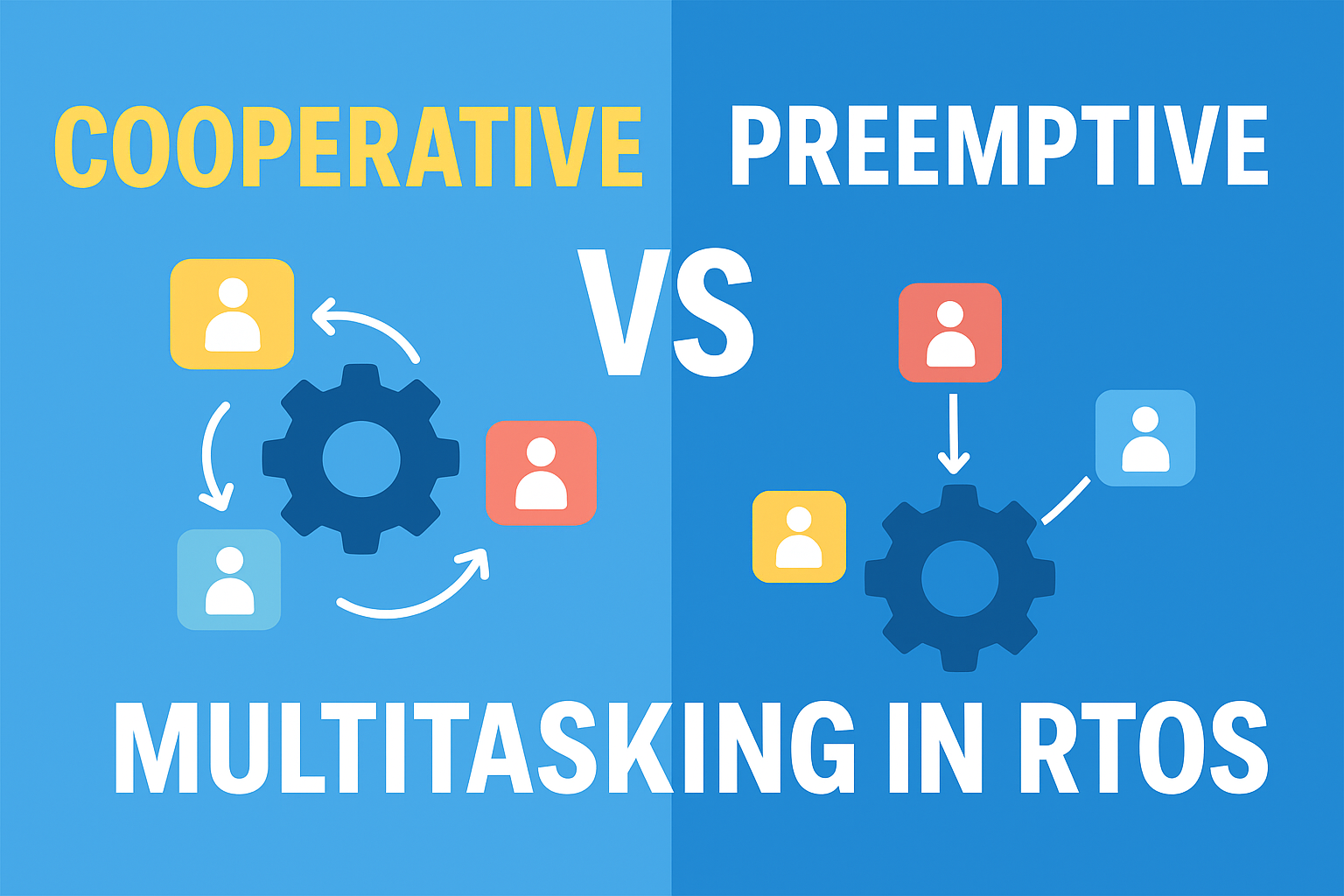
    • Cooperative Multitasking
    • Preemptive Multitasking

    Each model has its advantages, disadvantages, and specific use cases. To design efficient real-time systems, it is important to understand the trade-offs between cooperative multitasking and preemptive multitasking.

    What is Cooperative Multitasking?

    In a cooperative multitasking model, tasks voluntarily give up control of the CPU. This means the RTOS scheduler only switches tasks when a running task explicitly calls a yield function or completes execution.

    Key Characteristics of Trade-offs Between Cooperative and Preemptive Multitasking:

    • The CPU remains with a task until it decides to release control.
    • Context switching happens only at well-defined points.
    • The system depends on good behavior from tasks.

    Advantages of Cooperative Multitasking:

    • Simplicity: Easy to implement and understand.
    • Low Overhead: Fewer context switches mean more CPU time for tasks.
    • Predictability: Task switching occurs at known points, making debugging easier.

    Disadvantages of Cooperative Multitasking:

    • Risk of CPU Monopolization: A task that fails to yield can block the entire system.
    • Poor Real-Time Response: High-priority tasks may be delayed by long-running tasks.
    • Limited Scalability: Not suitable for complex applications with multiple time-critical tasks.

    Example Use Case: Small embedded systems such as calculators, digital watches, or basic IoT devices where tasks are lightweight and predictable.

    What is Preemptive Multitasking?

    In a preemptive multitasking model, the RTOS scheduler can interrupt tasks automatically based on priorities or timer ticks. This ensures that the CPU is allocated fairly and that high-priority tasks run without being blocked.

    Key Characteristics of Trade-offs Between Cooperative and Preemptive Multitasking:

    • The scheduler decides when to switch tasks.
    • High-priority tasks can preempt lower-priority ones immediately.
    • Requires proper handling of shared resources.

    Advantages of Preemptive Multitasking:

    • Fairness: No single task can monopolize the CPU.
    • High Responsiveness: Real-time deadlines can be met.
    • Better for Complex Systems: Can manage many tasks efficiently.

    Disadvantages of Preemptive Multitasking:

    • Higher Overhead: Frequent context switching consumes CPU time.
    • Increased Complexity: Requires synchronization mechanisms like mutexes and semaphores.
    • Harder to Debug: Bugs related to race conditions are more common.

    Example Use Case: Automotive systems, industrial automation, and medical devices where safety and real-time responsiveness are critical.

    Trade-offs Between Cooperative and Preemptive Multitasking Difference

    FactorCooperative MultitaskingPreemptive Multitasking
    CPU ControlTask decides when to yieldScheduler enforces switching
    OverheadLow (fewer context switches)Higher (frequent context switches)
    SimplicityEasy to implement and debugComplex, requires careful design
    FairnessDepends on task cooperationGuaranteed by scheduler
    ResponsivenessLimited, can cause delaysHigh, suitable for real-time systems
    Use CasesSimple devices, lightweight applicationsSafety-critical, time-sensitive systems

    Trade-offs Explained

    1. Performance vs Reliability:
      Cooperative multitasking has low overhead but risks reliability if a task fails to yield. Preemptive multitasking is more reliable but consumes more resources.
    2. Simplicity vs Complexity:
      Cooperative multitasking is beginner-friendly and easier to debug. Preemptive multitasking requires advanced concepts like mutexes, semaphores, and priority inversion handling.
    3. Responsiveness vs Determinism:
      Preemptive multitasking ensures timely responses, while cooperative multitasking offers deterministic but less responsive scheduling.

    When to Use Which?

    • Choose Cooperative Multitasking if:
      • The system is simple and predictable.
      • Tasks are lightweight and guaranteed to yield.
      • Power efficiency and low overhead are critical.
    • Choose Preemptive Multitasking if:
      • The system is complex with multiple critical tasks.
      • Real-time responsiveness is required.
      • Safety and fairness must be guaranteed.

    Conclusion of Trade-offs Between Cooperative and Preemptive Multitasking

    The choice between cooperative multitasking and preemptive multitasking in RTOS depends on the application’s needs.

    • Cooperative multitasking is simple, efficient, and suitable for small systems but risks delays if tasks do not yield.
    • Preemptive multitasking ensures fairness and responsiveness, making it ideal for safety-critical and real-time applications, but it comes with higher complexity and overhead.

    For most modern embedded systems, preemptive multitasking is preferred due to its reliability and ability to meet real-time constraints. However, cooperative multitasking still has its place in lightweight, power-constrained devices.

    FAQ: Trade-offs Between Cooperative and Preemptive Multitasking

    1. What is cooperative multitasking in RTOS?

    Cooperative multitasking is a model where tasks run until they voluntarily yield control to the scheduler. The RTOS depends on tasks being “well-behaved” and sharing CPU time responsibly.

    2. What is preemptive multitasking in RTOS?

    Preemptive multitasking allows the RTOS scheduler to forcibly interrupt tasks and allocate CPU time to higher-priority tasks. This ensures fairness and responsiveness but adds more complexity.

    3. Which model is easier to implement in an RTOS?

    Cooperative multitasking is easier to implement because it has lower overhead and requires minimal context switching. However, it relies heavily on proper task design.

    4. Why can cooperative multitasking cause delays?

    If a task does not yield control, it can block other tasks from executing, leading to delays, poor responsiveness, or even system freeze.

    5. Why is preemptive multitasking more reliable for real-time systems?

    Preemptive multitasking ensures that critical tasks always get CPU time when needed. This makes it more reliable for systems requiring strict real-time responses, such as automotive and medical devices.

    6. Which multitasking model has lower overhead?

    Cooperative multitasking has lower overhead because it avoids frequent context switches and reduces interrupt handling.

    7. Which multitasking model is more power-efficient?

    Cooperative multitasking can be more power-efficient in simple systems since fewer context switches reduce CPU load. However, preemptive multitasking can save power in real-time systems by ensuring tasks finish quickly and the CPU returns to idle mode.

    8. Can cooperative multitasking be used in critical systems?

    It can, but it is not recommended for safety-critical applications. Since one faulty or greedy task can block others, cooperative multitasking is risky for systems that require guaranteed timing.

    9. Is preemptive multitasking always better than cooperative multitasking?

    Not always. While preemptive multitasking ensures fairness and responsiveness, it also increases complexity, requires careful synchronization, and may waste CPU cycles due to frequent context switching.

    10. What is task starvation in cooperative multitasking?

    Task starvation occurs when a long-running task never yields control, preventing other tasks from executing. This problem is more common in cooperative systems.

    11. Do preemptive multitasking systems require synchronization mechanisms?

    Yes. Since tasks can be interrupted at any time, synchronization tools like semaphores, mutexes, and message queues are required to prevent data corruption and race conditions.

    12. Which multitasking model is best for beginners learning RTOS concepts?

    Beginners often start with cooperative multitasking because it is easier to understand and debug. Once comfortable, they move to preemptive multitasking for real-world, time-critical applications.

    Trade-offs Between Cooperative and Preemptive Multitasking
    Trade-offs Between Cooperative and Preemptive Multitasking in RTOS Master RTOS Interview Questions (2025)
  • What is a Semaphore in FreeRTOS? | Master RTOS Interview Questions (2026)

    Semaphore in FreeRTOS : Learn what a semaphore is in FreeRTOS with beginner-friendly examples. Understand binary semaphores, counting semaphores, and mutexes with code, FAQs, and real-world use cases.

    When you start learning FreeRTOS, one of the first synchronization tools you will come across is the semaphore. If you are confused about what a semaphore is and how it works, don’t worry — this guide will explain everything step by step in simple language.

    What is a Semaphore in FreeRTOS?

    Think of a semaphore as a kind of signal or token that tasks use to communicate or control access to resources in FreeRTOS.

    It is commonly used for:

    1. Synchronization – making one task wait until another task or interrupt gives a signal.
    2. Resource Management – controlling access to something that only one task should use at a time (like a printer, sensor, or shared variable).

    Simple Real-Life Example of Semaphore in FreeRTOS

    Imagine there is one bathroom (shared resource) in a house with three people (tasks).

    • The bathroom has a key (semaphore).
    • If the bathroom is free, the key is available.
    • A person (task) must take the key before entering.
    • While someone is inside, no one else can enter (they must wait until the key is returned).
    • Once done, the key is placed back, and another person can take it.

    👉 The key is the semaphore, ensuring only one task uses the bathroom at a time.

    Types of Semaphores in FreeRTOS

    1. Binary Semaphore
      • Has only two states: taken (0) or available (1).
      • Example: Used to signal from an interrupt to a task (like “Button pressed → Task wakes up”).
    2. Counting Semaphore
      • Has a count value (0, 1, 2, … N).
      • Example: Useful when multiple identical resources are available (like 3 parking spots).
    3. Mutex (Mutual Exclusion Semaphore)
      • Special type of binary semaphore used for protecting shared resources (like global variables or hardware).
      • Has extra features like priority inheritance (helps prevent priority inversion problems).

    How Semaphore work in FreeRTOS

    • xSemaphoreTake() → A task tries to take the semaphore (waits if not available).
    • xSemaphoreGive() → A task (or ISR) releases the semaphore (signals it’s free).

    Code Example (Binary Semaphore)

    #include "FreeRTOS.h"
    #include "semphr.h"
    
    SemaphoreHandle_t xBinarySemaphore;
    
    void ISR_ButtonPress(void) {
        // Give semaphore when button pressed
        xSemaphoreGiveFromISR(xBinarySemaphore, NULL);
    }
    
    void Task_WaitForButton(void *pvParameters) {
        for(;;) {
            if (xSemaphoreTake(xBinarySemaphore, portMAX_DELAY)) {
                // Runs when button is pressed
                printf("Button Pressed! Task Running...\n");
            }
        }
    }
    
    int main(void) {
        xBinarySemaphore = xSemaphoreCreateBinary();
        xTaskCreate(Task_WaitForButton, "ButtonTask", 1000, NULL, 1, NULL);
        vTaskStartScheduler();
    }
    

    👉 In this example:

    • The ISR gives the semaphore when the button is pressed.
    • The task waits until the semaphore is available, then runs its code.

    In short:
    A semaphore in FreeRTOS is like a key or signal that tasks and interrupts use to coordinate actions and control shared resources safely.

    1) Core idea (mental model) of Semaphore in FreeRTOS

    A semaphore is a small counter inside the kernel that tasks (and sometimes ISRs) use to signal events and/or control access to something.

    • When a task takes it and the counter is > 0, the counter decrements and the task continues.
    • If the counter is 0, the task blocks (waits) until somebody gives it (increments the counter or “posts a signal”).

    Under the hood in FreeRTOS, semaphores are implemented using the queue mechanism. So every semaphore is really a special queue with length 1 (binary/mutex) or >1 (counting).

    2) The three flavors and when to use each of Semaphore in FreeRTOS

    A) Binary semaphore — signal between contexts

    • Counter can be 0 or 1.
    • Perfect for task ↔ interrupt or task ↔ task signaling like “button pressed”, “DMA complete”, “sensor ready”.
    • No ownership and no priority inheritance. Any task/ISR can give, any task can take.

    B) Counting semaphore — N identical things / event counting

    • Counter ranges 0..N.
    • Use it either to:
      1. represent N identical resources (e.g., 3 UART channels, 4 buffers), or
      2. count events (e.g., an ISR “gives” once per pulse; a task consumes pulses by “taking”).
    • No ownership, no priority inheritance.

    Let’s understand both with simple examples 👇

    1. Binary Semaphore

    • Value: Can be either 0 or 1 (just like a light switch: ON/OFF).
    • Use: Allows only one task to access a resource at a time.
    • Once a task takes it, others must wait until it’s released.

    💡 Example:

    • Imagine a toilet with a lock 🚻
      • If it’s free (1) → someone can go inside.
      • Once someone enters, it becomes locked (0) → others must wait outside.
      • When the person comes out, they unlock it (back to 1) → next person can enter.

    👉 This is why it’s often used for mutual exclusion (mutex-like behavior).

    2. Counting Semaphore

    • Value: Can be any non-negative number (not just 0 or 1).
    • Use: Allows multiple tasks to access a limited number of resources.

    💡 Example:

    • Imagine a parking lot with 5 spaces 🚗🚗🚗🚗🚗
      • Semaphore starts at 5.
      • Each car that parks → reduces count by 1.
      • If count reaches 0 → no parking space left, cars must wait.
      • When a car leaves → count increases by 1 (a space is free again).

    👉 This is used when several instances of a resource are available.

    C) Mutex (Mutual Exclusion Semaphore) — protect a shared resource

    • Behavior looks like a binary semaphore but it has ownership and priority inheritance.
    • Use for critical sections around shared state or drivers (e.g., I²C bus, shared log buffer).
    • Only tasks may use mutexes (not ISRs). Mutex “owner” must be the one to release it.

    The word “Mutual Exclusion” (often shortened to Mutex) means:
    👉 Only one task or process can use a shared resource at a time, and others must wait until it’s free.

    Example in Real Life

    Imagine:

    • You and your friend want to use the same pen ✏️.
    • If both of you grab it at the same time, the pen might break or neither can write properly.
    • So, you agree on a rule:
      • Whoever takes the pen first → uses it alone.
      • The other person must wait.
      • Once the first person is done, they give back the pen.

    👉 This “rule” is mutual exclusion — making sure only one person uses the shared resource at a time.

    Priority inheritance: If a high-priority task waits on a mutex held by a lower-priority task, the kernel temporarily “boosts” the lower-priority task so it can finish and release the mutex quickly. This minimizes priority inversion.

    3) API quick tour (most-used) of Semaphore in FreeRTOS

    • Create:
      • xSemaphoreCreateBinary() / xSemaphoreCreateBinaryStatic()
      • xSemaphoreCreateCounting(UBaseType_t max, UBaseType_t initial)
      • xSemaphoreCreateMutex() / xSemaphoreCreateRecursiveMutex()
    • Take (block up to xTicksToWait):
      • xSemaphoreTake(SemaphoreHandle_t, TickType_t xTicksToWait)
      • xSemaphoreTakeRecursive() (for recursive mutexes)
    • Give:
      • xSemaphoreGive() (tasks only)
      • xSemaphoreGiveFromISR() (for binary/counting semaphores from ISRs)
      • xSemaphoreGiveRecursive() (for recursive mutex)

    Timeouts: pass pdMS_TO_TICKS(ms) for readability. portMAX_DELAY means “wait forever” (if configured to allow that).

    4) Blocking, timeouts, and wake-up order of Semaphore in FreeRTOS

    • If a task calls xSemaphoreTake() and the semaphore is unavailable, it blocks for up to xTicksToWait.
    • When the semaphore becomes available, the highest-priority waiting task gets it.
    • If several waiting tasks have the same priority, the one waiting longest runs first (FIFO among equals).

    5) ISR rules (super important) of Semaphore in FreeRTOS

    • You may not block in an ISR. So never call xSemaphoreTake() in an ISR.
    • To signal from an ISR, use xSemaphoreGiveFromISR() (binary/counting only).
    • Capture the “woken” flag and request a context switch:
    void ISR_Handler(void)
    {
        BaseType_t xHigherPriorityTaskWoken = pdFALSE;
        xSemaphoreGiveFromISR(xBinSem, &xHigherPriorityTaskWoken);
        portYIELD_FROM_ISR(xHigherPriorityTaskWoken); // or portEND_SWITCHING_ISR(...)
    }
    
    • Never use mutexes in ISRs.

    6) Creation: initial state & static vs dynamic of Semaphore in FreeRTOS

    • xSemaphoreCreateBinary() returns a semaphore with count = 0.
      • If you want the first xSemaphoreTake() to succeed immediately, give it once after creation.
    • Counting semaphores: choose maxCount and initialCount.
    • Prefer static creation on tiny MCUs to avoid heap use:
      • xSemaphoreCreateBinaryStatic(StaticSemaphore_t *buffer) etc.

    7) Common patterns (and code) of Semaphore in FreeRTOSd

    Pattern 1: ISR → Task signal (binary semaphore)

    Use when an interrupt should wake a task to do the heavy work.

    #include "FreeRTOS.h"
    #include "task.h"
    #include "semphr.h"
    
    static SemaphoreHandle_t xBtnSem;
    
    void EXTI_ButtonISR(void) // called on rising edge, for example
    {
        BaseType_t hpTaskWoken = pdFALSE;
        xSemaphoreGiveFromISR(xBtnSem, &hpTaskWoken);
        portYIELD_FROM_ISR(hpTaskWoken);
    }
    
    static void vButtonTask(void *arg)
    {
        for (;;)
        {
            // Wait indefinitely until ISR signals
            if (xSemaphoreTake(xBtnSem, portMAX_DELAY) == pdTRUE)
            {
                // Debounce / handle press
                // ...
            }
        }
    }
    
    void app_init(void)
    {
        xBtnSem = xSemaphoreCreateBinary();
        configASSERT(xBtnSem != NULL);
    
        // Optional: if you want the first take to pass immediately
        // xSemaphoreGive(xBtnSem);
    
        xTaskCreate(vButtonTask, "Btn", 512, NULL, tskIDLE_PRIORITY + 2, NULL);
        vTaskStartScheduler();
    }
    

    Pattern 2: N identical resources (counting semaphore)

    Let up to 3 tasks use a resource simultaneously.

    static SemaphoreHandle_t xSlots; // 3 slots
    
    void app_init(void)
    {
        xSlots = xSemaphoreCreateCounting(3, 3); // max=3, initial=3 (all free)
        configASSERT(xSlots);
    }
    
    void vWorker(void *arg)
    {
        for (;;)
        {
            if (xSemaphoreTake(xSlots, pdMS_TO_TICKS(1000)) == pdTRUE)
            {
                // Use one slot
                // ... do work ...
                xSemaphoreGive(xSlots); // release slot
            }
            else
            {
                // Timeout handling (no slot available)
            }
        }
    }
    

    Pattern 3: Protect a shared driver or data (mutex with PI)

    static SemaphoreHandle_t xI2CMutex;
    
    void app_init(void)
    {
        xI2CMutex = xSemaphoreCreateMutex();
        configASSERT(xI2CMutex);
    }
    
    void vSensorTask(void *arg)
    {
        for (;;)
        {
            if (xSemaphoreTake(xI2CMutex, pdMS_TO_TICKS(50)) == pdTRUE)
            {
                // Exclusive access to I2C
                // i2c_start(); i2c_txrx(); ...
                xSemaphoreGive(xI2CMutex);
            }
            else
            {
                // Couldn’t get the bus in time
            }
        }
    }
    

    Pattern 4: Recursive mutex (same task re-enters)

    Only use if a function may need to lock the same mutex multiple times from the same task (e.g., library calls that call back into you).

    static SemaphoreHandle_t xCfgMutex;
    
    void app_init(void)
    {
        xCfgMutex = xSemaphoreCreateRecursiveMutex();
        configASSERT(xCfgMutex);
    }
    
    void config_update_A(void)
    {
        if (xSemaphoreTakeRecursive(xCfgMutex, pdMS_TO_TICKS(100)))
        {
            // ... modify part A ...
            // Maybe call another function that also takes the same mutex:
            config_update_B();
            xSemaphoreGiveRecursive(xCfgMutex);
        }
    }
    

    8) Choosing the right tool (cheatsheet) of Semaphore in FreeRTOS

    • Just wake a task from an ISR?
      • Use binary semaphore, or even better: Direct-to-Task Notifications (lighter & faster).
    • Pool of identical resources / event bursts?
      • Counting semaphore.
    • Protect a shared resource in task context?
      • Mutex (gets you priority inheritance).
    • Set/clear multiple condition bits?
      • Consider Event Groups.
    • Pass data bytes/structs?
      • Use a Queue (semaphores don’t carry data).

    Direct-to-Task Notification vs Binary Semaphore
    Task notifications are a per-task lightweight counter/bitfield. They are faster and use no extra RAM. Prefer them when a semaphore is only used to wake one specific task.

    9) Pitfalls and how to avoid them of Semaphore in FreeRTOS

    • Using a mutex from an ISR: not allowed. Use binary/counting sem + xSemaphoreGiveFromISR.
    • Priority inversion with a binary semaphore: binary semaphores lack priority inheritance; if you need PI, use a mutex.
    • Deadlocks (two tasks take A then B in different orders): always acquire multiple mutexes in a fixed global order.
    • Starvation: a low-priority task might rarely get the mutex if higher-priority tasks hold/retake it often. Keep critical sections short.
    • Lost first event: xSemaphoreCreateBinary() starts at 0; if your task waits immediately, ensure the producer gives after creation (or you give once during init).
    • Overrun with counting semaphores: if the ISR “gives” faster than the consumer “takes”, the count tops out at maxCount; further events are dropped. Pick a suitable maxCount or drain faster.
    • Blocking forever by mistake: consider timeouts and fallback logic unless “must wait” is intended.

    10) Timing & configuration tips of Semaphore in FreeRTOS

    • Convert milliseconds to ticks with pdMS_TO_TICKS(ms).
    • portMAX_DELAY means “wait forever” only if configured (depends on INCLUDE_vTaskSuspend / tickless).
    • In tiny systems, prefer static creation to avoid heap fragmentation.
    • Keep critical sections as short as possible to maintain system responsiveness.

    11) Quick decision flow of Semaphore in FreeRTOS

    1. Do I need to pass data? → Queue.
    2. Just need to wake a task? → Task notification (or binary sem if multiple producers).
    3. Need N identical tokens? → Counting sem.
    4. Need to protect shared resource in tasks + avoid priority inversion? → Mutex (or recursive mutex if re-entrancy is required).

    Frequently Asked Questions (FAQ) on Semaphores in FreeRTOS

    1. What is a semaphore in FreeRTOS?

    A semaphore in FreeRTOS is a synchronization tool used by tasks and interrupts to signal events or control access to shared resources. It works like a token that tasks must take before using a resource and give back after finishing.

    2. What are the types of semaphores in FreeRTOS?

    FreeRTOS provides three types of semaphores:

    • Binary Semaphore → Used for simple signaling (available or not).
    • Counting Semaphore → Used when multiple resources are available or for event counting.
    • Mutex (Mutual Exclusion) → Used to protect shared resources and prevent priority inversion.

    3. What is the difference between a binary semaphore and a mutex?

    • Binary Semaphore → Can be given and taken by any task or ISR, mainly used for signaling.
    • Mutex → Has ownership (only the task that takes it can release it) and includes priority inheritance, making it ideal for protecting shared resources.

    4. Can semaphores be used inside an ISR in FreeRTOS?

    • Yes, but only binary and counting semaphores can be used inside an ISR using xSemaphoreGiveFromISR().
    • Mutexes cannot be used inside ISRs because they require task ownership and priority inheritance.

    5. What is the difference between a counting semaphore and a binary semaphore?

    • Binary Semaphore → Can only have values 0 or 1 (like a simple flag).
    • Counting Semaphore → Can count multiple resources or events (0 to N).

    6. What happens if a task cannot take a semaphore immediately?

    If a semaphore is not available, the task will either:

    • Block (wait) for a specified time (xTicksToWait), or
    • Timeout if the wait period expires without success.

    7. When should I use a semaphore vs a queue in FreeRTOS?

    • Use a semaphore when you just need signaling or mutual exclusion.
    • Use a queue when you need to send actual data between tasks or from ISR to a task.

    8. Are semaphores and task notifications the same in FreeRTOS?

    Not exactly.

    • Semaphores are flexible and can be shared between tasks.
    • Task notifications are lighter and faster but tied to a specific task.

    9. What is priority inheritance in mutexes?

    If a high-priority task is waiting for a mutex held by a low-priority task, FreeRTOS temporarily boosts the low-priority task’s priority. This helps it release the mutex quickly, preventing priority inversion.

    10. Which semaphore should I use for protecting shared variables in FreeRTOS?

    Use a mutex because it provides mutual exclusion and prevents priority inversion.

    Semaphore in FreeRTOS
    What is a Semaphore in FreeRTOS Master RTOS Interview Questions (2025)
  • 100 FreeRTOS Interview Questions for Embedded Systems Engineers | Master RTOS Interview Questions (2026)

    100 FreeRTOS Interview Questions : FreeRTOS is one of the most popular real-time operating systems used in embedded systems, IoT devices, and automotive applications. If you are preparing for an embedded software interview, you will likely encounter questions related to RTOS concepts, FreeRTOS internals, task scheduling, synchronization mechanisms, and memory management.

    This guide provides a complete list of 100 FreeRTOS interview questions — ranging from beginner to advanced — to help you prepare effectively for your next embedded systems interview.

    Why FreeRTOS Interview Questions Matter?

    • FreeRTOS is widely used in automotive, aerospace, IoT, consumer electronics, and industrial systems.
    • Companies test candidates on conceptual understanding and hands-on experience with FreeRTOS.
    • Covering these questions will strengthen your RTOS fundamentals and improve your problem-solving ability in real-time environments.

    FreeRTOS Interview Questions List

    Here are the top 100 FreeRTOS interview questions, categorized for easier preparation:

    1. FreeRTOS Interview Questions Basics

    1. What is an RTOS?
    2. What are the key features of an RTOS?
    3. What is the difference between an RTOS and a general-purpose operating system?
    4. Explain the concept of a task in an RTOS.
    5. What is a context switch in an RTOS?
    6. How does an RTOS handle interrupts?
    7. What is the purpose of a scheduler in an RTOS?
    8. Describe the task states in an RTOS.

    2. FreeRTOS Interview Questions Fundamentals

    1. What is a semaphore in FreeRTOS?
    2. Explain the concept of priority inversion.
    3. What is a mutex and when would you use it in an RTOS?
    4. How does a FreeRTOS application handle memory management?
    5. What is a stack overflow and how can it be prevented in an RTOS?
    6. Describe the concept of preemption in an RTOS.
    7. What is a tick in FreeRTOS?
    8. How does a tick interrupt affect an RTOS application?
    9. Explain the concept of blocking and non-blocking tasks.
    10. What is the purpose of an idle task in FreeRTOS?

    3. FreeRTOS Interview Questions Task Scheduling and Management

    1. How does an RTOS handle inter-task communication?
    2. What are the advantages and disadvantages of using an RTOS?
    3. What are the main components of FreeRTOS?
    4. Describe the architecture of FreeRTOS.
    5. How does FreeRTOS handle real-time constraints?
    6. What is the difference between a cooperative and a preemptive RTOS?
    7. Explain the role of the tick interrupt handler in FreeRTOS.
    8. How does an RTOS handle task scheduling?
    9. What is a timer in FreeRTOS?
    10. Describe the use of queues in FreeRTOS.

    4. FreeRTOS Interview Questions Synchronization and Communication

    1. How does an RTOS handle priority inversion?
    2. What is a critical section in an RTOS?
    3. Explain the concept of task notifications in FreeRTOS.
    4. What is the purpose of an event group in FreeRTOS?
    5. How does an RTOS handle resource sharing among tasks?
    6. Describe the concept of time slicing in an RTOS.
    7. What is the role of a software timer in FreeRTOS?
    8. Explain the concept of task suspension in FreeRTOS.
    9. How does an RTOS handle dynamic memory allocation?
    10. What are the different scheduling algorithms used in an RTOS?

    5. FreeRTOS Interview Questions Advanced FreeRTOS Features

    1. Describe the use of task notifications in FreeRTOS.
    2. How does an RTOS handle priority inversion?
    3. Explain the concept of interrupt nesting in FreeRTOS.
    4. What is the purpose of a tickless idle mode in FreeRTOS?
    5. Describe the concept of a tickless scheduler in an RTOS.
    6. How does an RTOS handle stack overflow detection?
    7. What is the purpose of a tick hook function in FreeRTOS?
    8. Explain the concept of time delay in FreeRTOS.
    9. How does an RTOS handle power management?
    10. What is the role of a software watchdog in FreeRTOS?

    6. FreeRTOS Interview Questions Multi-Core and Resource Handling

    1. Describe the concept of an application hook function in FreeRTOS.
    2. How does an RTOS handle multiple processor cores?
    3. What is the purpose of a task handle in FreeRTOS?
    4. Explain the concept of tickless operation in an RTOS.
    5. How does an RTOS handle software timers?
    6. What is the role of a tick interrupt in FreeRTOS?
    7. Describe the use of a binary semaphore in FreeRTOS.
    8. How does an RTOS handle synchronization between tasks?
    9. What is the purpose of a tickless timer in FreeRTOS?
    10. Explain the concept of stack overflow protection in an RTOS.

    7. FreeRTOS Interview Questions Memory and Error Handling

    1. How does an RTOS handle task synchronization?
    2. What are the main components of an RTOS?
    3. What is the purpose of an idle task hook in FreeRTOS?
    4. Explain the concept of task notification value in FreeRTOS.
    5. How does an RTOS handle inter-task communication using message queues?
    6. What is the role of a task switch hook in FreeRTOS?
    7. Describe the use of counting semaphores in FreeRTOS.
    8. How does an RTOS handle dynamic memory allocation in a multitasking environment?
    9. What is the purpose of an application-defined stack overflow hook in FreeRTOS?
    10. Explain the concept of a tickless idle hook in an RTOS.

    8. FreeRTOS Interview Questions Hooks, Timers, and Delays

    1. How does an RTOS handle task prioritization?
    2. Describe the use of recursive mutexes in FreeRTOS.
    3. What is the role of a timer service in FreeRTOS?
    4. How does an RTOS handle time management?
    5. What is the purpose of an application-defined malloc failed hook in FreeRTOS?
    6. Explain the concept of a software interrupt in FreeRTOS.
    7. How does an RTOS handle thread-safe memory allocation?
    8. Describe the use of task notifications in inter-process communication in FreeRTOS.
    9. What is the role of a software timer hook in FreeRTOS?
    10. How does an RTOS handle task synchronization using event groups?

    9. FreeRTOS Interview Questions Communication and Task Control

    1. What is the purpose of a memory pool in FreeRTOS?
    2. Explain the concept of cooperative multitasking in an RTOS.
    3. How does an RTOS handle task synchronization using binary semaphores?
    4. Describe the use of direct to task notifications in FreeRTOS.
    5. What is the role of a stack overflow hook in FreeRTOS?
    6. How does an RTOS handle task scheduling using round-robin algorithm?
    7. What is the purpose of a task delay until function in FreeRTOS?
    8. Explain the concept of a stream buffer in an RTOS.
    9. How does an RTOS handle priority-based preemption?
    10. Describe the use of inter-task communication using DMA in FreeRTOS.

    10. FreeRTOS Interview Questions Multi-Core, Notifications, and Performance

    1. What is the role of a task tag in FreeRTOS?
    2. How does an RTOS handle task synchronization using event flags?
    3. What is the purpose of a task resume function in FreeRTOS?
    4. Explain the concept of a message buffer in FreeRTOS.
    5. How does an RTOS handle task scheduling in a multi-core environment?
    6. Describe the use of priority inheritance protocol in FreeRTOS.
    7. What is the role of a task notification hook in FreeRTOS?
    8. How does an RTOS handle interrupt latency?
    9. What is the purpose of a task notification hook in FreeRTOS?
    10. Explain the concept of priority-based interrupt nesting in an RTOS.
    11. How does an RTOS handle task synchronization using software queues?
    12. Describe the use of memory pools in dynamic memory allocation in FreeRTOS.

    Tips to Prepare for FreeRTOS Interview Questions

    • Understand RTOS fundamentals: scheduling, synchronization, tasks, ISRs.
    • Practice writing FreeRTOS applications using semaphores, queues, and timers.
    • Explore FreeRTOS source code for deeper understanding.
    • Learn real-time debugging techniques (stack usage, trace tools, GDB).
    • Review embedded C/C++ basics since coding skills are always tested.

    Conclusion

    This comprehensive list of 100 FreeRTOS interview questions covers everything from basic RTOS concepts to advanced FreeRTOS features. By mastering these questions, you can confidently face interviews for embedded systems, IoT development, and real-time software engineering roles.

    FreeRTOS Interview Questions
    100 FreeRTOS Interview Questions for Embedded Systems Engineers Master RTOS Interview Questions (2025)