Author: admin

  • Architecture of CAN Bus System | Master CAN Interview Questions (2026)

    Architecture of CAN Bus System: The Controller Area Network (CAN) bus system is a popular communication protocol widely used in automotive and industrial applications. It allows multiple electronic control units (ECUs) to communicate with each other efficiently over just two wires. In this article, we will explain the basic architecture of a CAN bus system in simple terms, making it easy for beginners to understand.

    Learn the basic architecture of a CAN bus system in this beginner-friendly guide. Understand key components like ECUs, CAN-High and CAN-Low wiring, message framing, and arbitration. Perfect for anyone starting with automotive or embedded communication protocols.

    What is a CAN Bus System?

    A CAN bus system is a robust vehicle bus standard designed to allow microcontrollers and devices to communicate without a host computer. It is especially useful in environments with high electrical noise, like cars, where reliable communication between multiple ECUs is essential.

    Key Components of CAN Bus Architecture

    1. Nodes (Electronic Control Units – ECUs)

    Each device or node in a CAN bus system contains:

    • A Microcontroller (MCU) that processes data.
    • A CAN controller that manages message framing, error detection, and protocol handling.
    • A CAN transceiver that converts data to and from the physical bus lines.

    Nodes can both send and receive messages on the bus, making CAN a multi-master system.

    2. Bus Lines: CAN-High and CAN-Low

    Communication takes place over two wires called CAN-High (CAN-H) and CAN-Low (CAN-L). These wires carry differential signals, meaning one wire carries the inverse of the other. This helps the system resist electrical noise and improves data integrity.

    3. Termination Resistors

    At both ends of the CAN bus, 120-ohm resistors are connected to prevent signal reflections and ensure reliable communication.

    Layers in the Architecture of the CAN Bus

    CAN bus architecture follows international standards defined by ISO 11898. It primarily works on two layers of the OSI model:

    • Physical Layer (ISO 11898-2): Defines wiring, signal voltage levels, and data rates. The twisted pair of CAN-H and CAN-L cables operate at speeds up to 1 Mbps (Classical CAN) or higher in CAN FD.
    • Data Link Layer (ISO 11898-1): Handles message framing, arbitration (which node gets to transmit when multiple nodes start transmitting simultaneously), error detection, and message acknowledgment.

    How CAN Bus Communication Works

    • Message Framing:
      Messages, or frames, consist of an identifier, data length, data payload (up to 8 bytes in Classical CAN), CRC for error checking, and control bits.
    • Arbitration:
      When multiple nodes send messages simultaneously, the one with the highest priority (lowest identifier number) wins the bus without data loss. This process is called arbitration.
    • Error Handling:
      CAN automatically detects errors and retransmits faulty messages, ensuring reliable communication.

    CAN Bus Physical Design and Topology

    The standard CAN bus uses a linear topology, where all nodes are connected along a single pair of wires with termination resistors at each end. This layout reduces reflections and interference.

    CAN Protocol Block Diagram — Overview

    The CAN bus follows a multi-master bus architecture, which means that any node (or ECU) connected to the bus can send or receive messages at any time. It also has built-in error handling to keep communication reliable.

    The main part of the CAN system is called the CAN core. This core acts like a memory-mapped device to the host processor and is responsible for sending and receiving CAN messages (called frames). It can be integrated easily with the host using standard interfaces like APB (Advanced Peripheral Bus) or AHB-Lite (Advanced High-performance Bus Lite), depending on performance and power needs.

    Key Parts Inside the CAN Core

    • Acceptance Filters: These help the system decide which messages should be accepted or ignored, making sure the ECU only processes relevant data.
    • Interrupts: Programmable signals to alert the processor about new messages or errors.
    • Buffers: Memory areas for storing messages before sending or after receiving.
      • There are two types of transmit buffers:
        • Primary Transmission Buffer (PTB): Holds high-priority messages.
        • Secondary Transmission Buffer (STB): Stores lower-priority messages.
      • Buffers work in a First-In-First-Out (FIFO) manner in priority mode.

    CAN Bus Layered Architecture

    The CAN communication protocol is defined by the ISO 11898 standard and has two main layers:

    1. Data Link Layer:
      This layer manages how data is sent between nodes, error checking, and message prioritization. It has two sublayers:
      • MAC (Medium Access Control): Controls which node can use the bus at a given time and handles framing and error detection.
      • LLC (Logical Link Control): Handles flow control, error recovery, and acceptance filtering.
    2. Physical Layer:
      This layer defines how the data is physically transmitted over the wires — including voltage levels, timing, and connectors. It consists of:
      • PCS (Physical Coding Sublayer): Encodes and decodes the bits on the bus.
      • PMA (Physical Medium Attachment): Handles framing and synchronization of bits.
      • PMD (Physical Medium Dependent): Deals with actual transmission and reception of bits on the wire.
      • MDI (Medium Dependent Interface): The physical connection to the network medium (cables).

    How CAN Bus Works — Data Transmission and Arbitration

    • CAN Frames:
      Data is sent in packets called frames. Each frame includes a unique identifier (priority), control bits, data payload, and error-checking codes.
    • Multi-Master and Arbitration:
      Multiple nodes can try to send data at the same time. To avoid collisions, CAN uses arbitration — a method that prioritizes messages with lower identifier numbers. The node with the highest priority continues to send, while others wait.
    • Bit Monitoring:
      While sending data, each node listens to the bus to make sure the bit they sent matches what is on the bus. If not, it means another node has a higher priority message, so the lower priority node stops transmitting.

    Example of Arbitration in the Architecture of the CAN Bus

    Imagine two ECUs want to send messages simultaneously:

    • ECU 1 has an identifier 0x234
    • ECU 2 has an identifier 0x352

    CAN uses wired-AND logic, meaning a dominant bit (0) overrides a recessive bit (1). When both ECUs transmit the third bit, ECU 1 sends 0 and ECU 2 sends 1. The bus reads 0 (dominant). ECU 2 detects the difference and stops transmitting, letting ECU 1 continue because it has higher priority.

    Standard CAN Frame Format

    Here’s what a typical CAN message frame looks like (in the standard 11-bit format):

    FieldDescription
    SOF (Start of Frame)Indicates the beginning of a message (1 bit)
    IdentifierDefines message priority (11 bits)
    RTR (Remote Transmission Request)Distinguishes between data and remote frames (1 bit)
    Control FieldContains user-specified flags
    IDE (Identifier Extension)Indicates if frame is standard (11-bit) or extended (29-bit)
    DLC (Data Length Code)Specifies number of data bytes (4 bits)
    Data FieldContains up to 8 bytes of actual data
    CRC (Cyclic Redundancy Check)Error-checking code (15 bits)
    ACK (Acknowledgement)Confirms correct reception (2 bits)
    EoF (End of Frame)Marks the end of the message (7 bits)

    Summary Architecture of the CAN Bus

    CAN Bus ElementDescription
    Nodes (ECUs)Devices with MCU, CAN controller, and transceiver
    CAN-High and CAN-LowTwisted pair differential signaling wires
    Termination Resistors120 Ω resistors at bus ends to prevent reflections
    Physical Layer (ISO 11898-2)Defines wiring and signaling specifications
    Data Link Layer (ISO 11898-1)Manages message framing, arbitration, and error handling
    ArbitrationPriority-based bus access control

    Conclusion

    The CAN bus system is a simple yet powerful communication protocol enabling multiple devices to communicate over a shared two-wire bus efficiently. Its architecture combines robust physical wiring, standardized messaging, and smart arbitration techniques to ensure data integrity in noisy environments like vehicles. Understanding its basic components and working principle is essential for anyone diving into embedded systems or automotive electronics.

    1. What is the CAN bus system?

    The CAN (Controller Area Network) bus system is a robust communication protocol used primarily in automotive and industrial applications to allow microcontrollers and devices to communicate with each other without a host computer. It enables multiple nodes to share data efficiently over a single two-wire bus.

    2. How is the architecture of a CAN bus system structured?

    The CAN bus architecture consists of several nodes connected through a twisted pair cable. Each node contains a CAN controller and a transceiver. The controller manages data framing, error checking, and message filtering, while the transceiver converts the controller’s digital signals to differential signals for the bus.

    3. What are the main components of a CAN node?

    A typical CAN node has three main parts: the microcontroller (which runs the application), the CAN controller (which handles CAN protocol functions), and the CAN transceiver (which interfaces with the physical bus).

    4. What type of bus topology does CAN use?

    CAN uses a multi-master, broadcast communication bus topology. This means any node can start transmitting data when the bus is free, and messages are broadcast to all nodes simultaneously.

    5. How does CAN handle message priority?

    CAN uses message identifiers to determine priority. Lower numerical values of identifiers have higher priority on the bus, allowing critical messages to get transmitted first during bus arbitration.

    6. What is bus arbitration in CAN?

    Bus arbitration is the process by which multiple nodes attempt to transmit data simultaneously. CAN uses a nondestructive arbitration method based on message priority, ensuring the highest priority message gains bus access without data loss.

    7. How does CAN ensure data integrity and error handling?

    CAN includes several error detection mechanisms such as CRC (Cyclic Redundancy Check), bit stuffing, acknowledgment checks, and error flags. When an error is detected, nodes retransmit messages to maintain data reliability.

    8. Why is CAN preferred in automotive systems?

    CAN is highly reliable, efficient, and cost-effective. It supports real-time communication with robust error handling and allows many electronic control units (ECUs) to communicate over a simple two-wire bus, making it ideal for automotive applications.

    9. Can CAN bus systems support long distances and high speeds?

    CAN supports data rates up to 1 Mbps and bus lengths typically up to 40 meters at the highest speed. For longer distances, the speed is reduced to maintain signal integrity.

    10. What is the difference between CAN 2.0A and CAN 2.0B?

    CAN 2.0A supports standard frames with 11-bit identifiers, whereas CAN 2.0B supports extended frames with 29-bit identifiers, allowing for more message identifiers and better flexibility.
  • What is Bit Stuffing in CAN Bus Communication? | Master CAN Interview Questions (2026)

    Bit Stuffing in CAN (Controller Area Network) is a technique used to ensure reliable data transmission by inserting extra bits into the data stream. This prevents long sequences of identical bits, helping maintain synchronization between sender and receiver. In this article, we explain what bit stuffing is, why it’s essential in CAN communication, and how it works with real-world examples, making it easy for beginners and professionals to understand.

    Introduction – Bit Stuffing in CAN Bus

    If you’ve ever worked with CAN (Controller Area Network) bus communication, you may have come across the term bit stuffing. At first, it might sound like some tricky technical jargon, but in reality, it’s a clever way to keep communication smooth, synchronized, and error-free.

    In this article, we’ll break down what bit stuffing is, why it’s essential in CAN communication, and how it works — in plain, beginner-friendly language.

    1. What Is Bit Stuffing?

    Bit stuffing is a technique used in CAN communication where a complementary bit is inserted into the data stream after five consecutive identical bits.

    • If there are five 1s in a row → insert a 0.
    • If there are five 0s in a row → insert a 1.

    This happens automatically:

    • Transmitter: Adds the stuffed bit.
    • Receiver: Detects and removes it before processing the data.

    📌 Think of it like this:
    If a teacher is reading a long sentence without pauses, students might lose track. A small pause (bit stuffing) ensures everyone stays in sync.

    2. Why Is Bit Stuffing Used in CAN Bus?

    a) Clock Synchronization

    CAN is asynchronous, meaning it doesn’t send a separate clock signal.

    • Receivers synchronize their internal clocks by detecting changes (edges) in the signal.
    • If there are too many identical bits in a row, there are no edges, and synchronization is lost.
    • Bit stuffing ensures enough transitions for accurate timing.

    b) Preventing False Frame Detection

    Some bit patterns (like a long string of 0s or 1s) are used for special markers in CAN, such as Start of Frame (SOF) or End of Frame (EOF).

    • Without bit stuffing, these patterns might accidentally appear inside data.
    • Bit stuffing prevents that by breaking long identical sequences.

    c) Error Detection

    If the receiver finds more than 5 identical bits in a row without a stuffed bit, it knows an error occurred and raises a bit stuffing error.
    This is a built-in safety check.

    3. How Bit Stuffing in CAN Bus Works: Step-by-Step Example

    Original Data (before stuffing):

    1111101111100
    

    After Bit Stuffing:

    111110**0**111110**0**0
    

    Here’s what happened:

    1. Found five 1s → inserted 0.
    2. Found another five 1s → inserted another 0.

    The receiver will remove these inserted bits before processing.

    4. Bit Stuffing in Error Frames

    In CAN, bit stuffing is not applied to certain special fields like:

    • Stuff count fields
    • CRC delimiter
    • ACK delimiter
    • End of Frame (EOF)

    This prevents unnecessary changes to fixed-format parts of a message.

    Also, if bit stuffing is wrong (extra or missing stuffed bit), it triggers a stuff error, and the CAN error handling mechanism retransmits the frame.

    5. Key Takeaways for Beginners: Understanding Bit Stuffing in CAN Bus

    ✅ Bit stuffing inserts an opposite bit after five identical bits.
    ✅ It keeps CAN communication synchronized and error-free.
    ✅ Receivers automatically remove stuffed bits before processing.
    ✅ If stuffing is missing or wrong, CAN flags an error.

    Advantages of Bit Stuffing in CAN Bus

    1. Maintains Synchronization – Prevents loss of sync between transmitter and receiver by avoiding long sequences of identical bits.
    2. Error Detection Support – Helps identify frame errors if the stuffing rule is violated.
    3. Protocol Simplicity – Automatically handled by CAN controllers, requiring no manual intervention from developers.
    4. Works for Variable Data Patterns – Effective regardless of the actual message content.

    Disadvantages of Bit Stuffing in CAN Bus

    1. Increases Data Overhead – Extra stuffed bits make the transmitted frame longer.
    2. Slight Latency Impact – Additional bits increase transmission time, especially in large frames.
    3. Higher Bandwidth Usage – More bits mean slightly higher bus load, reducing available bandwidth for other messages.
    4. Complexity in Manual Analysis – Raw bitstreams are harder to read without decoding tools due to inserted bits.

    Real-Time Use Cases of Bit Stuffing

    • Automotive ECUs – Engine control units, ABS systems, and airbags rely on CAN bit stuffing for accurate high-speed data transfer.
    • Industrial Automation – PLCs and robotic arms use CAN for sensor and actuator communication with bit stuffing ensuring reliability.
    • Medical Equipment – Infusion pumps and diagnostic machines use CAN for safe and synchronized data exchange.
    • Aerospace Systems – Flight control and monitoring systems depend on CAN with bit stuffing to maintain data integrity in noisy environments.

    FAQs of Bit Stuffing in CAN

    Q1: Is bit stuffing the same for all protocols?

    Ans: No. While many protocols use bit stuffing, the rules (like the number of identical bits allowed) may differ.

    Q2: Does bit stuffing change the original message?

    Ans: No. Stuffed bits are removed before the data is processed, so the original message stays the same.

    Q3: Who handles bit stuffing in CAN — hardware or software?

    Ans: The CAN controller hardware automatically handles stuffing and destuffing.

    Conclusion

    Bit stuffing is a small yet powerful feature of CAN bus communication. It keeps devices in sync, prevents accidental message boundaries, and helps detect errors — all without affecting your actual data.

    So the next time you see a CAN message, remember: somewhere inside, bit stuffing is working quietly to keep the conversation going smoothly.

  • Find the Number That Appears Odd Number of Times | Master Beginner Friendly Tutorials (2026)

    Master the problem of finding the number that appears odd number of times in an array with this beginner-friendly guide. Learn step-by-step how the XOR operation works to solve this problem efficiently in O(n) time and O(1) space. Includes detailed explanations, example walkthroughs, and fully working code in C, C++, Java, and Python. Perfect for coding interview preparation, competitive programming, and improving problem-solving skills.

    In coding interviews and competitive programming, a popular problem is:

    Find the Number That Appears Odd Number of Times

    It’s a simple question, but there’s a clever trick to solve it efficiently. This article will explain the problem in depth, walk you through the logic step-by-step, and provide solutions in C, C++, Java, and Python.

    Problem Statement

    Given an array of integers, all numbers occur an even number of times except one. Your task is to find that number.

    Example:

    Input:  arr = [2, 3, 2, 3, 4]
    Output: 4
    Explanation: 2 appears twice, 3 appears twice, and 4 appears once (odd number of times).
    

    Naive Approach – Count Frequency

    A beginner might think:

    1. Loop through the array.
    2. Count how many times each number occurs.
    3. Return the number with an odd count.

    Problem:

    • Time Complexity → O(n²) (if we count for each number)
    • Not efficient for large datasets.

    Naive Solution

    int findOdd(int arr[], int n) {
    // Outer loop: pick each element one by one
    for (int i = 0; i < n; i++) {
    int count = 0; // reset count for the current element
    // Inner loop: compare the picked element with every element
        for (int j = 0; j < n; j++) {
            if (arr[i] == arr[j]) { // if both are same
                count++; // increase occurrence count
            }
        }
    
        // If the count is odd, return this number
        if (count % 2 != 0) {
            return arr[i];
        }
    }
    return -1; // if no odd occurrence found
    }

    How it works:

    1. Outer loop (i) → Selects each number in the array one by one.
    2. Inner loop (j) → Compares that number with all elements in the array.
    3. count++ → Every time it matches, we increase the counter.
    4. After the inner loop ends, we check:

    if (count % 2 != 0)

    If count is odd, that’s our answer.

    Efficient Approach – Using XOR

    The XOR ( ^ ) bitwise operator has special properties:

    • x ^ x = 0 → a number XORed with itself is 0.
    • x ^ 0 = x → a number XORed with 0 stays the same.
    • XOR is commutative and associative → order doesn’t matter.

    Logic:

    • If we XOR all elements in the array, numbers with even occurrences will cancel out to 0.
    • The result will be the number that occurs an odd number of times.

    Example:

    Array: [2, 3, 2, 3, 4]

    Step 1: 2 ^ 3 = 1
    Step 2: 1 ^ 2 = 3
    Step 3: 3 ^ 3 = 0
    Step 4: 0 ^ 4 = 4  ✅
    

    Code Examples in Multiple Languages

    1️⃣ C Program

    #include <stdio.h>
    
    int findOdd(int arr[], int n) {
        int result = 0;
        for (int i = 0; i < n; i++) {
            result ^= arr[i];
        }
        return result;
    }
    
    int main() {
        int arr[] = {2, 3, 2, 3, 4};
        int n = sizeof(arr) / sizeof(arr[0]);
        printf("Number appearing odd times: %d\n", findOdd(arr, n));
        return 0;
    }
    

    2️⃣ C++ Program

    #include <iostream>
    using namespace std;
    
    int findOdd(int arr[], int n) {
        int result = 0;
        for (int i = 0; i < n; i++) {
            result ^= arr[i];
        }
        return result;
    }
    
    int main() {
        int arr[] = {2, 3, 2, 3, 4};
        int n = sizeof(arr) / sizeof(arr[0]);
        cout << "Number appearing odd times: " << findOdd(arr, n) << endl;
        return 0;
    }
    

    3️⃣ Java Program

    public class OddOccurrence {
        static int findOdd(int[] arr) {
            int result = 0;
            for (int num : arr) {
                result ^= num;
            }
            return result;
        }
    
        public static void main(String[] args) {
            int[] arr = {2, 3, 2, 3, 4};
            System.out.println("Number appearing odd times: " + findOdd(arr));
        }
    }
    

    4️⃣ Python Program

    def find_odd(arr):
        result = 0
        for num in arr:
            result ^= num
        return result
    
    arr = [2, 3, 2, 3, 4]
    print("Number appearing odd times:", find_odd(arr))
    

    Key Takeaways

    • XOR provides the most efficient solution.
    • Time Complexity → O(n)
    • Space Complexity → O(1)
    • Works across all programming languages with the same logic.
    • Very useful in interviews and competitive coding.

    🔗 Read More Programming Tutorials: Embedded Prep Master

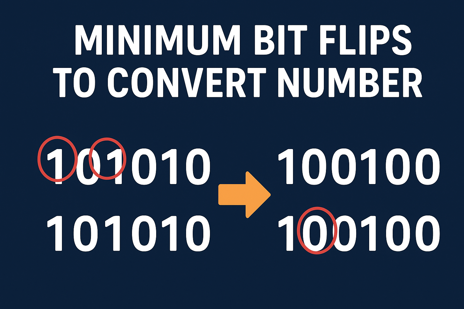
  • Minimum Bit Flips to Convert Number | Master Beginner’s Guide with LeetCode Solution 2026

    Minimum Bit Flips to Convert Number : When working with binary numbers in programming, you might encounter a problem where you need to find the minimum number of bit flips required to convert one number into another. This is a common interview and LeetCode problem that tests your understanding of bit manipulation.

    In this guide, we’ll explain the concept step-by-step, walk through examples, and provide a LeetCode-style C++ solution.

    What Does “Bit Flip” Mean?

    A bit flip means changing a 0 to 1 or a 1 to 0 in a number’s binary representation.

    Example:

    • Original bit: 0 → Flipped bit: 1
    • Original bit: 1 → Flipped bit: 0

    If you have two integers, finding the minimum bit flips means determining the positions where the bits differ.

    Minimum Bit Flips to Convert Number  leetcode solution
    Minimum Bit Flips to Convert Number leetcode solution

    Understanding the Problem

    Problem Statement:
    Given two integers start and goal, return the minimum number of bit flips required to convert start to goal.

    Example

    Input: start = 10, goal = 7
    Binary of 10 → 1010
    Binary of 7  → 0111
    

    Comparing bit by bit:

    1 0 1 0  
    0 1 1 1  
    ↑ ↑   ↑  
    Different bits at positions 1, 2, and 4 → 3 flips needed
    

    Approach

    1. Use XOR to identify different bits:
      • XOR (^) returns 1 for differing bits, 0 for same bits.
    2. Count set bits in the XOR result:
      • The number of 1s = the number of bit flips needed.

    Step-by-Step Example

    For start = 29 and goal = 15:

    1. XOR Operation: 29 (11101) 15 (01111) XOR → 10010
    2. Count set bits in 10010:
      There are 2 set bits → 2 flips needed.

    1. C++ Solution

    #include <iostream>
    using namespace std;
    
    int minBitFlips(int start, int goal) {
        int xorValue = start ^ goal; // Step 1: XOR to find differing bits
        int count = 0;
        while (xorValue > 0) {
            count += xorValue & 1;  // Step 2: Count set bits
            xorValue >>= 1;
        }
        return count;
    }
    
    int main() {
        int start = 10, goal = 7;
        cout << "Minimum Bit Flips: " << minBitFlips(start, goal) << endl;
        return 0;
    }
    

    ✅ Shortcut in C++ (GCC/Clang):

    return __builtin_popcount(start ^ goal);
    

    2. C Solution for Minimum Bit Flips to Convert Number

    #include <stdio.h>
    
    int minBitFlips(int start, int goal) {
        int xorValue = start ^ goal; // XOR to find differing bits
        int count = 0;
        while (xorValue > 0) {
            count += xorValue & 1;  // Count set bits
            xorValue >>= 1;
        }
        return count;
    }
    
    int main() {
        int start = 10, goal = 7;
        printf("Minimum Bit Flips: %d\n", minBitFlips(start, goal));
        return 0;
    }
    

    3. Java Solution for Minimum Bit Flips to Convert Number

    public class Main {
        public static int minBitFlips(int start, int goal) {
            int xorValue = start ^ goal; // XOR to find differing bits
            int count = 0;
            while (xorValue > 0) {
                count += xorValue & 1; // Count set bits
                xorValue >>= 1;
            }
            return count;
        }
    
        public static void main(String[] args) {
            int start = 10, goal = 7;
            System.out.println("Minimum Bit Flips: " + minBitFlips(start, goal));
        }
    }
    

    ✅ Shortcut in Java (Java 8+):

    return Integer.bitCount(start ^ goal);
    

    4. Python Solution for Minimum Bit Flips to Convert Number

    def min_bit_flips(start, goal):
        xor_value = start ^ goal  # XOR to find differing bits
        count = 0
        while xor_value > 0:
            count += xor_value & 1  # Count set bits
            xor_value >>= 1
        return count
    
    # Example
    start = 10
    goal = 7
    print("Minimum Bit Flips:", min_bit_flips(start, goal))
    

    ✅ Shortcut in Python:

    return bin(start ^ goal).count('1')
    

    Time Complexity for All Solutions

    • O(k), where k = number of bits in the integer.

    Real-World Applications

    • Error Detection & Correction in data transmission.
    • Cryptography and data encoding.
    • Digital Circuit Design optimization.

    Key Takeaways

    • Use XOR to detect differences in bits.
    • Count the number of 1s in the XOR result to get the flips.
    • This is a popular LeetCode problem for practicing bit manipulation.

    FAQ for Minimum Bit Flips to Convert Number

    Q1: Is this problem available on LeetCode?

    Yes, it’s a well-known LeetCode problem often asked in coding interviews.

    Q2: What’s the fastest approach?

    The XOR + count set bits method is the fastest and most memory-efficient.

    Q3: Can I solve this in one line in C++?

    Yes, using __builtin_popcount(start ^ goal) in GCC/Clang.
  • Master DHT11 to Firebase ESP8266 and ESP32 | Beginner’s Guide to Send Data & Display on Website (2026)

    Learn how to connect Wi-Fi, read Master DHT11 to Firebase ESP8266 and ESP32 Beginner’s Guide to Send Data & Display on Website (2025), and display temperature & humidity data live on your custom HTML/CSS/JS website. Learn how to read temperature & humidity from a DHT11 using ESP8266/ESP32, send it to Firebase Realtime Database over Wi-Fi, and display live readings on a custom HTML/CSS/JS website. Full code, wiring diagram, and SEO tips included.

    Master DHT11 to Firebase ESP8266 and ESP32

    Quick overview (What you’ll build for DHT11 to Firebase ESP8266 and ESP32 )

    1. ESP8266/ESP32 reads temperature & humidity from a DHT11 sensor.
    2. Device connects to your Wi-Fi and posts JSON data to Firebase Realtime Database.
    3. A simple web app (HTML/CSS/JS) reads the Firebase data and displays it live.
      This is a common workflow for hobby IoT dashboards. (Random Nerd Tutorials)

    Prerequisites of DHT11 to Firebase ESP8266 and ESP32

    • Hardware: ESP8266 NodeMCU (or ESP32), DHT11 sensor, jumper wires, breadboard, micro USB cable.
    • Software: Arduino IDE (or PlatformIO), DHT library (by Adafruit or other), WiFi and HTTP client libraries (built into ESP cores), Firebase Realtime Database (a Firebase project).
    • Basic familiarity with Arduino IDE and creating a Firebase project in the Firebase console. Helpful tutorials use these exact stacks. (Random Nerd Tutorials, Instructables)

    Hardware wiring (simple)

    • DHT11 VCC → 3.3V (or 5V depending on module; NodeMCU uses 3.3V recommended)
    • DHT11 GND → GND
    • DHT11 DATA → D2 (GPIO4) on NodeMCU (or any digital pin on ESP32)
    • If module has a pull-up resistor, fine; if not, add a 4.7k–10k pull-up between DATA and VCC.
      This wiring pattern is standard for NodeMCU+DHT setups. (Instructables, iotbyhvm.ooo)

    Step 1 : Create Firebase project & Realtime Database

    1. Go to [Firebase console] and create a new project.
    2. In “Build → Realtime Database” create a database and start in test mode for development (this allows reads/writes from the device). Important: test mode is insecure — switch to proper rules and auth before production.
    3. Note your database URL, it looks like https://your-project-id-default-rtdb.firebaseio.com/. You’ll use this as the base URL to POST JSON.
      (Using Realtime Database + direct REST writes or Firebase libraries is the common approach for IoT devices). (Random Nerd Tutorials)

    Security note: For production, secure your database with rules or use authenticated tokens. Tutorials often use test mode for beginners to simplify setup. (Random Nerd Tutorials)

    Step 2 : ESP code (NodeMCU / ESP8266 example using Arduino IDE)

    This example uses the DHT library + ESP8266HTTPClient to POST via Firebase REST API. Replace placeholders (SSID, PASSWORD, FIREBASE_URL) with your info.

    /* DHT11 -> Firebase (ESP8266) example
       Requires libraries:
       - DHT sensor library (by Adafruit) or similar
       - ESP8266WiFi (built-in)
       - ESP8266HTTPClient (built-in)
    */
    
    #include <ESP8266WiFi.h>
    #include <ESP8266HTTPClient.h>
    #include <ArduinoJson.h>    // optional but convenient
    #include <DHT.h>
    
    #define DHTPIN D2           // data pin (change if needed)
    #define DHTTYPE DHT11       // DHT 11
    DHT dht(DHTPIN, DHTTYPE);
    
    const char* ssid = "YOUR_WIFI_SSID";
    const char* password = "YOUR_WIFI_PASS";
    const char* firebaseUrl = "https://your-project-id-default-rtdb.firebaseio.com/"; // trailing slash
    
    unsigned long lastSend = 0;
    const unsigned long sendInterval = 15000; // 15s
    
    void setup() {
      Serial.begin(115200);
      delay(100);
      dht.begin();
      WiFi.begin(ssid, password);
      Serial.print("Connecting WiFi");
      while (WiFi.status() != WL_CONNECTED) {
        delay(500);
        Serial.print(".");
      }
      Serial.println("\nWiFi connected, IP: ");
      Serial.println(WiFi.localIP());
    }
    
    void loop() {
      if (millis() - lastSend < sendInterval) return;
      lastSend = millis();
    
      float h = dht.readHumidity();
      float t = dht.readTemperature();
    
      if (isnan(h) || isnan(t)) {
        Serial.println("Failed reading DHT sensor!");
        return;
      }
    
      // Build JSON
      String payload = "{";
      payload += "\"temperature\":" + String(t, 2) + ",";
      payload += "\"humidity\":" + String(h, 2) + ",";
      payload += "\"ts\":" + String(millis());
      payload += "}";
    
      // Firebase REST: POST to /readings.json to push a new node
      String url = String(firebaseUrl) + "readings.json"; // test mode (no auth)
      Serial.println("POST to: " + url);
      Serial.println(payload);
    
      if (WiFi.status() == WL_CONNECTED) {
        HTTPClient http;
        http.begin(url);
        http.addHeader("Content-Type", "application/json");
        int httpCode = http.POST(payload);
        if (httpCode > 0) {
          String resp = http.getString();
          Serial.printf("HTTP %d: %s\n", httpCode, resp.c_str());
        } else {
          Serial.printf("Failed, error: %s\n", http.errorToString(httpCode).c_str());
        }
        http.end();
      } else {
        Serial.println("WiFi not connected");
      }
    }
    

    Notes:

    • This uses the Realtime Database REST API (push to readings.json) — many community tutorials use the same method for simplicity. (How2Electronics, Instructables)
    • For ESP32, replace include/wifi classes accordingly and D2 pin selection may differ. See RandomNerdTutorials for ESP32 variants. (Random Nerd Tutorials)

    Step 3 : Verify data in Firebase console

    Open your Firebase Realtime Database in the console; you should see a /readings node with auto-generated keys and JSON objects containing temperature, humidity, and ts. This confirms successful writes. Many tutorials use this verify step. (Random Nerd Tutorials)

    Step 4 : Simple web app to display readings (HTML/CSS/JS)

    You can either:

    • Use Firebase Web SDK (recommended) to read Realtime Database easily and show live updates; or
    • Use REST calls from JS to pull latest data periodically.

    Below is a minimal Firebase Web SDK example (place in index.html). Replace the firebaseConfig object with your project config (found in Firebase console → Project settings → SDK setup):

    <!doctype html>
    <html>
    <head>
      <meta charset="utf-8">
      <meta name="description" content="Live DHT11 dashboard using Firebase Realtime Database">
      <meta name="viewport" content="width=device-width,initial-scale=1">
      <title>DHT11 Firebase Dashboard</title>
      <style>
        body{font-family:Arial,Helvetica,sans-serif;display:flex;flex-direction:column;align-items:center;padding:2rem;}
        .card{border-radius:8px;padding:1rem;box-shadow:0 6px 18px rgba(0,0,0,0.08);width:320px;text-align:center;}
        .big{font-size:2.4rem;font-weight:600;}
        .small{color:#666}
      </style>
    </head>
    <body>
      <div class="card">
        <div class="big" id="temp">-- °C</div>
        <div class="small">Temperature</div>
      </div>
      <div style="height:12px"></div>
      <div class="card">
        <div class="big" id="hum">-- %</div>
        <div class="small">Humidity</div>
      </div>
    
      <!-- Firebase SDK -->
      <script src="https://www.gstatic.com/firebasejs/9.22.0/firebase-app-compat.js"></script>
      <script src="https://www.gstatic.com/firebasejs/9.22.0/firebase-database-compat.js"></script>
      <script>
        // Replace with your Firebase config
        const firebaseConfig = {
          apiKey: "YOUR_API_KEY",
          authDomain: "YOUR_PROJECT.firebaseapp.com",
          databaseURL: "https://your-project-id-default-rtdb.firebaseio.com",
          projectId: "YOUR_PROJECT",
          storageBucket: "YOUR_PROJECT.appspot.com",
          messagingSenderId: "SENDER_ID",
          appId: "APP_ID"
        };
        firebase.initializeApp(firebaseConfig);
        const db = firebase.database();
    
        // Listen for last reading (assumes readings/child push used in the device)
        const readingsRef = db.ref('readings'); 
        // We'll query the last item:
        readingsRef.limitToLast(1).on('child_added', snapshot => {
          const data = snapshot.val();
          if (data) {
            document.getElementById('temp').textContent = (data.temperature || '--') + " °C";
            document.getElementById('hum').textContent = (data.humidity || '--') + " %";
          }
        });
      </script>
    </body>
    </html>
    

    Why this works: The Firebase Web SDK keeps a realtime socket to the DB and updates the DOM when new readings arrive. This is the same approach used in many Firebase IoT dashboards. (Random Nerd Tutorials)

    Common errors & troubleshooting ESP8266 and ESP32

    • Wi-Fi won’t connect: check SSID/password, check 3.3V vs 5V for modules.
    • DHT readings nan: ensure correct wiring and a short delay after dht.begin(). DHT11 is slow (max ~1Hz).
    • Firebase write errors (403): database rules might block unauthenticated writes — either open test mode (dev only) or implement auth. Tutorials warn about test mode. (Instructables, Arduino Forum)

    FAQ of DHT11 to Firebase

    Q: Do I need a Firebase paid plan?

    A: No — Firebase Realtime Database has a free tier sufficient for small hobby projects. For production and heavy write/read operations, consider billing & quotas. (Random Nerd Tutorials)


    Q: Can I use DHT22 instead of DHT11?

    A: Yes — DHT22 gives better accuracy and range; switch DHTTYPE and wiring as needed. Many guides use either sensor. (Random Nerd Tutorials)

    Q: Is it safe to keep DB in test mode?

    A: No — test mode is insecure. Use Firebase rules and authentication for production. (Random Nerd Tutorials)

    Sources & references (most useful tutorials / examples I consulted)

  • Master Hello World using Yocto | Build & Run a Linux Kernel Driver on BeagleBone Black (2026)

    Hello World using Yocto : Learn how to build a simple “Hello World” Linux kernel module from scratch using the Yocto Project for the BeagleBone Black. This step-by-step guide covers everything you need — from installing essential build tools, cloning the Yocto and meta-ti layers, creating a custom meta layer for your kernel module, writing the driver code, creating the recipe, to building and deploying the image on your BeagleBone Black device. Perfect for embedded Linux developers and beginners, this tutorial ensures you understand how to integrate and run out-of-tree kernel modules efficiently using Yocto’s powerful build system.

    What is Yocto?

    Yocto Project is an open-source collaboration project that helps developers create custom Linux-based systems for embedded devices. It provides tools, templates, and methods to build your own Linux distribution tailored to your hardware and software needs.

    Why use Yocto?

    • Custom Linux builds: You can create a Linux system optimized for your specific hardware (like BeagleBone Black, Raspberry Pi, etc.).
    • Reproducible builds: You can reproduce the exact same Linux image anytime.
    • Cross-compilation: It simplifies building software on your desktop machine for another target platform.
    • Scalability: Use it for small embedded devices or large, complex systems.
    • Community support: Backed by many companies and contributors in the embedded world.

    Key components of Yocto

    • BitBake: The build engine (like make but more powerful for embedded Linux).
    • Poky: The reference distribution and set of metadata recipes.
    • Recipes: Scripts that define how to build packages, kernels, and images.
    • Layers: Collections of recipes and configuration that can be added to customize the build.

    Who uses Yocto?

    • Embedded system developers building custom Linux for hardware like automotive infotainment, IoT devices, industrial controllers, and more.
    • Companies wanting to maintain full control over their embedded Linux stack.

    What is Poky?

    Poky is the reference build system and distribution provided by the Yocto Project. It’s basically a set of metadata, tools, and configurations that you use as a starting point to build your own custom embedded Linux images.

    Details:

    • Poky = Yocto Project reference system
      It includes the BitBake build tool plus a collection of recipes, configuration files, and classes that define how to build software packages, the Linux kernel, and the overall system image.
    • It’s a base for your custom Linux
      When you start a Yocto Project build, most tutorials and examples use Poky because it’s a complete and tested setup.
    • Contains layers like:
      • meta: core metadata layer with basic recipes and configurations
      • meta-poky: specific poky configurations and utilities
      • meta-yocto: essential recipes for a minimal embedded Linux distribution

    Why is Poky important?

    • It’s the default “reference distro” for Yocto, meaning it provides a working baseline system.
    • You can extend or modify Poky with additional layers to support your hardware and software requirements.
    • It helps you understand how the Yocto build system works before diving into more complex customizations.

    What is BitBake?

    BitBake is the build engine/tool used by the Yocto Project (and Poky) to compile and assemble software components into a complete Linux image for embedded systems.

    Details:

    • It’s like “make” on steroids but designed specifically for building embedded Linux systems.
    • BitBake reads special files called recipes (.bb files), which describe how to fetch, configure, compile, and package software.
    • It manages complex build tasks, dependencies, and executes them in the right order.
    • BitBake supports cross-compilation, so you can build software on your development machine for a different target device.
    • It also handles layers, configuration, and task scheduling.

    Why is BitBake important?

    • It automates the entire build process for embedded Linux, from downloading source code to creating a final flashable image.
    • It ensures reproducibility — builds can be repeated with the same results.
    • BitBake is highly extensible and can be customized with your own recipes.

    Install Yocto Prerequisites

    On your Ubuntu/Debian build machine:

    sudo apt update
    sudo apt install -y gawk wget git-core diffstat unzip texinfo \
      gcc build-essential chrpath socat cpio python3 python3-pip python3-pexpect \
      xz-utils debianutils iputils-ping python3-git python3-jinja2 \
      libegl1-mesa libsdl1.2-dev pylint3 xterm
    

    These are the official Yocto host dependencies.

    Download Yocto (Poky) and BeagleBone BSP Layer

    We’ll use the Yocto Kirkstone LTS release and meta-ti for TI boards like the BBB.

    mkdir ~/yocto-bbb
    cd ~/yocto-bbb
    
    # Poky (Yocto core)
    git clone -b kirkstone git://git.yoctoproject.org/poky
    
    # TI BSP layer (BeagleBone support)
    git clone -b kirkstone git://git.yoctoproject.org/meta-ti
    

    Set Up the Build Environment

    cd poky
    source oe-init-build-env
    

    This creates and moves you into a build/ directory.

    Add BeagleBone Black Layers

    bitbake-layers add-layer ../meta-ti
    

    Set the Machine to BeagleBone Black

    Edit conf/local.conf:

    MACHINE = "beaglebone"
    

    Create Your Custom Layer for the Driver

    cd ~/yocto-bbb
    bitbake-layers create-layer meta-hello
    bitbake-layers add-layer ../meta-hello
    

    Create the Hello World Kernel Module

    Directory Structure:

    meta-hello/
    └── recipes-kernel/
        └── hello-module/
            ├── files/
            │   ├── hello.c
            │   ├── Makefile
            │   └── COPYING
            └── hello-module_0.1.bb
    

    hello.c

    #include <linux/module.h>
    #include <linux/kernel.h>
    #include <linux/init.h>
    
    MODULE_LICENSE("GPL");
    MODULE_AUTHOR("Nish");
    MODULE_DESCRIPTION("Hello World Kernel Module for BeagleBone Black");
    
    static int __init hello_init(void)
    {
        printk(KERN_INFO "Hello, BeagleBone World!\n");
        return 0;
    }
    
    static void __exit hello_exit(void)
    {
        printk(KERN_INFO "Goodbye, BeagleBone World!\n");
    }
    
    module_init(hello_init);
    module_exit(hello_exit);
    

    Makefile

    obj-m := hello.o
    

    COPYING

    GNU GENERAL PUBLIC LICENSE
    Version 2, June 1991
    

    Get its checksum:

    md5sum COPYING
    

    hello-module_0.1.bb

    SUMMARY = "Hello World Kernel Module for BeagleBone Black"
    DESCRIPTION = "A simple kernel module built with Yocto for BBB"
    LICENSE = "GPL-2.0"
    LIC_FILES_CHKSUM = "file://COPYING;md5=<paste-md5-here>"
    
    SRC_URI = "file://hello.c \
               file://Makefile \
               file://COPYING"
    
    S = "${WORKDIR}"
    
    inherit module
    

    Include the Module in the Image

    Edit conf/local.conf:

    IMAGE_INSTALL_append = " kernel-module-hello"
    

    (Optional: Auto-load at boot)

    KERNEL_MODULE_AUTOLOAD += "hello"
    

    Build the Image

    cd ~/yocto-bbb/poky
    source oe-init-build-env
    bitbake core-image-minimal
    

    After the build completes, the image will be in:

    tmp/deploy/images/beaglebone/
    

    Flash to SD Card

    Insert your SD card and find its device name:

    lsblk
    

    Flash:

    sudo dd if=tmp/deploy/images/beaglebone/core-image-minimal-beaglebone.wic of=/dev/sdX bs=4M status=progress
    sync
    

    Boot BeagleBone Black

    • Insert SD card into BBB
    • Power it up (hold BOOT button if needed to boot from SD)

    Test the Module on BBB

    # Check if auto-loaded
    lsmod | grep hello
    
    # If not, load manually
    sudo modprobe hello
    
    # Check kernel logs
    dmesg | tail
    
    # Remove module
    sudo rmmod hello
    dmesg | tail
    

    Expected output:

    [   15.123456] Hello, BeagleBone World!
    [   20.654321] Goodbye, BeagleBone World!
    

    ✅ You’ve successfully built, packaged, and run a Hello World Linux kernel driver on BeagleBone Black using Yocto!

    Frequently asked questions (FAQ) | Hello World using Yocto

    1. What is Yocto and why use it for building kernel modules?

    Yocto is a powerful open-source build system for creating custom Linux distributions for embedded devices like BeagleBone Black. Using Yocto to build kernel modules ensures reproducible builds, automatic packaging, and easy integration into your custom image.

    2. How do I install the necessary host tools for Yocto?

    On Ubuntu/Debian, run:

    sudo apt install gawk wget git-core diffstat unzip texinfo gcc build-essential chrpath socat cpio python3 python3-pip python3-pexpect xz-utils
    

    This installs all required tools and dependencies for Yocto to build properly.

    3. Why do I need to clone both ‘poky’ and ‘meta-ti’ repositories?

    ‘poky’ is the main Yocto reference distribution containing BitBake and core layers. ‘meta-ti’ provides board support packages (BSP) and recipes specific to Texas Instruments devices like the BeagleBone Black.

    4. How do I add my own kernel module to the Yocto build?

    Create a custom meta layer (meta-hello), add your kernel module source and recipe inside it, then add this layer to your build using bitbake-layers add-layer. Finally, append your kernel module package to IMAGE_INSTALL in local.conf.

    5. What does inherit module do in the recipe?

    It tells Yocto that this recipe builds a kernel module, so it sets up the proper build environment, compiles the code against the kernel headers, and packages the module correctly.

    6. How do I ensure my module loads automatically on boot?

    Set the variable KERNEL_MODULE_AUTOLOAD += "hello" in your local.conf or image recipe. Yocto will then create the necessary config files to load your module during system startup.

    7. What if my module doesn’t load or I get errors?

    • Check kernel logs with dmesg to see error messages.
    • Verify that the module is actually included in your image (IMAGE_INSTALL).
    • Make sure the kernel version on your target matches the one you built the module for.
    • Use modprobe instead of insmod to handle dependencies.

    8. How do I flash the Yocto-built image to the BeagleBone Black?

    Use dd to write the .wic image to your SD card:

    sudo dd if=core-image-minimal-beaglebone.wic of=/dev/sdX bs=4M status=progress && sync
    

    Replace /dev/sdX with your actual SD card device.

    9. Can I build and test the kernel module without building the entire image?

    Yes! You can build just the module by running:

    bitbake hello-module
    

    Then manually copy the resulting .ko file to the target and load it with insmod or modprobe.

    10. Where can I find more resources to learn Yocto and kernel module development?

  • Hello World Kernel Driver, Master How to Write in Linux (Step-by-Step Guide 2026)

    Hello World Kernel Driver : If you are starting your journey into Linux device driver development, writing a simple Hello World kernel module is the perfect first step. In this tutorial, we will walk you through creating, compiling, and loading a kernel driver in Linux — all in a beginner-friendly way.

    Learn how to write your first Hello World Linux kernel driver with this step-by-step tutorial for beginners. This complete Linux kernel module development guide covers everything from setting up your environment to compiling and loading a kernel module. You will understand the basics of Linux device driver development, including how to create a simple printk() output in the kernel log, use module_init and module_exit functions, and build your driver using a Makefile. Whether you’re new to kernel programming in Linux or want to get started with embedded systems and operating system internals, this beginner-friendly guide will help you master the fundamentals of writing and running your own kernel modules. Perfect for students, hobbyists, and professionals looking to learn Linux driver programming from scratch.

    What is a Hello World kernel module in Linux ?

    A Linux kernel module (LKM) is a piece of code that can be loaded and unloaded into the Linux kernel at runtime. This allows you to add new functionalities, such as hardware drivers, without rebuilding the entire kernel.

    A “Hello World” kernel driver is the simplest example — it just prints a message when loaded and unloaded.

    Prerequisites of Hello World Kernel Driver

    Before writing your kernel module, make sure you have:

    • A Linux system (Ubuntu, Debian, Fedora, or similar)
    • Basic knowledge of C programming
    • Installed kernel headers and build tools

    For Ubuntu/Debian-based systems, run:

    sudo apt update
    sudo apt install build-essential linux-headers-$(uname -r)
    

    Step 1: Create the Source Code

    Create a new directory for your driver and a file named hello.c:

    mkdir hello_driver
    cd hello_driver
    nano hello.c

    Paste the following code:

    #include <linux/init.h>     
    #include <linux/module.h>   
    #include <linux/kernel.h>   
    
    MODULE_LICENSE("GPL");
    MODULE_AUTHOR("Your Name");
    MODULE_DESCRIPTION("A Simple Hello World Linux Kernel Module");
    MODULE_VERSION("1.0");
    
    static int __init hello_init(void) {
        printk(KERN_INFO "Hello, World! Kernel module loaded.\n");
        return 0;
    }
    
    static void __exit hello_exit(void) {
        printk(KERN_INFO "Goodbye, World! Kernel module unloaded.\n");
    }
    
    module_init(hello_init);
    module_exit(hello_exit);

    Explanation:

    • printk() prints messages to the kernel log (viewable with dmesg).
    • module_init() specifies the function to run when the module loads.
    • module_exit() specifies the function to run when the module unloads.

    Step 2: Create the Makefile

    The Makefile tells the Linux kernel build system how to compile your module.

    Create a file named Makefile:

    obj-m += hello.o
    
    all:
    	make -C /lib/modules/$(shell uname -r)/build M=$(PWD) modules
    
    clean:
    	make -C /lib/modules/$(shell uname -r)/build M=$(PWD) clean
    

    Step 3: Compile the Kernel Module

    Run:

    make

    If successful, you will see a new file called hello.ko — this is your compiled kernel driver.

    Step 4: Load the Module

    To load your driver into the kernel:

    sudo insmod hello.ko

    Check the kernel log:

    dmesg | tail

    You should see:

    Hello, World! Kernel module loaded.

    Step 5: Unload the Module

    When you want to remove the module:

    sudo rmmod hello

    Check the log again:

    dmesg | tail

    Output:

    Goodbye, World! Kernel module unloaded.

    Step 6: Clean Up

    To remove build files:

    make clean

    Final Thoughts

    You’ve just created your first Hello World kernel driver in Linux! This small example lays the foundation for developing more advanced Linux device drivers. From here, you can explore working with hardware, file operations, and different driver types (character, block, and network drivers)

    Frequently Asked Questions (FAQ) | Hello World Linux Kernel Driver

    1. What is a Hello World Kernel Driver ?

    A Linux kernel driver, also called a kernel module, is a piece of code that runs in the kernel space of the Linux operating system. It allows you to add functionalities like hardware control, system calls, or device communication without rebuilding the entire kernel.

    2. What is the purpose of a Hello World kernel module?

    The Hello World kernel module is the simplest example used to demonstrate Linux driver development. It helps beginners understand how to load and unload kernel modules, print messages to the kernel log, and use essential kernel functions.

    3. Do I need special hardware to write a Hello World Linux kernel driver?

    No. You can write and test a Hello World kernel module on any Linux system, including virtual machines, without special hardware.

    4. How do I compile a Hello World kernel module?

    You can compile a kernel module using a Makefile and the Linux kernel build system. The make command with the correct -C /lib/modules/$(uname -r)/build path will generate the .ko file (kernel object file) for your module.

    5. How do I load a kernel driver in Linux?

    You can load a compiled kernel driver using the insmod command, for example:
    sudo insmod hello.ko
    To confirm it loaded successfully, check the kernel log using:
    dmesg | tail

    6. How do I remove a kernel driver in Linux?

    You can remove a kernel driver using the rmmod command:
    sudo rmmod hello
    Then, verify it was removed by checking the kernel log with dmesg.

    7. Is it safe to experiment with kernel programming?

    Kernel programming requires caution because faulty code can crash the system. However, starting with a simple Hello World module in a test environment or virtual machine is safe and recommended for beginners.

    8. Can I use this Hello World driver on any Linux distribution?

    Yes, as long as your distribution provides the required kernel headers and build tools, you can compile and run the Hello World kernel module on Ubuntu, Debian, Fedora, Arch Linux, and more.
  • The Rising Importance of Rare Earth Materials in the Automotive Industry (2026 Update)

    Discover why rare earth materials like neodymium, dysprosium, and terbium are critical for the automotive industry in 2025. Learn how electric vehicle motors, car components, and global supply chains are being impacted by China’s export restrictions, and explore how countries like the U.S. and India are securing alternative sources to reduce dependency. Stay informed with the latest news and industry updates

    What Are Rare Earth Materials?

    Rare earth elements (REEs) comprise a set of 17 metallic elements including neodymium, dysprosium, and terbium. While they’re relatively abundant in the Earth’s crust, their extraction and refining are complex, which makes them strategically critical for modern industries.

    What Are Rare Earth Elements?

    REEs include scandium, yttrium, and the 15 lanthanides: lanthanum (La), cerium (Ce), praseodymium (Pr), neodymium (Nd), promethium (Pm), samarium (Sm), europium (Eu), gadolinium (Gd), terbium (Tb), dysprosium (Dy), holmium (Ho), erbium (Er), thulium (Tm), ytterbium (Yb), and lutetium (Lu).

    Based on their atomic weights, REEs are categorized into:

    • Light Rare Earth Elements (LREEs): Atomic numbers 57 to 63, including La, Ce, Pr, Nd, Pm, Sm, and Eu.
    • Heavy Rare Earth Elements (HREEs): Atomic numbers 64 to 71, including Gd, Tb, Dy, Ho, Er, Tm, Yb, and Lu.

    Although scandium and yttrium are lighter, they are grouped with the heavy REEs because of their similar chemical and physical traits.

    Characteristics and Sources of REEs

    Rare earth metals are known for their high density, elevated melting points, excellent electrical conductivity, and good thermal conductance. They typically carry a +3 oxidation state and have similar ionic sizes, contributing to their comparable properties.

    Common minerals rich in REEs include bastnaesite (a fluorocarbonate mineral found in carbonatites and related igneous rocks), xenotime (yttrium phosphate, often found in mineral sands), loparite (in alkaline igneous rocks), and monazite (a phosphate mineral). Some of these minerals contain trace amounts of radioactive thorium and uranium, although these are not essential components.

    Cerium is the most abundant rare earth element, with an abundance comparable to copper.

    Why Automotive Manufacturers Rely on Rare Earths

    Rare earth materials are integral in numerous vehicle components:

    • Electric and hybrid vehicle motors – Powerful permanent magnets made from neodymium, dysprosium, and terbium enable compact, efficient traction motors. (S&P Global, MagnetPlastic.com)
    • Everyday car parts – Even traditional gasoline cars use rare earth-based motors in components like windshield wipers, seat belt retractors, speakers, oil pumps, and sensors. (Reuters, Tradium)
    • Catalysts & polishing agents – Cerium and lanthanum are commonly used in catalytic converters and to polish glass or windshields. (Seltene Erden)

    Current Supply Chain Tensions

    New export restrictions from China—responsible for over 85–90% of rare earth refining and magnet production—have sent ripples across the global auto industry. (Reuters, The Verge, Wikipedia, The Wall Street Journal, Village Automotive Group, S&P Global)
    US automakers like Ford were forced to halt production temporarily due to material shortages. (CBS News, Reuters, S&P Global)
    In response, the U.S. and China agreed on a temporary easing of licenses for rare earth exports, giving manufacturers some breathing room. (Reuters, S&P Global)

    Meanwhile, India’s automobile sector has also sounded the alarm, urging government support for approving rare earth magnet imports to avoid production delays. (The Economic Times, The Times of India)

    Hot Off the Press: U.S. Efforts to Secure Supply

    • Domestic production ramp-up – MP Materials, operating the only rare earth mine in the U.S., reported a 119% surge in neodymium and praseodymium production, driven by heightened demand and government-backed deals. (Reuters)
    • Strategic supply deals – General Motors has signed a multi-year agreement with Noveon Magnetics—the only U.S. manufacturer of sintered NdFeB magnets—to secure domestic supply for its large SUVs and trucks. Deliveries began in July. (Reuters)

    Long-Term Outlook: Reducing Dependency on China

    • Regions like North America and India are exploring domestic extraction/refinement to build local supply chains. (S&P Global, Reuters)
    • Europe is experimenting with magnet-free motor technologies, such as externally-excited synchronous motors, which eliminate rare-earth magnets entirely. (S&P Global)

    Rare earth metals are known for their high density, elevated melting points, excellent electrical conductivity, and good thermal conductance. They typically carry a +3 oxidation state and have similar ionic sizes, contributing to their comparable properties.

    Want me to tailor this toward a specific market—like the Indian auto sector—or make it more data- or infographic-rich? Just say the word!

  • LIN in Automotive Interview: Master Complete Guide for 2026

    LIN in Automotive Interview is a common topic for engineers in the automotive industry. This guide explains the LIN protocol, its applications, common interview questions, and preparation tips to help you succeed.

    When it comes to automotive interviews, one topic that often surprises candidates is the Local Interconnect Network (LIN) protocol. While most engineers are familiar with CAN bus, LIN is equally important—especially for low-cost, non-critical systems in modern vehicles.

    In this guide, we’ll break down what LIN is, why it matters in automotive engineering, and how you can prepare for interview questions related to it.

    In this guide, we’ll break down what LIN is, why it matters in automotive engineering, and how you can prepare for interview questions related to it.

    What Is LIN in Automotive Interview

    The Local Interconnect Network (LIN) is a low-cost, single-wire, serial communication protocol used to connect various electronic control units (ECUs) and sensors in a vehicle.

    Unlike CAN (Controller Area Network), which handles critical, high-speed communication, LIN is designed for simpler, non-time-critical functions, such as:

    • Power window control
    • Climate control systems
    • Seat adjustment
    • Sunroof operation

    Key characteristics of LIN:

    • Operates at up to 20 Kbps
    • Works on a master-slave topology
    • Uses single wire + ground (saving wiring costs)
    • Includes synchronization and error detection mechanisms

    Why Is LIN Important in Automotive Interviews?

    LIN is widely used in automotive body electronics because it reduces wiring complexity and lowers manufacturing costs.

    In LIN in Automotive Interview, hiring managers test LIN knowledge to see if you:

    • Understand vehicle networking architectures
    • Can differentiate between LIN and CAN protocols
    • Know real-world use cases of LIN
    • Are familiar with message framing, checksum, and diagnostics

    Common LIN in Automotive Interview Questions

    Here are some typical questions you might face:

    1. What is the LIN protocol, and where is it used in vehicles?
      Tip: Highlight that it’s a low-speed, low-cost communication system for non-critical functions.
    2. Explain the difference between LIN and CAN bus.
      Tip: Compare speed, cost, complexity, and applications.
    3. Describe the LIN frame structure.
      Tip: Mention break field, sync field, identifier, data bytes, and checksum.
    4. What are LIN nodes, and how are they classified?
      Tip: Master node (controls communication) and slave nodes (respond to master requests).
    5. Give real-world examples of LIN implementation.
      Tip: Talk about wiper systems, mirror adjustment, and seat controls.

    How to Prepare for a LIN-Focused Automotive Interview

    1. Understand the Basics – Review how LIN works, frame structure, and advantages over other protocols.
    2. Compare with CAN – Be ready to explain why certain functions use LIN instead of CAN.
    3. Know the Applications – Mention specific automotive systems that rely on LIN.
    4. Brush Up on Standards – Familiarize yourself with ISO 17987 (LIN protocol standard).
    5. Practice Real Examples – If possible, look at a LIN bus log or use tools like a logic analyzer for hands-on understanding.

    Pro Tips for LIN in Automotive Interview Success

    • Use clear, structured answers—break down your response into definition, working, and application.
    • Relate your answers to practical automotive scenarios.
    • Show that you understand both hardware and software aspects of LIN.
    • If you have project experience with LIN, explain your role clearly.

    Conclusion

    In the evolving automotive industry, LIN remains a crucial protocol for reliable, cost-effective communication between vehicle subsystems. Whether you’re applying for an Automotive Engineer, Embedded Systems Engineer, or Vehicle Network Specialist role, understanding LIN can give you a competitive edge.

    Frequently Asked Questions (FAQ)

    1. What is this blog about?

    This blog focuses on delivering beginner-friendly and in-depth tutorials, tips, and real-world examples in the field of embedded systems, programming, and technology trends.

    2. Who can benefit from this blog?

    Students, fresh graduates, working professionals, and tech enthusiasts who want to improve their skills in embedded systems, C/C++, IoT, and related technologies will find this blog useful.

    3. Are the tutorials suitable for complete beginners?

    Yes. All tutorials are designed with step-by-step explanations, making them easy to follow even if you have no prior experience.

    4. Do I need any special tools to follow the projects?

    Some projects require specific hardware or software tools. Each tutorial clearly lists the tools and setup required before you begin.

    5. How often is the blog updated?

    New tutorials, guides, and project ideas are added regularly to ensure you always have fresh and relevant content.

    6. Can I request a specific topic or tutorial?

    Yes, you can share your topic requests via the contact form. If it aligns with the blog’s focus, it will be considered for future posts.
  • Master CAN Bus Interview Questions 2026

    CAN Bus Interview Questions : If you are preparing for an embedded systems or automotive interview, chances are you’ll face questions on CAN bus, a widely-used communication protocol in vehicles. This article simplifies CAN bus interview questions for beginners and helps you understand the key concepts, architecture, message handling, and real-world applications in a friendly tone.

    Whether you’re a student, fresher, or experienced developer brushing up for an interview, this guide is a great place to start.

    CAN Bus Interview Questions

    CAN Bus Interview Questions
    CAN Bus Interview Questions

    Basic Concepts

    1. What does CAN stand for in CAN bus?
    2. What is CAN bus and why is it used in automotive systems?
    3. Describe the basic architecture of a CAN bus system.
    4. What are the primary components of a CAN bus network?
    5. Explain the difference between a CAN node and a CAN message.

    Message Format and Communication

    1. Can you explain the message format used in CAN bus?
    2. What is the purpose of the CAN identifier field in a CAN message?
    3. Describe the difference between standard and extended CAN identifiers.
    4. How does CAN bus support prioritization of messages?
    5. Describe the process of arbitration in CAN bus communication.

    Data Transmission & Reliability

    1. How does CAN bus ensure message integrity and reliability?
    2. How does CAN bus handle message collisions?
    3. How does CAN bus handle error detection and error handling?
    4. What is bit stuffing, and why is it used in CAN bus communication?
    5. What is the maximum data transfer rate supported by CAN bus?

    Filtering, Speed, and Configuration

    1. Can you explain the concept of message filtering in CAN bus?
    2. How does CAN bus handle communication between nodes with different bit rates?
    3. How does CAN bus support both high-speed and low-speed communication within a vehicle?
    4. What factors should be considered when designing a CAN bus network?

    Hardware & Physical Layer

    1. Explain the significance of termination resistors in a CAN bus network.

    Applications & Real-World Use Cases

    1. What are the advantages of using CAN bus over other communication protocols in automotive applications?
    2. What are the advantages of using CAN bus in automotive applications?
    3. Describe a scenario where you would choose CAN bus over other communication protocols for a specific application.
    4. How does CAN bus contribute to the overall reliability and safety of automotive systems?
    5. Describe a scenario where you encountered a communication issue on a CAN bus and how you resolved it.

    Suggested Additional Questions (Optional for Advanced Interviews)

    1. What is the function of ACK slot in CAN message frame?
    2. What happens if both nodes on a CAN bus transmit messages simultaneously with the same priority?
    3. What tools can be used to debug or monitor CAN bus activity?
    4. Can you explain the role of CAN transceivers?
    5. What’s the difference between CAN, LIN, and FlexRay protocols?

    Frequently Asked Questions | CAN Bus Interview Questions

    1.What is the CAN bus used for?

    Answer: CAN (Controller Area Network) is used for communication between multiple electronic control units (ECUs) in vehicles and other embedded systems without needing a central host. It ensures fast, reliable, and real-time data exchange.

    2.Is knowledge of CAN protocol important for embedded system engineers?

    Answer: Yes. CAN is widely used in automotive and industrial systems, so understanding it is essential for embedded developers working with microcontrollers, ECUs, or automation.

    3.What are the most common topics asked in CAN bus interviews?

    Answer: Key topics include:

    • CAN architecture
    • Message format and identifiers
    • Arbitration and prioritization
    • Bit timing and error handling
    • Termination resistors and filtering

    4.What’s the difference between standard and extended CAN identifiers?

    Answer: Standard identifiers are 11-bit long, while extended identifiers are 29-bit long, offering more unique message IDs and supporting complex systems.

    5.How can I prepare for CAN bus interviews?

    Answer:

    • Understand how CAN works at both physical and protocol layers
    • Study message structure, arbitration, and filtering
    • Practice interpreting CAN frames using tools like CANalyzer, PCAN View, or BusMaster
    • Review real-world issues and troubleshooting scenarios

    6.Is CAN bus only used in automotive systems?

    Answer: No. While it started in automotive, it’s also used in industrial automation, robotics, aerospace, and medical devices due to its robustness and fault tolerance.

    7.What tools are used for working with CAN bus?

    Answer: Common tools include:

    • CANalyzer
    • CANoe
    • PCAN View
    • BusMaster (open-source)
    • Logic analyzers with CAN decoders

    8.How can I explain a real-world CAN issue in an interview?

    Answer: Be honest. For example, explain a scenario where a node failed due to missing termination or noise interference, how you diagnosed it using a CAN tool, and how you fixed it.