An audio interface is a hardware component that allows a computer, microcontroller, or embedded system to send and receive digital audio data. It acts as a bridge between digital systems and audio hardware, such as microphones, speakers, amplifiers, and audio codecs.
In simple terms, an audio interface defines how audio samples are transferred, synchronized, and formatted between a processor (SoC, MCU, CPU) and an audio codec or peripheral.
What is Embedded Audio Hardware?
Embedded audio hardware is the physical circuitry and components that:
- Capture sound (from microphones)
- Process sound (digitally or analog)
- Store / transfer audio data
- Play sound (through speakers or headphones)
It works together with embedded software + audio drivers + audio frameworks (ALSA, I2S, etc.).
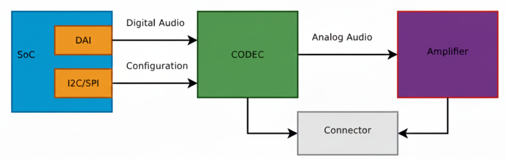
This diagram shows a typical embedded Linux / SoC audio playback architecture exactly the kind of pipeline you deal with in ALSA, QNX audio, codec drivers, and board bring-up.
Let’s break it block by block, signal by signal, and then connect it to real software components you use.
SoC (System on Chip)
The SoC is the brain of the system (Qualcomm, TI, NXP, STM32MP, etc.).
Inside the SoC, two important blocks are shown:
DAI (Digital Audio Interface)
This block is responsible for sending and receiving digital audio samples.
Typical interfaces:
- I2S
- TDM
- PCM
- DSP_A / DSP_B
What flows here?
- Raw PCM samples
- Example: 16-bit / 24-bit / 32-bit audio
- Sample rates: 44.1 kHz, 48 kHz, 96 kHz
Signals on the wire:
- BCLK (Bit clock)
- LRCLK / FS (Frame sync)
- DATA
This is high-speed, real-time audio data
I2C / SPI (Control Interface)
This is NOT audio data.
Used only for:
- Configuring the codec
- Setting volume
- Power control
- Selecting input/output paths
- Muting, unmuting
- Clocking modes
Example operations:
- Set DAC sample rate
- Enable headphone output
- Set gain = +6 dB
- Power up analog blocks
This is low-speed control, not streaming audio.
Digital Audio Path (SoC → CODEC)
The arrow labeled “Digital Audio” represents:
SoC DAI ──(I2S/TDM/PCM)──> CODEC
✔ Audio is still digital
✔ No voltage amplification
✔ No sound yet
This is where:
- ALSA PCM writes happen
- DMA transfers audio buffers
- Timing is critical
In ALSA terms:
- CPU DAI ↔ Codec DAI
- Defined in ASoC machine driver
- Linked using
snd_soc_dai_link
CODEC (Most Important Block)
The CODEC (Coder–Decoder) is the heart of audio hardware.
What the CODEC does:
- DAC: Digital → Analog (playback)
- ADC: Analog → Digital (capture)
- Filtering
- Mixing
- Volume control
- Clock management
Inputs:
- Digital audio (I2S/TDM)
- Control commands (I2C/SPI)
Outputs:
- Analog audio signals (line-level)
Important:
The codec output is NOT strong enough to drive speakers
That’s why the next block exists.
Analog Audio Path (CODEC → Amplifier)
The arrow labeled “Analog Audio” means:
- Audio is now continuous voltage
- Typical level: ~1 Vrms (line level)
- Sensitive to noise, grounding, layout
Signals here:
- Left / Right analog outputs
- Differential or single-ended
Amplifier
The Amplifier increases signal power so it can:
- Drive speakers
- Drive headphones
- Overcome impedance
Amplifier types:
- Class D (most common in embedded)
- Class AB
- Headphone amps
What it does:
- Voltage amplification
- Current amplification
- Power delivery
Example:
- Codec output: 1V
- Amplifier output: 5–12V swing (speaker)
Connector (Speaker / Headphone Jack)
The Connector is the physical output:
- Speaker connector
- 3.5mm headphone jack
- Line-out
- Automotive speaker terminals
Why shown separately?
Because:
- Board routing matters
- ESD protection is added
- Jack detection may exist
- Multiple outputs can be routed
Full Signal Flow (End-to-End)
Playback path:
Application (aplay / media app)
        ↓
ALSA PCM
        ↓
CPU DAI (SoC)
        ↓  [Digital Audio: I2S/TDM]
CODEC (DAC)
        ↓  [Analog Audio]
Amplifier
        ↓
Speaker / Headphones
Software Mapping (Very Important)
In Linux ALSA ASoC:
| Hardware Block | Software Component |
|---|---|
| SoC DAI | CPU DAI driver |
| CODEC | Codec driver |
| I2C/SPI | Regmap |
| Connections | Machine driver |
| User app | aplay, arecord |
Why WAV is Used for Testing
- WAV = raw PCM
- No decoding needed
- Direct match to DAI data
- Perfect for testing this pipeline
MP3/AAC would require:
- Decoder
- Extra CPU
- More variables
Big Picture Audio Hardware Block Diagram
Microphone
   ↓
[ Analog Front End ]
   ↓
ADC  →  SoC / MCU  →  DAC
   ↑        ↓        ↓
 Codec   DSP / CPU  Amplifier
                         ↓
                      Speaker
Let’s explain each block in detail.
Audio Input Hardware (Sound Capture)
Microphone
Converts sound waves → electrical signals
Types:
- Electret Condenser Mic (analog output)
- MEMS Mic
- Analog MEMS
- Digital MEMS (PDM / I2S output)
Key parameters:
- Sensitivity (dBV/Pa)
- Signal-to-noise ratio (SNR)
- Directionality (Omni / Uni-directional)
Analog Front End (AFE)
Before audio reaches the ADC, it must be conditioned.
AFE includes:
- Pre-amplifier (boosts weak mic signals)
- Biasing circuit (for electret mics)
- Low-pass filter (anti-aliasing)
- Noise filtering
Without AFE, captured audio will be noisy or distorted.
Audio Codec (Heart of Audio Hardware)
What is an Audio Codec?
A codec = Coder + Decoder
It usually integrates:
- ADC (Analog → Digital)
- DAC (Digital → Analog)
- Mixers, volume control, mute
- Power management
Examples:
- TLV320 series (TI)
- PCM5102, PCM1808
- WM8960
- Realtek codecs
Why Codec Is Important
- MCU/SoC cannot directly handle analog audio
- Codec ensures:
- Correct sampling
- Bit depth
- Clean audio conversion
Digital Audio Interfaces (SoC ↔ Codec)
Audio data moves digitally between SoC and codec.
I2S (Most Common)
Used for PCM audio.
Signals:
- BCLK (Bit Clock)
- LRCLK / WS (Left-Right clock)
- DATA
- MCLK (optional)
SoC  ←→  Codec
 I2S     I2S
Other Audio Interfaces
- PCM/TDM – multi-channel audio (automotive, pro audio)
- PDM – digital microphone interface
- SPDIF – consumer audio
- AC97 / HDA – PC-class audio
Audio Processing Hardware
MCU / SoC
Processes audio samples.
Responsibilities:
- Buffer management
- DMA handling
- Audio routing
- Running DSP algorithms
Examples:
- BeagleBone (AM335x)
- STM32F4/F7/H7
- ESP32
- Qualcomm SoCs
DSP (Optional but Powerful)
Dedicated processor for:
- Noise cancellation
- Echo cancellation
- Equalizer
- Compression
In many SoCs, DSP is integrated.
Audio Output Hardware (Sound Playback)
DAC
Converts digital PCM samples → analog waveform
Parameters:
- Resolution (16-bit / 24-bit)
- Sampling rate
- Dynamic range
Often integrated inside codec.
Audio Power Amplifier
Boosts low-level analog signal to drive speakers.
Examples:
- LM386 (you’ve used this)
- TPA3116
- Class-D amplifiers
Why needed?
- Codec output ≈ millivolts
- Speaker needs watts
Speaker / Headphones
Final sound-producing component.
Considerations:
- Impedance (4Ω, 8Ω)
- Power rating
- Mono vs stereo
Clocking Hardware (Very Important)
Audio hardware needs precise clocks.
Sources:
- External crystal
- SoC PLL
- Codec internal PLL
Clock affects:
- Sampling accuracy
- Audio quality
- Jitter
Power Management in Audio Hardware
Audio is sensitive to power noise.
Hardware includes:
- Separate analog & digital power rails
- LDOs
- Ground separation (AGND / DGND)
Bad power = hiss, pop, distortion.
Real Embedded Example (BeagleBone + Codec)
Mic → AFE → Codec ADC
               ↓
           I2S Bus
               ↓
        AM335x (ALSA)
               ↓
           I2S Bus
               ↓
           Codec DAC
               ↓
          LM386 Amp
               ↓
            Speaker
Software controls:
- ALSA drivers
- Device Tree
- Mixer settings
Common Embedded Audio Hardware Issues
- No sound → clock misconfiguration
- Distorted audio → wrong gain
- Noise → poor grounding
- Channel swap → LRCLK mismatch
- Crackling → buffer underrun
Summary
| Block | Purpose |
|---|---|
| Microphone | Capture sound |
| AFE | Condition analog signal |
| ADC | Convert to digital |
| Codec | Audio conversion + control |
| I2S/PCM | Transfer digital audio |
| SoC/DSP | Process audio |
| DAC | Convert to analog |
| Amplifier | Boost signal |
| Speaker | Play sound |
What is an Audio CODEC?
Codec = ADC + DAC + mixers + clocks + controls
CODEC = COder + DECoder
An audio codec is a single chip that can:
- Record sound → convert analog sound into digital data
- Play sound → convert digital data back into analog sound
It acts as a bridge between the real (analog) world and the digital world.
Controlled via:
- I2C / SPI → registers
- I2S / TDM → audio data
Why do we need a CODEC?
Microcontrollers / SoCs cannot understand analog voltages directly.
- Microphone → gives analog voltage
- Processor → understands digital numbers
- Speaker → needs analog voltage
So we need a translator → that’s the CODEC.
Inside a CODEC: ADC + DAC
A codec internally contains:
ADC (Analog to Digital Converter)
- Takes analog voltage (from mic/line-in)
- Converts it into digital samples
- Used during audio capture / recording
DAC (Digital to Analog Converter)
- Takes digital samples
- Converts them into analog voltage
- Used during audio playback
Both ADC and DAC are inside one chip → called an Audio CODEC
What exactly does a CODEC do?
Recording path
Microphone → Analog voltage → ADC → Digital samples → SoC
Playback path
SoC → Digital samples → DAC → Analog voltage → Speaker / Amplifier
How does a CODEC talk to the SoC? (DAI)
CODECs don’t send data randomly.
They use a Digital Audio Interface (DAI).
DAI is a synchronous serial interface (everything happens on clock edges).
Common DAI standards:
- I²S
- PCM
- TDM
PCM / I²S Interface Basics
The 2 Main Clocks
Bit Clock (BCLK / BCK)
- Ticks once per bit
- Controls bit-by-bit transfer
Frame Clock (LRCLK / FSCLK / WCLK)
- Ticks once per audio sample
- Indicates Left / Right channel
- Its frequency = Sample Rate (Fs)
Example:
- Fs = 48 kHz → 48,000 samples per second
Relationship Between Clocks
Formula:
BCLK = FS × Number_of_Channels × Bit_Depth
Example:
- Sample Rate (Fs) = 48 kHz
- Channels = 2 (Stereo)
- Bit depth = 16 bits
BCLK = 48,000 × 2 × 16 = 1.536 MHz
BCLK must run much faster than LRCLK.
Data Lines (Audio Data)
Along with clocks, we have data lines:
- Carry the actual audio bits
- Usually called:
SDATA,DSDATA,ASDATA
Important points:
- One data line can carry two channels (Left + Right)
- Some codecs have multiple data lines:
- One per channel pair
- Useful for multi-channel audio
Multiple DAI Interfaces
Some codecs support:
- Separate DAI for input (ADC)
- Separate DAI for output (DAC)
This allows:
- Different clocks
- Different sample rates
- Independent routing
Real Example: AD1937 CODEC
Capabilities
- 8 DAC channels → 4 stereo output pairs
- 4 ADC channels → 2 stereo input pairs
Playback (DAC side)
- Clocks:
ABCLK→ Bit clockALRCLK→ Frame clock
- Data lines:
ASDATA[1–2]→ 2 output data lines
Capture (ADC side)
- Clocks:
DBCLKDLRCLK
- Data lines:
DSDATA[1–4]→ 4 input data lines
Perfect for multi-channel professional audio systems
Control Interface (Configuration Bus)
Audio data ≠ configuration.
CODECs use a separate control bus to:
- Set volume
- Select sample rate
- Enable ADC/DAC
- Configure routing
Common control buses:
- I²C
- SPI
Audio flows on DAI, configuration happens on I²C/SPI.
What is MCLK? (Master Clock)
MCLK = System Clock for CODEC
- Required for internal codec operation
- Feeds internal DSP, ADC, DAC
How is MCLK provided?
- By SoC clock output
- By external crystal oscillator
- Sometimes derived from BCLK or LRCLK
Is MCLK Always Required?
- Usually yes
- Sometimes optional
Some codecs:
- Can run using BCLK or LRCLK
- Useful for simple systems
But:
- High-quality codecs usually require MCLK
MCLK Relationship
MCLK is usually a multiple of Fs:
Common values:
- 256 × Fs
- 384 × Fs
- 512 × Fs
Example:
- Fs = 48 kHz
- MCLK = 48k × 256 = 12.288 MHz
Big Picture Summary
Microphone → ADC → PCM/I²S → SoC → PCM/I²S → DAC → Speaker
                ↑           ↑
              MCLK        BCLK, LRCLK
SoC Audio Digital Interface (DAI)
What is Left-Justified (LJ) Audio Digital Format?
Left-Justified is a digital audio data format used to transfer audio samples between a codec and a SoC/DSP over serial audio interfaces like:
- I²S
- TDM
- PCM interfaces
It defines how audio bits are aligned with the clock signals.
The 3 Important Audio Signals (Recap)
In any digital audio interface, you’ll see:
| Signal | Meaning |
|---|---|
| BCLK | Bit Clock – clocks each bit |
| LRCLK / WS | Left-Right Clock (Word Select) |
| DATA | Actual audio sample bits |
Left-Justified format describes when DATA starts relative to LRCLK.
Left-Justified Format – Core Idea
The MSB (Most Significant Bit) of the audio sample appears immediately after the LRCLK transition.
Key Rule:
- No delay
- MSB is aligned with the LRCLK edge
- Data is “left-aligned” in the word frame
Timing Diagram (Conceptual)
LRCLK:  |____ LEFT ____|____ RIGHT ____|
            ↑                ↑
           MSB              MSB
BCLK :  |‾|_|‾|_|‾|_|‾|_|‾|_|‾|_|
DATA :  [MSB ........ LSB][MSB .... LSB]
As soon as LRCLK changes:
- Data starts immediately
- First bit = MSB
Example: 16-bit Audio Sample
Assume:
- Sample size = 16 bits
- Left channel sample =
0x5A3C
Bit Transmission (Left Channel)
LRCLK = 0  → LEFT channel
DATA   = 0 1 0 1 1 0 1 0 0 0 1 1 1 1 0 0
          ↑
         MSB (no delay!)
Left-Justified vs I²S (Very Important Interview Point)
| Feature | Left-Justified | I²S |
|---|---|---|
| MSB position | Immediately after LRCLK edge | 1 BCLK delay |
| Alignment | Left aligned | Delayed |
| Simplicity | Simple | Slightly complex |
| Codec support | Older & simple codecs | Most modern codecs |
This 1-bit delay is the ONLY difference — but it breaks audio if misconfigured.
Why is it Called “Left-Justified”?
Because:
- Audio data is pushed to the left side of the word frame
- No padding before MSB
- Extra unused bits (if any) come after LSB
Example (24-bit sample on 32-bit frame):
[ MSB .... LSB ][ 0 0 0 0 0 0 0 0 ]
Where is Left-Justified Used?
Common in:
- Audio codecs (TLV320, PCM series)
- Simple DAC/ADC interfaces
- Embedded SoCs during codec bring-up
- Some QNX / ALSA hardware configs
You’ll often see it as:
LEFT_J
LEFT_JUSTIFIED
LJ
ALSA / Embedded Perspective (Real World)
In ALSA, Left-Justified is configured using:
- DAI format flags
- Example:
SND_SOC_DAIFMT_LEFT_J
If:
- Codec = Left-Justified
- SoC = I²S
Audio will be distorted or silent
Simple One-Line Definition (Interview Ready)
Left-Justified audio format is a digital audio data format where the MSB of the sample appears immediately after the LRCLK transition, with no bit delay.
What is Right-Justified (RJ) Audio Digital Format?
Right-Justified is a digital audio data alignment format used to transfer audio samples between:
- Codec ↔ SoC / DSP
- Over interfaces like I²S, PCM, TDM
It defines how audio bits are aligned with the LRCLK (Word Select) signal.
Core Idea (Very Important)
In Right-Justified format, the LSB (Least Significant Bit) of the audio sample is aligned with the end of the LRCLK period.
Meaning:
- Data is right-aligned
- MSB position depends on sample width
Signals Involved
| Signal | Role |
|---|---|
| BCLK | Clocks each bit |
| LRCLK / WS | Selects Left or Right channel |
| DATA | Audio sample bits |
Right-Justified format defines where the LSB appears relative to LRCLK.
Timing Concept (Simple View)
LRCLK:  |____ LEFT ____|____ RIGHT ____|
                     ↑                ↑
                    LSB              LSB

BCLK :  |‾|_|‾|_|‾|_|‾|_|‾|_|‾|_|
DATA :  [MSB .... LSB][MSB .... LSB]
The last bit before LRCLK changes is always LSB.
Example: 16-bit Audio Sample
Assume:
- Sample size = 16 bits
- Frame size = 32 bits
Left Channel Transmission
[ 0 0 0 0 0 0 0 0 | MSB .... LSB ]
                    ↑           ↑
                  starts      aligned
Padding bits come before MSB
Sample ends exactly at LRCLK edge
Why “Right-Justified”?
Because:
- Audio data is aligned to the right side of the frame
- Extra unused bits are placed before MSB
- LSB touches the LRCLK boundary
Right-Justified vs Left-Justified vs I²S
| Feature | Left-Justified | Right-Justified | I²S |
|---|---|---|---|
| MSB alignment | Immediately after LRCLK | Variable | 1 BCLK delay |
| LSB alignment | Variable | At LRCLK edge | Fixed |
| Padding bits | After LSB | Before MSB | After LSB |
| Common usage | Some codecs | Legacy codecs | Most modern systems |
Important Embedded Detail
In Right-Justified, the SoC must know sample width:
- 16-bit
- 20-bit
- 24-bit
- If sample width mismatches:
- Audio distortion
- Shifted samples
- Noise / silence
This is why RJ is more error-prone than LJ or I²S.
ALSA / Driver Perspective
In ALSA SoC drivers, Right-Justified is selected using:
SND_SOC_DAIFMT_RIGHT_J
Typical usage:
- Old DACs / ADCs
- Simple PCM audio paths
- Some automotive codecs
One-Line Interview Definition
Right-Justified audio format aligns the LSB of each audio sample with the LRCLK edge, while MSB position depends on the sample width.
Quick Memory Trick
- Left-Justified → MSB touches LRCLK
- Right-Justified → LSB touches LRCLK
- I²S → MSB delayed by 1 BCLK
What is I2S (Inter-IC Sound)?
I2S (Inter-IC Sound) is a digital audio communication protocol used to transfer audio data between chips such as a processor, audio codec, DAC, or ADC.
Key Points of I2S
- Designed specifically for digital audio
- Transfers PCM (Pulse Code Modulation) audio data
- Commonly used in embedded systems, SoCs, and audio boards
- Simple and easy to implement
I2S Signals
I2S uses three or four lines:
- BCLK (Bit Clock): Clocks each audio bit
- LRCLK / WS (Word Select): Selects Left or Right audio channel
- SD (Serial Data): Carries audio sample data
- MCLK (Optional): Master clock for codec timing
I2S Features
- Supports stereo audio (Left & Right)
- Fixed channel structure
- Low latency
- Ideal for headphones, speakers, microphones
Where I2S is Used
- Audio codecs (PCM, WM, TLV series)
- Embedded Linux audio (ALSA)
- Microcontrollers and DSPs
- Music players and voice applications
What is TDM (Time Division Multiplexing)?
TDM (Time Division Multiplexing) is a digital audio interface that allows multiple audio channels to be transmitted over a single data line by assigning each channel a time slot.
Key Points of TDM
- Supports multi-channel audio
- Uses time slots instead of separate data lines
- Highly scalable and efficient
- Common in professional and automotive audio systems
TDM Signals
TDM typically uses:
- BCLK (Bit Clock): Drives bit transmission
- FS / SYNC (Frame Sync): Marks start of a frame
- SD (Serial Data): Carries data for all channels
TDM Features
- Supports 4, 8, 16, or more channels
- Better bandwidth utilization
- Reduces pin count on SoCs
- Ideal for surround sound and voice systems
Where TDM is Used
- Automotive infotainment systems
- Multi-microphone arrays
- Professional audio mixers
- Advanced SoC audio pipelines
I2S vs TDM – Quick Comparison
| Feature | I2S | TDM |
|---|---|---|
| Channels | 2 (Stereo) | Multiple (4–16+) |
| Data Lines | One per stream | Single shared |
| Complexity | Simple | Moderate |
| Use Case | Basic audio | Multi-channel audio |
| Scalability | Limited | High |
Summary
- I2S is best for simple stereo audio communication
- TDM is ideal for multi-channel, high-performance audio systems
- Both are widely used in embedded audio, Linux ALSA, and SoC designs
Audio Software Stack (Linux / QNX View)
Linux (ALSA)
User App (aplay)
   ↓
ALSA PCM API
   ↓
ALSA SoC Layer
   ↓
Codec Driver
   ↓
I2S / TDM Driver
   ↓
Hardware
QNX
Audio Service
   ↓
io-audio / devctl
   ↓
Driver
   ↓
Codec + Interface
Audio Is a Real-Time Problem
Unlike files or networking:
Late data = noise
Missing data = crack/pop
Clock mismatch = drift
Key challenges:
- Buffer underrun / overrun
- Clock synchronization
- Interrupt latency
- DMA tuning
Playback vs Capture (Two Directions)
Playback
File → PCM → DAC → SpeakerCapture
Mic → ADC → PCM → File / StreamDrivers must support both directions.
Compression vs Raw Audio
| Type | Example | Used Where |
|---|---|---|
| Raw | PCM | Drivers, ALSA |
| Compressed | MP3, AAC | Apps |
| Lossless | WAV, FLAC | Storage |
Embedded drivers almost never touch MP3/AAC.
Audio = Data + Time (Golden Rule)
Audio correctness depends more on TIMING than data
Even perfect samples are useless if late.
What is Clock in Audio?
In digital audio, a clock is a timing signal that synchronizes the transfer of audio data between components like a CPU, DSP, or audio codec. Without clocks, audio data could be misaligned, causing glitches, noise, or distortion.
Types of Clocks in Audio DAI (Digital Audio Interface)
- Bit Clock (BCLK)
- Drives the rate at which each audio bit is sent.
- Think of it like the tick of a metronome, sending bits one by one.
- Bit Clock Producer: One DAI (Digital Audio Interface) must generate this clock, called the BCLK producer (previously called “master”).
- Frame Clock (LRCLK / Word Select / FS)
- Signals the start of each audio frame (Left and Right channels in stereo).
- Ensures the receiving device knows which bits belong to the left or right channel.
- Frame Clock Producer: One DAI generates this, called the frame producer.
- Master Clock (MCLK)
- Optional but important for many CODECs.
- Provides a high-frequency reference clock that other clocks (BCLK, LRCLK) can derive from using PLLs and dividers.
- Helps CODECs generate precise bit and frame clocks even if the SoC provides multiple MCLK rates.
Who Should Generate the Clock?
- Often, it’s better to let the CODEC act as the clock producer because:
- CODECs have built-in PLLs and dividers for accurate BCLK from MCLK.
- Reduces jitter (timing errors) in audio.
- Some SoCs have specialized audio PLLs, so the CPU can generate precise clocks too.
Rule of thumb:
- Let the device with the best PLL stability produce the clock.
- The other device is called the bit or frame consumer, which simply follows the clock.
What are Auxiliary Devices in Audio?
In audio systems, auxiliary devices are additional hardware components that are not the main audio codec or processor, but help in modifying, routing, or amplifying audio signals. They can exist on the analog path (after digital-to-analog conversion) or sometimes on the digital path.
These devices are essential for fine-tuning audio output, volume control, or channel selection.
Types of Auxiliary Devices
- Amplifiers
- Boost the audio signal strength before sending it to speakers or headphones.
- Examples:
- Headphone amplifiers in mobile phones
- Line amplifiers in sound cards
- They can be controlled digitally in modern systems to adjust gain or mute audio.
- Potentiometers (Volume Controls)
- Analog knobs or digital controls that adjust signal amplitude.
- They act as volume knobs or mixing controls.
- Can be exposed in the ALSA sound card interface so software can control them.
- Multiplexers (MUXes)
- Switch between multiple audio sources or paths.
- Example: Choosing between line-in, mic, or Bluetooth input.
- Controlled via software registers to route audio correctly.
- Other Analog Path Devices
- Filters, equalizers, or attenuators
- Ensure signal quality, reduce noise, or adjust frequency response
Control of Auxiliary Devices
- Many auxiliary devices are software-controllable.
- In ALSA (Advanced Linux Sound Architecture):
- They appear as controls of the sound card.
- Software can adjust volume, enable/disable paths, or switch inputs.
Example in ALSA ASoC:
SOC_SINGLE("Headphone Gain", codec_reg, 0, 31, 0);
SOC_ENUM("Input Source", input_mux_enum);
- Headphone Gain: Controls amplifier gain
- Input Source: Selects which audio path the multiplexer connects
This software abstraction makes it easy to manage analog devices programmatically.
Key Points for Beginners
- Auxiliary devices are not the main audio codec, but they enhance or route audio.
- They can be analog or digital controlled.
- Exposing them as sound card controls allows software to adjust audio dynamically.
- Common examples: Amplifiers, volume controls, multiplexers.
I2S (Inter-IC Sound) Interview Questions
Q1. What is I2S?
Answer:
I2S (Inter-IC Sound) is a digital audio interface used to transfer PCM audio data between chips such as processors, codecs, DACs, and ADCs.
Q2. How many signals does I2S use?
Answer:
I2S typically uses 3 or 4 signals:
- BCLK (Bit Clock) – Clocks each audio bit
- LRCLK / WS (Word Select) – Indicates Left or Right channel
- SD (Serial Data) – Carries audio samples
- MCLK (Master Clock) – Optional, used for codec timing
Q3. What audio formats does I2S support?
Answer:
I2S supports PCM audio, commonly 16-bit, 24-bit, or 32-bit samples, stereo only.
Q4. Difference between Left-Justified and I2S format?
Answer:
- I2S format: Data starts one clock after LRCLK changes.
- Left-Justified: Data starts exactly at the LRCLK edge.
Q5. Where is I2S used in embedded systems?
Answer:
- Audio codecs (WM8731, PCM5122)
- Microcontrollers (STM32, ESP32)
- Audio playback/recording
- Linux ALSA systems
TDM (Time Division Multiplexing) Interview Questions
Q1. What is TDM in audio?
Answer:
TDM allows multiple audio channels to share a single data line by assigning each channel a time slot, used for professional multi-channel audio.
Q2. How many channels can TDM support?
Answer:
It depends on the implementation; common configurations support 4, 8, 16, or more channels.
Q3. Difference between I2S and TDM?
Answer:
| Feature | I2S | TDM |
|---|---|---|
| Channels | 2 (Stereo) | Multiple (4–16+) |
| Data lines | One per stream | Single shared |
| Complexity | Simple | Moderate |
| Use case | Basic stereo audio | Multi-channel audio |
Q4. What signals are used in TDM?
Answer:
- BCLK (Bit Clock) – Synchronizes bits
- FS / SYNC (Frame Sync) – Marks frame start
- SD (Serial Data) – Carries all channels sequentially
Q5. Where is TDM commonly used?
Answer:
- Automotive infotainment
- Multi-microphone voice capture
- Surround sound systems
- DSP audio pipelines
Practical/Scenario Questions
- How do you connect an I2S codec to STM32?
- Use BCLK, WS, SD pins, enable I2S peripheral, configure sample rate & word length.
- How do you configure ALSA for TDM multi-channel audio?
- Define codec and CPU DAI in ASoC machine driver, set number of slots, slot width, frame sync, and register in ALSA.
- Why choose TDM over I2S?
- When you need more than 2 channels over limited pins, e.g., 8-channel microphone arrays.
- Explain Left-Justified vs Right-Justified format in I2S/TDM.
- Left-Justified: Data aligned with LRCLK edge
- Right-Justified: Data ends at LRCLK edge
Explore Embedded Audio Basics : From microphones to codecs, understand how audio works in embedded systems: Read more
Mr. Raj Kumar is a highly experienced Technical Content Engineer with 7 years of dedicated expertise in the intricate field of embedded systems. At Embedded Prep, Raj is at the forefront of creating and curating high-quality technical content designed to educate and empower aspiring and seasoned professionals in the embedded domain.
Throughout his career, Raj has honed a unique skill set that bridges the gap between deep technical understanding and effective communication. His work encompasses a wide range of educational materials, including in-depth tutorials, practical guides, course modules, and insightful articles focused on embedded hardware and software solutions. He possesses a strong grasp of embedded architectures, microcontrollers, real-time operating systems (RTOS), firmware development, and various communication protocols relevant to the embedded industry.
Raj is adept at collaborating closely with subject matter experts, engineers, and instructional designers to ensure the accuracy, completeness, and pedagogical effectiveness of the content. His meticulous attention to detail and commitment to clarity are instrumental in transforming complex embedded concepts into easily digestible and engaging learning experiences. At Embedded Prep, he plays a crucial role in building a robust knowledge base that helps learners master the complexities of embedded technologies.