I²C with Saleae Logic Analyzer : I²C (Inter-Integrated Circuit) is a powerful two-wire communication protocol that allows multiple devices—such as sensors, displays, and memory modules—to communicate with a microcontroller like the Arduino using just SDA (Serial Data Line) and SCL (Serial Clock Line).
In this practical guide, you’ll learn how to decode, monitor, and debug I²C communication using the Saleae Logic Analyzer. Whether you’re dealing with an unresponsive OLED display or trying to understand data flow between your Arduino and I²C peripherals, this tutorial will help you visualize I²C signals, interpret data frames, and detect common issues—all with a user-friendly Saleae interface.
Perfect for beginners and embedded developers, this hands-on guide simplifies I²C debugging and gives you the confidence to troubleshoot any I²C-based project
Plan: Simulate I²C Using Arduino + ESP32 + Saleae
What You’ll Do:
Connect Arduino Uno (Master) and ESP32 (Slave) via I²C.
Upload I²C code to both devices.
Monitor SDA and SCL lines with Saleae.
Decode and analyze I²C protocol in the Saleae software.
How to Use a Saleae Logic Analyzer : If you’re new to Arduino and curious about how digital signals really work under the hood, a Saleae Logic Analyzer is the perfect tool to start exploring. In this beginner-friendly guide, I’ll walk you through my learning journey of using the Saleae Logic Analyzer with a simple Arduino Uno sketch.
You’ll learn how to capture, visualize, and interpret digital signals in real time—making it easier to debug issues, understand timing, and get deeper insight into your embedded projects. Whether you’re monitoring a blinking LED or analyzing serial communication, this tutorial will help you unlock the full power of digital signal analysis.
Perfect for makers, students, and embedded enthusiasts looking to build a strong foundation in hardware debugging and signal analysis.
What is a Saleae Logic Analyzer?
A Saleae Logic Analyzer is a tool that lets you capture and visualize digital signals from your circuits. It’s like an oscilloscope but specialized for digital data. It helps you see when signals go HIGH (on) or LOW (off) over time.
The Arduino Sketch
For my experiment, I wrote a very simple program to blink the built-in LED on pin 13 of the Arduino Uno:
void setup() {
  pinMode(13, OUTPUT);  // Set pin 13 as an output
}

void loop() {
  digitalWrite(13, HIGH);  // Turn LED ON
  delay(1000);             // Wait for 1 second
  digitalWrite(13, LOW);   // Turn LED OFF
  delay(500);              // Wait for 0.5 seconds
}
This program turns the LED on for 1 second, then off for half a second, repeatedly.
Connecting the Logic Analyzer
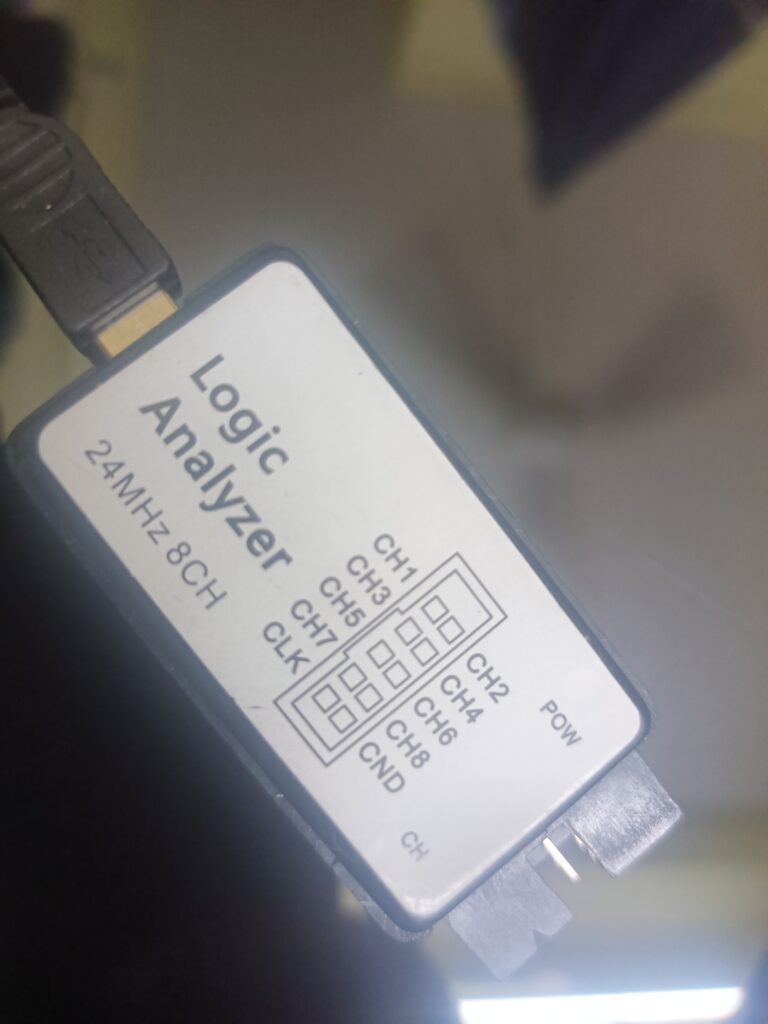
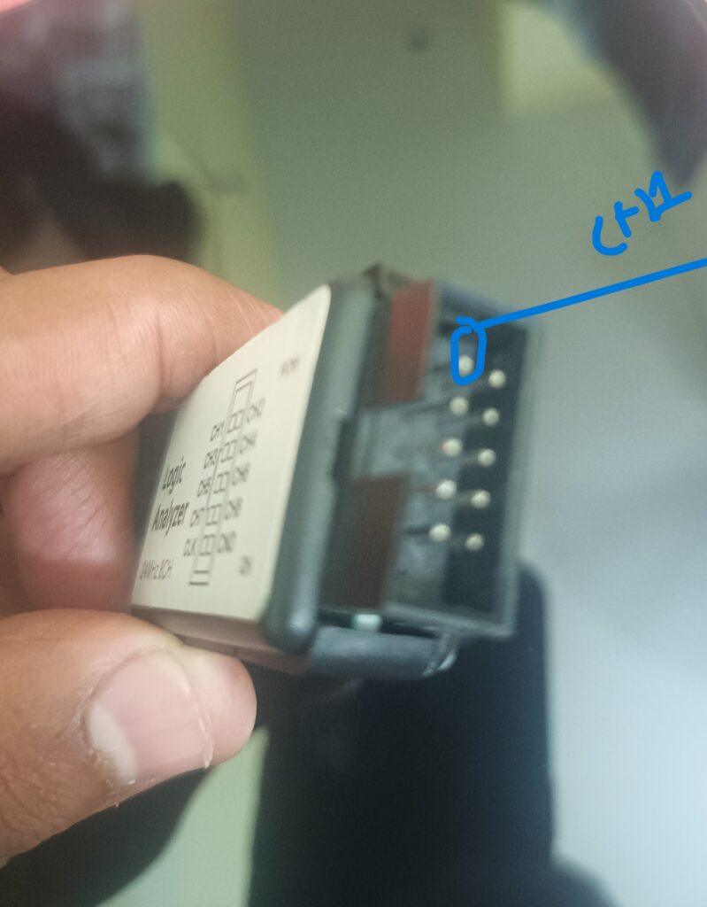
Pin of Logic Analyzer
To see what’s happening on pin 13, I connected the Saleae Logic Analyzer probe to Arduino pin 13 and ground. This allows the Logic Analyzer to measure the voltage changes as the LED turns on and off.
What I Learned from the Logic Analyzer
When I opened the Saleae software and started capturing data, I saw a clean square wave pattern on channel 0 corresponding to pin 13. The signal was HIGH for about 1 second and LOW for about 0.5 seconds, exactly as my code intended.
This visual confirmation helped me understand:
How digital signals appear as voltage changes (HIGH = ~5V, LOW = 0V).
Timing between signal changes, like the 1-second ON and 0.5-second OFF.
The importance of accurate timing in embedded programming.
Why Use a Logic Analyzer?
Debugging: It helps find errors in signal timing or logic.
Learning: Visualizing signals makes digital electronics easier to understand.
Complex Projects: When dealing with communication protocols like I2C or SPI, it’s invaluable.
Final Tips for Beginners
Always connect the ground of the Logic Analyzer to the Arduino ground.
Start with simple code like blinking an LED before moving to complex signals.
Use the Saleae software features like zoom and cursors to measure signal duration.
Don’t be afraid to experiment and observe how changes in code affect the signal.
Using a Saleae Logic Analyzer with an Arduino Uno is a fantastic way to bring digital signals to life and deepen your understanding of embedded electronics. Happy learning
You can also Visit other tutorials of Embedded Prep
These are used to manage CPU privileges, interrupt masking, and protection levels.
Register
Description
PRIMASK
Disables all interrupts except NMI when set. Used for critical sections.
FAULTMASK
Disables all exceptions including faults, except NMI.
BASEPRI
Sets a priority threshold – blocks interrupts of lower priority.
CONTROL
Controls stack pointer selection (MSP/PSP) and privilege level (Privileged/Unprivileged).
🔐 CONTROL Register (Bits)
Bit 0 – nPRIV: 0: Privileged 1: Unprivileged
Bit 1 – SPSEL: 0: Use MSP 1: Use PSP
Bit 2 – FPCA (If FPU is enabled): Floating-point context active
🧠 Summary Diagram
+------------------------+
| R0 - R12               | General-purpose registers
| R13 (SP)               | Stack Pointer (MSP or PSP)
| R14 (LR)               | Link Register (return address)
| R15 (PC)               | Program Counter
| xPSR                   | Program status flags
| MSP / PSP              | Stack pointers (Main / Process)
| PRIMASK                | Mask all interrupts except NMI
| FAULTMASK              | Mask all faults & interrupts except NMI
| BASEPRI                | Priority threshold for interrupts
| CONTROL                | Privilege + SP selection
+------------------------+
Use Case Example
void my_function(int a, int b) {
    int c = a + b;
}
While executing:
a, b, and c will likely be in R0, R1, R2
LR (R14) holds return address
SP (R13) holds the stack
PC (R15) tracks next instruction
xPSR gets updated based on the result
Let’s break down the Stack Pointer (SP), R13, and the banked versions of the Stack Pointer—MSP (Main Stack Pointer) and PSP (Process Stack Pointer)—in a detailed, beginner-friendly way, especially with relevance to ARM Cortex-M architectures.
🔹 1. What is R13 / SP?
R13 is one of the 16 general-purpose registers in the ARM architecture.
However, R13 is reserved as the Stack Pointer (SP).
So, when we say SP, it’s just an alias for R13.
💡 The stack is a region of memory used for function calls, storing local variables, return addresses, etc. The SP (R13) keeps track of the top of the stack.
🔹 2. Stack Pointer Behavior
In general:
The stack grows downward (from higher memory to lower memory).
Each time you push (store) data, SP decreases.
Each time you pop (load) data, SP increases.
🔹 3. Banked Stack Pointers: MSP and PSP
❓ Why two stack pointers?
ARM Cortex-M processors support two stack pointers for separating privileged and unprivileged stack operations:
Stack Pointer
Name
Purpose
MSP
Main Stack Pointer
Used by the OS, system handlers, and in privileged mode by default
PSP
Process Stack Pointer
Used by user/application-level code (can run in unprivileged mode)
🧠 Key Idea:
Only one stack pointer is active at a time.
The CONTROL register decides whether SP (R13) refers to MSP or PSP.
The value of MSP is set from the first word of the vector table.
RTOS context:
RTOS usually:
Keeps MSP for the kernel and system calls
Assigns PSP to individual threads/tasks
Example scenario:
Upon reset:
  SP = MSP (default)
  OS starts
  OS creates thread
  OS assigns PSP to thread
  Switch CONTROL register SPSEL to use PSP
  Thread runs with PSP (user mode)

Interrupt occurs:
  Switch to MSP (automatically)
  Handle interrupt in privileged mode
  Return from interrupt: restore PSP
🔹 6. How to Read/Write SP, MSP, PSP (Assembly or CMSIS)
Read current SP (R13):
MOV R0, SP ; Get current SP (could be MSP or PSP based on CONTROL)
Set MSP/PSP directly:
__set_MSP(0x20001000);  // Set Main Stack Pointer
__set_PSP(0x20002000);  // Set Process Stack Pointer
🔹 7. Summary Table
Term
Register
Function
SP
R13
General name for stack pointer (MSP or PSP depending on context)
MSP
Banked R13
Used by default, for kernel/system
PSP
Banked R13
Used for threads/user mode
CONTROL.SPSEL
Bit 1
Selects between MSP (0) and PSP (1)
🔹 8. Visualization
+---------------------+
|     Stack Memory    |
|---------------------|
|  High Address       |
|  ...                |
|  PSP (User Stack)   | --> Used by user tasks
|  ...                |
|  MSP (Main Stack)   | --> Used by system/IRQ
|  ...                |
|  Low Address        |
+---------------------+
🔹 9. Use Cases
RTOS-based systems: Each task/thread uses a PSP, while the kernel uses the MSP.
Security: Keeps user and kernel stacks separate.
Interrupt handling: Always uses MSP for consistency and security.
🔚 Conclusion
R13 is the generic register for the stack pointer.
In Cortex-M, it’s banked into MSP and PSP.
The CONTROL register selects which one is active.
Separation of MSP and PSP improves security and supports multitasking (RTOS).
You want to:
Use MSP by default after reset (standard behavior).
Set up a new stack region for a user task.
Switch to PSP before running that task.
Ensure CONTROL register uses PSP.
Prerequisites
Assume:
The user task stack is at 0x20002000 (adjust as per your RAM size).
Using CMSIS or direct ARM assembly.
Method 1: C (CMSIS-style)
#include "stm32f4xx.h"  // or the CMSIS header for your chip

void switch_to_psp(void) {
    uint32_t psp_stack = 0x20002000;  // Example PSP location (top of task stack)

    __set_PSP(psp_stack);             // Set the PSP
    __set_CONTROL(__get_CONTROL() | (1 << 1));  // Set CONTROL.SPSEL = 1 -> Use PSP
    __ISB();                          // Instruction Synchronization Barrier
}

int main(void) {
    switch_to_psp();  // Switch to Process Stack Pointer

    while (1) {
        // Code running with PSP
    }
}
Method 2: Pure ARM Assembly (Thumb mode)
    LDR R0, =0x20002000     ; Load new PSP address
    MSR PSP, R0             ; Move to PSP register
    MRS R0, CONTROL         ; Read CONTROL register
    ORR R0, R0, #2          ; Set bit 1 to use PSP
    MSR CONTROL, R0         ; Write back to CONTROL
    ISB                     ; Instruction Synchronization Barrier
You can embed this inline in a C function using __asm__.
Be careful not to overwrite the MSP unless you’re booting custom firmware.
Make sure 0x20002000 is a valid region in your RAM (check your linker script).
This switch is especially useful in RTOS, privilege separation, and secure context management.
Here’s a beginner-friendly tutorial on the Link Register (R14) in ARM Cortex-M4:
🌟 What is the Link Register (R14) in Cortex-M4?
The Link Register (LR) is R14, one of the special-purpose registers in the ARM Cortex-M4 processor.
It is used to store the return address when a function or an interrupt is called — so the CPU knows where to go back after executing that function.
🧠 Simple Analogy:
Think of it like this:
You go from Room A to Room B but want to return back to Room A later. So, before leaving, you write down “Room A” on a sticky note (that’s the Link Register storing the return address).
📦 Role of LR (R14) in Function Calls:
🔁 Function Call (e.g., BL func)
The BL (Branch with Link) instruction:
Jumps to the function.
Stores the return address (next instruction after BL) into R14 (LR).
🔚 Function Return
The BX LR instruction is used at the end of the function:
It reads the address in LR and jumps back to it.
main:
    BL my_function      ; Call function, save return addr in LR (R14)
    ; Continue here after my_function returns

my_function:
    ; Do something
    BX LR               ; Return to main (address stored in LR)
💥 What If LR is Lost?
If you accidentally overwrite LR before using BX LR, the processor won’t know where to return — this causes a crash or unpredictable behavior.
To prevent this, compilers or you (in assembly) save LR on the stack at the start of a function and restore it before returning.
🧰 How LR Works with Stack:
Typical function prologue and epilogue:
; Prologue (start of function)
PUSH {LR}     ; Save LR on stack

; ... function body ...

; Epilogue (end of function)
POP {LR}      ; Restore LR
BX LR         ; Return
🚨 LR in Interrupts and Exceptions:
In interrupts, the processor automatically saves LR (and other registers) on the stack.
But it sets LR to a special EXC_RETURN value — not a typical return address.
This tells the processor how to return from the exception (e.g., using BX LR with this value).
🛠️ Summary:
Feature
Details
Register Name
R14 (Link Register / LR)
Purpose
Holds return address of functions or exceptions
Used by
BL, BX LR, and exception return
Should be saved?
Yes, in nested calls or interrupts
Important in
Function calls, RTOS task switching, ISRs
✅ Tips for Beginners:
Think of LR as a “bookmark” for the CPU.
Always preserve LR if you’re writing low-level assembly functions.
Learn how the stack and LR work together.
Try writing simple ARM assembly examples to observe LR behavior.
🧠 Understanding PC (R15) in Cortex-M4: A Beginner-Friendly Guide
In ARM Cortex-M4 processors, R15 is a special-purpose register known as the Program Counter (PC). It’s one of the most important registers in any processor because it tells the CPU where to fetch the next instruction from.
What is R15 / Program Counter (PC)?
The Program Counter (PC) is register R15 in the Cortex-M4 register set.
It holds the address of the next instruction to execute.
As each instruction is executed, the PC is automatically updated to point to the next instruction.
🔍 Where is PC (R15) used?
Every instruction cycle involves the PC:
Fetch: CPU fetches the instruction at the address in PC.
Execute: The instruction is decoded and executed.
Update: PC is incremented to point to the next instruction.
For example:
MOV R0, #1   ; PC = 0x08000000
ADD R0, R0, #1 ; PC = 0x08000004
The PC increases by 4 bytes after each 32-bit instruction in Thumb-2.
📍 How is PC (R15) different from other registers?
Register
Purpose
R0–R12
General-purpose
R13
Stack Pointer (SP)
R14
Link Register (LR)
R15
Program Counter (PC)
Unlike general-purpose registers (R0–R12), you should not manipulate the PC arbitrarily unless you are doing branching, calling functions, or returning.
🔁 Branching and PC
Whenever we jump to a different part of the code, the PC is changed manually:
Example:
B   label   ; Branch to 'label', PC is updated
BL  func    ; Branch with Link (calls a function), PC is updated
BX  LR      ; Return from function, PC = LR
Fault Handling in Arm Cortex Mx Processor : Master Fault Handling in ARM Cortex-Mx processors is a crucial mechanism that helps ensure system reliability and stability by detecting, reporting, and managing faults such as memory access errors, illegal instructions, or bus errors. When a fault occurs, specialized hardware fault status registers capture detailed information about the cause and location of the fault. The processor then transfers control to fault handlers—dedicated routines designed to analyze the fault, report diagnostic information, and take remedial actions like system recovery or reset.
This fault management system includes several layers of faults, such as Hard Faults, Usage Faults, Bus Faults, and Memory Management Faults, each with specific status registers and address registers that provide rich diagnostic data. Effective fault handling in Cortex-Mx processors enables embedded developers to build robust and fault-tolerant applications critical for modern real-time and safety-critical systems.
What is a Fault in a Processor?
In embedded systems or microcontrollers (like ARM Cortex-M), a fault is a type of exception generated by the processor itself when something goes wrong during code execution. This is also called a system exception.
Think of a fault like an emergency signal that tells the processor:
“Something’s not right — we need to pause and handle this issue properly!”
Why Do Faults Happen?
Faults usually happen when:
A programmer violates the processor’s rules, like trying to divide by zero.
The processor faces a problem while dealing with external interfaces, like memory.
What happens when a fault occurs?
When a fault happens:
The processor updates internal registers with important info:
What kind of fault happened?
At which address did it occur?
If the fault exception is enabled, the processor will jump to the exception handler — a special block of code written by the programmer.
The exception handler can:
Report the error (e.g., log it)
Try to fix it (if possible)
Or stop the faulty task
Example:
If your code does this:
int a = 5 / 0;
→ It causes a divide-by-zero fault, and the Usage Fault Exception Handler (if enabled) is triggered. Inside the handler, you can decide what action to take (like terminating the task).
Types of Fault Exceptions
There are four major fault exceptions:
Exception Type
Enabled by Default?
Priority
Can Be Disabled?
Hard Fault
✅ Yes
Fixed (-1)
❌ No (only maskable using FAULTMASK)
Usage Fault
❌ No
Configurable
✅ Yes
MemManage Fault
❌ No
Configurable
✅ Yes
Bus Fault
❌ No
Configurable
✅ Yes
Causes of Faults
Here are common reasons faults can occur:
❌ Divide by zero (if divide-by-zero trap is enabled)
❌ Undefined instruction
❌ Executing code from forbidden memory region (marked as Execute Never, or XN)
❌ Violating Memory Protection Unit (MPU) rules
❌ Unaligned memory access (if unaligned access trap is enabled)
❌ Returning to thread mode with interrupts still active
❌ Bus errors (e.g., no response from SDRAM)
❌ Calling an SVC instruction from within SVC handler
⚙️ Improper debug configurations
Hard Fault Exception
What is it? A HardFault is a serious error that happens when:
A configurable fault (like usage, bus, or memory faults) cannot be handled.
Something goes wrong while processing another exception.
Why it occurs?
A lower-priority fault couldn’t be handled (escalation).
Bus error during vector table fetch.
Breakpoint instruction is executed when debugging is off.
SVC instruction executed inside SVC handler.
Priority: 3rd highest after Reset and NMI (non-maskable interrupt).
Debugging: Use the Hard Fault Status Register (HFSR) to find out what triggered the fault.
MemManage Fault Exception
Purpose: Handles memory access violations.
How to Enable: Set appropriate bits in System Handler Control and State Register (SHCSR).
Causes:
Unprivileged code (like an RTOS task) accessing privileged memory.
Writing to read-only memory regions.
Executing code from peripheral memory region (often marked XN).
Bus Fault Exception
Purpose: Raised when there is a bus error, usually while accessing memory.
How to Enable: Set the appropriate bit in SHCSR.
Causes:
Error during instruction fetch or data read/write.
Faulty or invalid memory device (e.g., SDRAM not responding).
Accessing protected memory regions.
Unprivileged access to restricted peripheral regions.
📝 Note: If a bus fault happens during vector fetch, it’s automatically escalated to a hard fault, even if bus fault is enabled.
Usage Fault Exception
Purpose: Triggered by incorrect CPU instructions or settings.
How to Enable: Configure the SHCSR register.
Causes:
Running undefined instruction.
Using floating point instructions with FPU disabled.
Trying to switch to ARM instruction set (Cortex-M only supports Thumb).
Returning to thread mode with interrupt still active.
Using unaligned memory access (if traps are enabled).
Divide by zero (if trap is enabled).
Function pointer not aligned to Thumb instruction format.
Summary
Fault Type
Typical Cause
Handler Name
Hard Fault
Unhandled faults, vector fetch errors
HardFault_Handler
MemManage Fault
MPU violations, memory access errors
MemManage_Handler
Bus Fault
Memory bus errors, invalid memory access
BusFault_Handler
Usage Fault
Illegal instructions, divide by zero, etc.
UsageFault_Handler
Final Thoughts
Faults are important safety mechanisms in embedded processors. They help you detect programming mistakes, interface issues, or system misbehavior early.
By writing proper exception handlers, you can detect, report, and recover from faults — which is essential for building robust and reliable embedded systems.
Detecting Cause of a Fault – Beginner Friendly Guide
Fault Status and Address Information
When a fault (unexpected error) happens in your program, it’s important to know why and where it happened.
To do this, inside the fault handler (a special function that runs when a fault occurs), you can check some special registers that give you more details.
These registers tell:
What caused the fault
At which instruction address the fault happened
This is very helpful for debugging your program.
Important Registers for Fault Information
📘 Hard Fault Status Register (HFSR)
Tells about a Hard Fault (a serious system error).
Configurable Fault Status Register (CFSR)
This register tells you the specific cause of a:
MemManage Fault (memory access error)
Bus Fault (bus error during instruction/data access)
Usage Fault (illegal operation like divide-by-zero)
Fault Address Information Registers
These registers store the memory addresses where the fault occurred:
MemManage Fault Address Register → Holds the address that caused a memory management fault
Bus Fault Address Register (BFAR) → Holds the address that caused a bus fault
Fault Handling and Analysis
To understand and fix faults, follow these steps:
✅ Implement a Hard Fault Handler → This is a special function to catch and handle hard faults.
✅ Analyze and Print the cause of the hard fault → Helps understand what went wrong.
✅ Print Register Contents → Print values from HFSR, CFSR, etc.
✅ Print the Last Stacked Stack Frame → Shows the program state at the time of the fault (helpful for debugging).
Error Reporting When Fault Happens
You can make your system more robust by handling faults smartly:
✅ Implement a Handler → Do something meaningful when a fault happens (like logging or safe shutdown).
✅ Implement a User Callback → Let the user define a custom error-reporting function.
🔁 Reset the Microcontroller/Processor → Restart the system if recovery isn’t possible.
🧵 In OS Environment → The task that caused the fault can be terminated and restarted.
✅ Report Register Values → Send out values from fault status and fault address registers.
🧾 Report Extra Info via Debug Tools → Print stack frame, etc., using tools like printf.
Exception For System Level Services in Arm Cortex Processor : When you’re working with ARM Cortex processors, especially in embedded systems, you’ll hear a lot about exceptions. But what are they, and how do they help your system run more smoothly — especially at the system level?
Let’s break it down simply.
Exception For System Level Services in Arm Cortex Processor
What is an Exception?
An exception is a special kind of signal that tells the processor to stop what it’s doing and do something more important first. Think of it like this:
“Hey CPU, pause your current work. There’s something urgent to handle!”
This could be an interrupt from hardware, a system fault, or even a software request like a system call.
Why Are Exceptions Important in ARM Cortex?
ARM Cortex-M processors are designed for embedded and real-time systems. Exceptions allow the processor to respond quickly to:
🔌 Hardware interrupts (like GPIO or Timer events)
🧱 Faults (like trying to access invalid memory)
🧬 System-level services (like context switching in an RTOS)
They help keep the system responsive, safe, and organized.
Types of Exceptions in Cortex-M
There are two main categories:
1. System Exceptions (Predefined by ARM)
These are built into the Cortex-M core itself. Examples:
Reset – Triggered when the system starts or restarts.
NMI (Non-Maskable Interrupt) – High-priority interrupt that can’t be disabled.
HardFault – Happens when something goes very wrong (e.g., divide by zero).
SVCall (Supervisor Call) – Used by the OS to switch between user/system mode.
PendSV – Used for context switching in RTOS (e.g., FreeRTOS).
SysTick – A system timer interrupt, often used for OS ticks.
2. External Interrupts (IRQs)
These come from outside peripherals — like buttons, UART, I2C, etc.
System-Level Services Using Exceptions
Here’s how exceptions help in system-level operations like OS scheduling:
SVCall (Supervisor Call)
When a user app needs the OS to perform a system-level task (like memory allocation), it can make a supervisor call. This triggers the SVCall exception.
Think of it like:
“Hey OS, please do something privileged for me.”
PendSV (Pendable Service Call)
The RTOS uses this to perform context switches. When it’s time to switch tasks, the OS sets PendSV as “pending”. When the CPU is ready, it runs the PendSV handler to switch tasks.
SysTick (System Timer)
This fires at regular intervals (e.g., every 1ms). It’s often used to keep track of time and schedule tasks in real-time operating systems.
Simple Real-World Use Case
Let’s say you’re building a smart fan with FreeRTOS running on a Cortex-M4:
SysTick triggers every 1ms and updates the system tick.
Based on tick count, the OS decides to switch to another task.
It sets the PendSV exception.
The processor runs the PendSV handler, which saves the current task context and switches to the next.
A user app asks for memory — it triggers SVCall to request memory allocation from the kernel.
All these system-level services run smoothly using exceptions!
Bonus: What Happens on Errors?
If your program does something wrong, the processor triggers:
HardFault
MemManage Fault
BusFault
UsageFault
These exceptions protect your system and help with debugging.
Summary
Exception
Purpose
Reset
System starts
NMI
High-priority external signal
HardFault
Serious error handling
SVCall
Request system-level services
PendSV
Context switching in RTOS
SysTick
System timekeeping
ARM Cortex-Mx processors, focusing on SVC and PendSV:
Exceptions for System-Level Services (Cortex-Mx)
The ARM Cortex-Mx processors support various exceptions, but two key system-level service exceptions used in operating systems are:
1. SVC (Supervisor Call) Exception
Purpose: Used to request privileged operations or access to system-level services from a less privileged task.
When Used: A user-mode application or thread generates an SVC exception using the SVC instruction.
Common Use Case:
Requesting services from the OS kernel such as:
Accessing peripherals
Managing device drivers
Allocating memory
Why Needed: Ensures that only authorized and controlled code (OS) can access critical system resources.
📌 Example: User task calls SVC 0x01 → triggers an SVC exception → OS handler processes it → returns result to user task.
2. PendSV (Pendable Service Call) Exception
Purpose: Designed specifically for context switching between tasks in an OS.
When Used: When a context switch is required, the OS sets the PendSV interrupt to pending.
Pendable: It is a low-priority, software-triggered exception that can be delayed until no higher-priority exceptions are active.
Common Use Case:
Task switching in RTOS (e.g., switching from Task A to Task B)
Why Needed: Ensures context switching doesn’t interfere with high-priority interrupts or exceptions.
📌 Example: Task A finishes → OS schedules Task B → PendSV is triggered → saves Task A context & restores Task B context.
Summary Table
Exception
Purpose
Trigger Source
Use Case in OS
SVC
Request system services
SVC instruction
Accessing device drivers, memory
PendSV
Perform context switching
Software
Switching between tasks
What is SVC (Supervisor Call)?
SVC is a special instruction in the Thumb Instruction Set Architecture (ISA) of ARM Cortex-M processors.
When a CPU executes SVC, it causes a special exception called the SVC exception.
This transfers control from user code (unprivileged mode) to kernel code (privileged mode).
It’s like raising your hand to ask the operating system (OS) to do something you’re not allowed to do directly.
Why Do We Use SVC?
In embedded systems or RTOS, we often run:
User tasks in unprivileged mode (to protect the system)
Since user code cannot access critical resources (like hardware registers or memory-mapped peripherals) directly, it uses SVC to request the OS to do so on its behalf.
Example Uses:
Creating/deleting tasks
Accessing hardware (GPIO, UART)
Requesting memory allocation
Starting/stopping timers
How SVC Works — Step by Step:
Let’s break it down:
1. The User Code Issues an SVC Instruction
__asm("SVC #0"); // Inline Assembly — calls SVC with number 0
The #0 is the SVC number — a value used to indicate which service you’re requesting (like a function ID).
This instruction triggers the SVC exception.
2. Processor Automatically Saves Context
When the SVC is executed:
The processor switches to handler mode (privileged mode).
It pushes some registers (R0–R3, R12, LR, PC, xPSR) onto the stack to save the current context.
This is similar to how interrupts are handled.
3. Processor Jumps to the SVC Handler
The processor now jumps to the address of the SVC handler, defined in the vector table:
void SVC_Handler(void) {
   // Kernel code handles the request here
}
4. The SVC Handler Decodes the Request
The handler checks the SVC number used in the instruction to determine what service is requested.
How to extract the SVC number:
Because the number is embedded in the instruction (not passed in R0–R3), the handler must read the instruction that caused the exception:
void SVC_Handler(void) {
    uint32_t *stack_ptr;
    uint8_t svc_number;

    // Get stack pointer (usually MSP or PSP depending on context)
    __asm("TST lr, #4\n"
          "ITE EQ\n"
          "MRSEQ %0, MSP\n"
          "MRSNE %0, PSP\n"
          : "=r" (stack_ptr));

    // Find the instruction that caused the SVC
    uint16_t *svc_instr_addr = ((uint16_t*)stack_ptr[6]) - 1;
    uint16_t svc_instr = *svc_instr_addr;

    // Extract the SVC number (last 8 bits)
    svc_number = (uint8_t)(svc_instr & 0xFF);

    switch (svc_number) {
        case 0:
            // Handle SVC #0 request
            break;
        case 1:
            // Handle SVC #1 request
            break;
        // and so on...
    }
}
5. Kernel Code Executes the Requested Service
After identifying the request (like start a task, turn on LED), the kernel performs the task in privileged mode.
6. Return to User Code
Once the handler completes, the context is restored, and execution resumes at the next instruction after SVC.
Key Points
Concept
Explanation
SVC Instruction
Causes a software exception (like a controlled interrupt)
Used By
Unprivileged user code to request services from kernel
SVC Number
A number (0–255) passed with the SVC instruction to indicate what service is needed
Handler Name
SVC_Handler() — OS or firmware must implement this
Privilege Escalation
Switches temporarily from user mode to privileged mode
Security
Ensures user tasks don’t access critical resources directly
Analogy
Think of it like this:
You are in a library (user task), and you need access to a restricted book (privileged resource).
You cannot go to the restricted section.
So, you ring a bell (SVC instruction) with a code number saying which book you want.
The librarian (SVC handler) checks your request and fetches the book on your behalf.
When Is It Used in RTOS?
Thread switching or task management
Requesting kernel services from user apps
Accessing hardware securely
System calls in embedded systems without a full-fledged OS
Summary
✅ SVC is a software interrupt used to safely access system-level services ✅ Switches from unprivileged user mode to privileged kernel mode ✅ The SVC handler reads the SVC number and executes the requested action ✅ Helps in security, task isolation, and controlled hardware access
The SVC (Supervisor Call) exception is a mechanism used in ARM Cortex-M processors to transition from unprivileged to privileged mode or to request OS services (like system calls) from the application layer. There are two methods to trigger an SVC exception:
1. Direct Execution of the SVC Instruction
This is the standard and most efficient way to trigger an SVC exception.
How it works:
The CPU executes an SVC instruction with an immediate value (which usually indicates the specific service requested).
This causes the processor to immediately enter the SVC handler, switching to Handler mode.
Example:
SVC #0x04 ; Assembly instruction to trigger SVC exception with immediate value 0x04
In C (using inline assembly or CMSIS):
__asm("SVC #0x04");
Use Cases:
Used in RTOS for system calls
Switching from Thread mode (unprivileged) to Handler mode (privileged)
Advantages:
Low latency
Immediate and deterministic triggering
Directly supported by the CPU instruction set
2. Setting the Exception Pending Bit in SHCSR (System Handler Control and State Register)
This is a less common and non-standard method used mainly for testing or simulation.
How it works:
The System Handler Control and State Register (SHCSR) contains a bit for SVC pending (SVCALLPENDED).
Manually setting this bit to 1 via software tricks the processor into thinking an SVC is pending.
When conditions allow, the SVC handler will be called.
Example:
#define SCB_SHCSR (*((volatile uint32_t*)0xE000ED24))
SCB_SHCSR |= (1 << 15);  // Set SVCALLPENDED bit manually
Bit 15 in SHCSR is SVCALLPENDED.
Important Notes:
This does not immediately trigger the SVC handler.
The exception must be enabled, and priority levels must allow it to be serviced.
Not a common practice — typically used in test environments, fault injection, or debugging.
Summary Table:
Method
Description
Efficiency
Use Case
Notes
SVC #imm
Direct instruction
✅ High
System calls, privilege switch
Standard and efficient
SHCSR bit
Set pending bit
❌ Low
Testing, debug
Uncommon and delayed execution
What is SVC?
SVC is an instruction used in ARM Cortex-M to request a privileged system service.
The syntax is: SVC #<number> Example: SVC #0x20 ; Here, 0x20 is the SVC number
Goal
When an SVC instruction is executed, it causes a SVC exception, and the processor jumps to the SVC_Handler. Your task is to:
Get the address of the SVC instruction that caused the exception.
Read the SVC opcode at that address.
Extract the SVC number from that opcode.
What Happens During SVC?
The CPU runs a line like SVC #0x05.
This triggers an SVC exception.
The CPU automatically saves some context (like registers) on the stack — this includes the Program Counter (PC) where it stopped, i.e., the instruction after the SVC.
Step-by-Step Breakdown
Step 1: Understand Stack Frame Format
When an exception like SVC occurs, ARM Cortex-M pushes the following registers onto the stack in this order:
Offset
Register
0x00
R0
0x04
R1
0x08
R2
0x0C
R3
0x10
R12
0x14
LR
0x18
PC (🟢 Points to next instruction after SVC)
0x1C
xPSR
Step 2: Get the Stack Pointer in the Handler
void SVC_Handler(void)
{
    __asm volatile
    (
        "TST lr, #4 \n"               // Test bit 2 of LR to know which stack (MSP or PSP)
        "ITE EQ \n"
        "MRSEQ r0, MSP \n"           // If 0: Main Stack Pointer
        "MRSNE r0, PSP \n"           // If 1: Process Stack Pointer
        "B SVC_Handler_C \n"         // Branch to C handler and pass r0
    );
}
Step 3: In C, Extract the SVC Number
Here is the C function that receives the stack frame pointer:
void SVC_Handler_C(uint32_t *stack_frame)
{
    // PC is at offset 6 (index 6), because each register is 4 bytes
    uint32_t return_address = stack_frame[6];

    // SVC instruction is at (return_address - 2)
    // because PC points to instruction AFTER SVC
    uint16_t *svc_instruction_address = (uint16_t *)(return_address - 2);

    uint8_t svc_number = (uint8_t)(*svc_instruction_address & 0xFF); // SVC number is in the lower byte

    // Now you can use svc_number for your logic
}
Why return_address - 2?
On Thumb instruction set (which Cortex-M uses), SVC is a 16-bit instruction.
The saved PC points to the next instruction, so subtract 2 to get the SVC instruction itself.
Read 16-bit value, extract lower byte for SVC number
Full Example: Execute SVC, extract number, increment by 4 and return
#include <stdio.h>
#include <stdint.h>

uint32_t svc_result = 0;

void SVC_Handler_Main(uint32_t *stack_frame);

__attribute__((naked)) void SVC_Handler(void) {
    __asm volatile (
        "TST lr, #4 \n"             // Test bit 2 of LR to find stack pointer (MSP or PSP)
        "ITE EQ \n"
        "MRSEQ r0, MSP \n"          // If 0, use MSP
        "MRSNE r0, PSP \n"          // Else, use PSP
        "B SVC_Handler_Main \n"     // Branch to handler in C
    );
}

// This function is called with the pointer to the stack frame
void SVC_Handler_Main(uint32_t *stack_frame) {
    // Stack frame: R0, R1, R2, R3, R12, LR, PC, xPSR
    uint16_t *pc_ptr = (uint16_t *)stack_frame[6]; // PC points to next instruction after SVC
    uint8_t svc_number = ((uint8_t *)pc_ptr)[-1];  // SVC immediate is 1 byte before PC

    printf("SVC number: %d\n", svc_number);

    svc_result = svc_number + 4;
}

uint32_t call_svc(uint8_t svc_num) {
    __asm volatile (
        "mov r0, %[num]     \n"   // Move svc_num to r0 (optional for general use)
        "svc %[immediate]   \n"   // Trigger SVC
        :
        : [num] "r" (svc_num), [immediate] "I" (0x05) // SVC #5 hardcoded for demo
        : "r0"
    );
    return svc_result;
}

int main(void) {
    printf("Calling SVC now...\n");
    uint32_t result = call_svc(5);
    printf("Returned value from SVC handler: %u\n", result);
    return 0;
}
Explanation:
SVC_Handler: Naked function with inline assembly that determines which stack pointer was used (MSP or PSP), then passes stack pointer to SVC_Handler_Main.
SVC_Handler_Main: Extracts SVC number from instruction that caused the exception (using PC - 1), prints it, increments by 4, and stores in svc_result.
call_svc(5): Executes the svc #0x5 instruction and later returns the modified result from the handler.
Output:
Calling SVC now...
SVC number: 5
Returned value from SVC handler: 9
Entry and Exit of Exception for ARM Cortex-M4 : The ARM Cortex-M4 processor is a popular microcontroller core used in embedded systems. One of its powerful features is how it handles exceptions—events that disrupt the normal flow of a program, such as interrupts, faults, or system calls.
Understanding how the Cortex-M4 enters and exits exceptions is crucial for writing reliable embedded software. This guide will walk you through the basics in a simple way.
Entry and Exit of Exception for ARM Cortex-M4
What Is an Exception?
An exception is a special event that temporarily interrupts the normal execution of a program to handle something urgent or important. Examples include:
Interrupts (external signals, like a button press or sensor input)
Faults (like memory access errors)
System calls (requests for OS services)
When an exception occurs, the processor needs to:
Save the current program state
Jump to the exception handler code
Run the handler
Restore the saved state and resume normal execution
Cortex-M4 Exception Entry: What Happens When an Exception Occurs?
When an exception is triggered, the Cortex-M4 does the following steps automatically in hardware:
1. Complete the Current Instruction
The processor finishes executing the current instruction before responding to the exception.
2. Save Context on the Stack (Automatic Stacking)
To safely pause your program, the processor saves some important registers on the current stack (either Main Stack Pointer (MSP) or Process Stack Pointer (PSP)):
R0 to R3 (general-purpose registers)
R12
LR (Link Register)
PC (Program Counter)
xPSR (Program Status Register)
This saved context is called the Exception Stack Frame. Saving these registers means the processor remembers exactly where it left off.
3. Load the Exception Handler Address
The processor reads the address of the exception handler (from the Vector Table) and jumps to it. The handler is just a special function in your code that deals with the exception.
4. Change Processor State
The processor sets some internal flags to indicate it’s now running in Handler Mode (instead of Thread Mode).
Cortex-M4 Exception Exit: Returning to Normal Execution
When the exception handler finishes, it needs to return control back to the original program. This happens by executing the BX LR or returning from the handler function.
Here’s what happens during exit:
1. Restore Context (Automatic Unstacking)
The processor automatically restores the saved registers (R0-R3, R12, LR, PC, xPSR) from the stack. This means the program state is back exactly as it was before the exception.
2. Return to Thread Mode
The processor switches back from Handler Mode to Thread Mode, resuming normal program execution.
Key Points to Remember
Step
What Happens
Cortex-M4 Feature
Exception Entry
Save CPU registers on stack
Automatic stacking mechanism
Jump to exception handler address
Vector Table lookup
Switch to Handler Mode
Hardware-controlled
Exception Handler Run
Execute the exception service routine
Software-defined
Exception Exit
Restore CPU registers from stack
Automatic unstacking
Return to the exact instruction in program
Resume Thread Mode
Visual Overview
Normal Program Execution
        ↓
   Exception Occurs
        ↓
[Automatic save registers on stack]
[Jump to Handler]
   Exception Handler runs
        ↓
[Automatic restore registers from stack]
[Return to Normal Execution]
Why Is This Important?
Automatic stacking/unstacking saves you from writing complex assembly code.
You can rely on hardware to preserve the state of your program.
Understanding this flow helps you write safe and efficient interrupt handlers.
Helps in debugging exceptions and faults by knowing what the processor does internally.
Complete basic example of handling an external interrupt on an STM32F4
GPIO configuration for a button input
EXTI (external interrupt) setup on that GPIO pin
NVIC interrupt enabling
The actual interrupt handler code
Complete Example: GPIO Button Interrupt on STM32F4 (Cortex-M4)
Assumptions:
You have STM32Cube HAL library or similar to handle low-level register operations (for simplicity).
Button connected to GPIOA Pin 0.
LED connected to GPIOG Pin 13 (just for indication).
1. Include headers and define pins:
#include "stm32f4xx.h"      // Device header, adjust for your MCU
#include "stm32f4xx_hal.h"  // HAL header for STM32
2. GPIO and EXTI Initialization:
void GPIO_EXTI_Init(void)
{
    // Enable GPIOA and GPIOG clocks
    __HAL_RCC_GPIOA_CLK_ENABLE();
    __HAL_RCC_GPIOG_CLK_ENABLE();

    // Configure PA0 as input with pull-up (Button pin)
    GPIO_InitTypeDef GPIO_InitStruct = {0};
    GPIO_InitStruct.Pin = GPIO_PIN_0;
    GPIO_InitStruct.Mode = GPIO_MODE_IT_RISING;  // Interrupt on rising edge (button press)
    GPIO_InitStruct.Pull = GPIO_PULLUP;
    HAL_GPIO_Init(GPIOA, &GPIO_InitStruct);

    // Configure PG13 as output (LED pin)
    GPIO_InitStruct.Pin = GPIO_PIN_13;
    GPIO_InitStruct.Mode = GPIO_MODE_OUTPUT_PP; // Push-pull output
    GPIO_InitStruct.Pull = GPIO_NOPULL;
    GPIO_InitStruct.Speed = GPIO_SPEED_FREQ_LOW;
    HAL_GPIO_Init(GPIOG, &GPIO_InitStruct);

    // Enable and set EXTI line 0 Interrupt to the lowest priority
    HAL_NVIC_SetPriority(EXTI0_IRQn, 2, 0);
    HAL_NVIC_EnableIRQ(EXTI0_IRQn);
}
3. Interrupt Handler Function
void EXTI0_IRQHandler(void)
{
    // Check if EXTI line 0 caused the interrupt
    if(__HAL_GPIO_EXTI_GET_IT(GPIO_PIN_0) != RESET)
    {
        __HAL_GPIO_EXTI_CLEAR_IT(GPIO_PIN_0);  // Clear the interrupt flag

        // Toggle LED on PG13
        HAL_GPIO_TogglePin(GPIOG, GPIO_PIN_13);
    }
}
4. Main Function Example
int main(void)
{
    HAL_Init();                 // Initialize HAL Library
    SystemClock_Config();       // Configure system clock (user-defined, MCU specific)
    GPIO_EXTI_Init();           // Initialize GPIO and EXTI

    while(1)
    {
        // Main loop can do other stuff
    }
}
Explanation:
GPIO_EXTI_Init() configures the button pin as an input interrupt source and sets up the LED pin as output.
HAL_NVIC_EnableIRQ(EXTI0_IRQn) enables the EXTI0 interrupt in the Nested Vector Interrupt Controller.
When the button connected to PA0 is pressed (rising edge), the Cortex-M4 automatically:
Pushes registers on the stack (exception entry)
Jumps to EXTI0_IRQHandler
The handler clears the interrupt flag and toggles the LED.
On return, the processor restores the registers and resumes normal execution.
What is EXC_RETURN?
In ARM Cortex-M (e.g., Cortex-M4), when an exception (like an interrupt or fault) occurs, the processor automatically saves some registers and branches to an exception handler.
When the handler finishes, the processor restores context using a special magic value called EXC_RETURN, which is loaded into the Program Counter (PC). This value tells the processor how to restore context and return to the previous state.
Breakdown of EXC_RETURN Values (from the image)
Value
Meaning
0xFFFFFFF1
Return to Handler Mode, use Main Stack Pointer (MSP), no FPU context
0xFFFFFFF9
Return to Thread Mode, use MSP, no FPU context
0xFFFFFFFD
Return to Thread Mode, use Process Stack Pointer (PSP), no FPU context
0xFFFFFFE1
Return to Handler Mode, use MSP, with FPU context
0xFFFFFFE9
Return to Thread Mode, use MSP, with FPU context
0xFFFFFFED
Return to Thread Mode, use PSP, with FPU context
Bitwise Meaning (EXC_RETURN is 32-bit value)
Only the lower 5 bits are meaningful:
Bit
Meaning
0
Always 1
2
1 = Return to Thread mode, 0 = Handler mode
3
1 = Use PSP, 0 = Use MSP
4
1 = FPU context present, 0 = No FPU context
Example
If EXC_RETURN = 0xFFFFFFFD (binary ends in 11111111111111111111111111111101):
Bit 2 = 1 → Return to Thread mode
Bit 3 = 1 → Use PSP
Bit 4 = 0 → No FPU context
Why is this important?
When writing custom context switchers, RTOS code, or exception handlers (like SVC or PendSV), the correct EXC_RETURNvalue ensures the system:
Restores the right registers
Returns to the correct mode
Uses the correct stack
Handles FPU state (if available and used)
What is EXC_RETURN?
EXC_RETURN is a special constant value loaded into Link Register (LR)during exception entry.
This value tells the processor how to restore the previous context when returning from the exception (which stack to use, which mode to return to, whether FPU state is involved).
When is EXC_RETURN Generated?
It is not stored in the LR by your C code—it is done automatically by the processor.
🔹 During exception entry, the processor puts an EXC_RETURN value into LR instead of the return address (like normal function calls do).
So, when the handler finishes, and you do BX LR, the processor interprets LR as EXC_RETURN and uses that info to exit the exception properly.
Full Exception Entry Sequence (Step-by-Step)
1. Pending Bit is Set
An interrupt/exception is pending (from NVIC or system fault).
2. Stacking and Vector Fetch
Processor automatically saves the current execution context (R0–R3, R12, LR, PC, xPSR) onto the current stack (MSP or PSP).
Then, it fetches the exception vector from the vector table.
3. Entry into the Handler and Active Bit Set
Processor enters the exception handler.
The corresponding Active bit is set (in the Interrupt Control State Register, ICSR).
4. EXC_RETURN Value is Placed in LR
Instead of storing the normal return address, the processor stores a special EXC_RETURN value in LR to indicate how to resume execution. For example: LR = 0xFFFFFFFD // Return to Thread mode, use PSP, no FPU
🔸 5. Pending Bit is Cleared Automatically
As soon as the processor starts executing the exception handler, the Pending bit is cleared (except for some faults like NMI).
🔸 6. Processor Mode is Now Handler Mode
The CPU switches from Thread mode to Handler mode.
Execution privileges may change (Handler is usually in privileged mode).
🔸 7. MSP is Used
The Main Stack Pointer (MSP) is automatically selected and used for stack operations during the handler, unless you manually configured to use PSP.
🔚 What Happens at Exception Return?
The handler ends by executing: BX LR
The processor checks the EXC_RETURN value in LR and:
Determines which mode to return to (Thread or Handler)
Decides which stack to use (MSP or PSP)
Checks whether to restore FPU state (if applicable)
The processor pops the stack to restore R0-R3, R12, LR, PC, and xPSR.
ARM Cortex-M4 Interrupt Handling : In embedded systems, handling asynchronous events like incoming data from external devices is crucial for responsive and efficient software design. One powerful mechanism used for this purpose is interrupts. Instead of continuously polling a peripheral, the microcontroller (MCU) can be configured to automatically respond to specific events, such as data arrival in a UART (USART) buffer.
This article walks you through the step-by-step interrupt handling process using a USART peripheral as an example. You’ll learn how the data flow, NVIC (Nested Vectored Interrupt Controller), and CPU work together to handle interrupts — from the moment a data packet arrives, to executing the interrupt service routine (ISR) that processes the data.
Whether you’re working with ARM Cortex-M microcontrollers or just beginning your journey into embedded development, this guide will help you build a clear mental model of how peripheral interrupts operate under the hood.
ARM Cortex-M4 Interrupt Handling
Core Peripheral Register Regions (ARM Cortex-M)
Address Range
Core Peripheral
Description
0xE000E008 – 0xE000E00F
System Control Block (SCB)
Contains control and status registers like ACTLR, used for system configuration.
0xE000E010 – 0xE000E01F
System Timer (SysTick)
A 24-bit timer that provides a simple way to generate delays or time slices.
0xE000E100 – 0xE000E4EF
Nested Vectored Interrupt Controller
Manages external and internal interrupt handling with programmable priorities.
0xE000ED00 – 0xE000ED3F
System Control Block (Extended)
Additional system control and status registers including CPUID, ICSR, etc.
0xE000ED90 – 0xE000ED93
MPU Type Register
Used to detect if MPU is implemented. If value reads 0, then MPU is not present.
0xE000ED90 – 0xE000EDB8
Memory Protection Unit (MPU)
Defines memory regions and their attributes to prevent invalid memory access.
0xE000EF00 – 0xE000EF03
NVIC (Software Trigger Interrupt Reg)
Used to trigger interrupts through software.
0xE000EF30 – 0xE000EF44
Floating Point Unit (FPU)
Registers and controls for the floating-point coprocessor (if supported).
NVIC (Nested Vectored Interrupt Controller) registers in ARM Cortex-M microcontrollers.
Explanation of Each Row
Field
Meaning
Address
Memory range for the register(s)
Name
Name of the register
Type
RW = Read/Write, WO = Write-Only
Required privilege
Access level needed (Privileged or Configurable)
Reset value
Default value after reset (usually all 0s = disabled)
Look up the IRQ number of the peripheral in the MCU’s vector table.
Example: For USART3, the IRQ number might be 39 (vendor-specific).
📌 This IRQ number maps to an entry in the NVIC interrupt table, and it’s essential to configure it correctly.
2. Enable the IRQ in the Processor
Use the NVIC_ISERx (Interrupt Set-Enable Register) to enable the IRQ number.
Optionally, use the NVIC_IPRx (Interrupt Priority Register) to set its priority.
NVIC_ISER1 |= (1 << (39 % 32));       // Enable IRQ39
NVIC_IPR9 = (3 << 6);                 // Optional: Set priority for IRQ39 (lower value = higher priority)
📘 The processor won’t recognize interrupts unless they’re enabled in NVIC.
3. Configure the Peripheral
Set up the peripheral (e.g., USART3) to generate an interrupt.
This is done through its own control/status registers (e.g., USART_CR1 for enabling RXNEIE — RX Not Empty Interrupt Enable).
USART3->CR1 |= USART_CR1_RXNEIE; // Enable RX interrupt for USART3
4. Pending Register Behavior
When USART3 receives data, it automatically issues an interrupt on IRQ 39.
This interrupt gets logged (pended) in the NVIC_ISPRx (Interrupt Set-Pending Register).
5. NVIC Checks Priority Before Serving
NVIC checks:
Is the IRQ enabled?
Is the priority of this interrupt higher than the one currently being served?
If yes, it triggers the Interrupt Service Routine (ISR).
If no, the interrupt stays pending until it becomes the highest-priority pending interrupt.
6. Interrupt Behavior When IRQ is Disabled
Even if you haven’t enabled the IRQ in NVIC, the peripheral can still issue the interrupt.
It gets stored in the pending state.
When you later enable the IRQ:
If its priority is high enough, the ISR will execute immediately.
Summary Flow:
Peripheral event (e.g., USART3 receives data) -->
Peripheral asserts IRQ (e.g., IRQ39) -->
NVIC pends the IRQ (ISPRx) -->
If enabled and high-priority, NVIC dispatches ISR -->
Your code executes the ISR (Interrupt Service Routine)
Interrupt Handling Flow for USART RX Data
Step 1: Data Arrival
What happens: A data packet comes in from the external world and is received by the USART RX buffer.
Where: In the USART peripheral (e.g., USART3).
Why: Because a device (e.g., another MCU, terminal, etc.) is sending data over the serial line.
Step 2: Interrupt Request Issued
What happens: The USART peripheral detects new data in its RX buffer and triggers an interrupt.
How: It asserts its IRQ line (in this case, IRQ number 39) to notify the processor.
📌 This step depends on the fact that RX interrupt is enabled in the peripheral control register (USART_CR1).
Step 3: NVIC Registers the Interrupt
What happens:
The IRQ 39 becomes pending in the NVIC’s pending register (ISPRx).
If the IRQ is enabled and has sufficient priority, NVIC prepares to handle it.
Visual: This is shown as the yellow box inside NVIC with a 39 marked line going into the pending register.
Step 4: CPU Handles Interrupt
What happens:
CPU fetches the ISR address from the vector table based on IRQ number 39.
CPU jumps to the ISR (Interrupt Service Routine).
Note: The Program Counter (PC) is updated with the ISR address.
Step 5: ISR Executes
What happens: The ISR (Interrupt Service Routine) runs.
What it does: It typically copies the received data from the USART RX buffer into SRAM (main memory) or processes it accordingly.
Summary Flowchart:
External Data → USART RX Buffer
       ↓
USART Issues IRQ (e.g., 39)
       ↓
NVIC Marks IRQ as Pending (if enabled)
       ↓
CPU Fetches ISR from Vector Table
       ↓
ISR Executes (e.g., copy data to SRAM)
Developer Notes:
This entire flow is hardware-assisted and efficient, allowing the CPU to react quickly to events without polling.
You must:
Enable RX interrupt in USART.
Enable IRQ in NVIC.
Write the correct ISR function in your firmware.
Interrupt Priority, Preempt Priority & Sub Priority
In embedded systems, interrupts help your program quickly respond to important events (like a button press or sensor signal) even while it’s doing something else. But what happens when two or more interrupts occur at the same time?
That’s where priority comes in!
What is Interrupt Priority?
Every interrupt is assigned a priority to help the microcontroller decide which interrupt to serve first.
👉 Higher priority interrupts get serviced before lower priority ones.
For example:
If Timer1 (priority 2) and USART1 (priority 1) occur at the same time, USART1 will be handled first.
What is Preempt Priority?
Preempt Priority decides whether one interrupt can interrupt another that’s already running.
🔁 If a new interrupt with higher preempt priority comes while another is running, it will preempt (pause) the running one and start executing.
👉 Think of it like a teacher calling a more urgent student to speak even if another student is already speaking.
What is Sub Priority?
Sub Priority helps decide which interrupt runs first when two interrupts have the same preempt priority.
⚠️ Sub-priority does not cause preemption — it only helps resolve the order when two interrupts are pending with the same level.
Example Analogy:
Interrupt
Preempt Priority
Sub Priority
Meaning
USART1
1
1
Medium importance
Timer2
0
0
Highest importance
EXTI0 (button)
1
0
Medium but slightly more urgent
Example Code: STM32 Interrupt Priority
Let’s use STM32CubeIDE and configure priorities for 3 interrupts:
EXTI0 (button)
TIM2 (timer)
USART1 (serial communication)
NVIC Priority Configuration
// main.c or user init function
HAL_NVIC_SetPriorityGrouping(NVIC_PRIORITYGROUP_2); // 2 bits for preemption, 2 for sub-priority

// Set TIM2 interrupt: Highest priority
HAL_NVIC_SetPriority(TIM2_IRQn, 0, 0); // Preempt: 0, Sub: 0
HAL_NVIC_EnableIRQ(TIM2_IRQn);

// Set EXTI0 interrupt: Mid priority
HAL_NVIC_SetPriority(EXTI0_IRQn, 1, 0); // Preempt: 1, Sub: 0
HAL_NVIC_EnableIRQ(EXTI0_IRQn);

// Set USART1 interrupt: Lowest priority
HAL_NVIC_SetPriority(USART1_IRQn, 1, 1); // Preempt: 1, Sub: 1
HAL_NVIC_EnableIRQ(USART1_IRQn);
ISR (Interrupt Service Routines)
void TIM2_IRQHandler(void)
{
    HAL_TIM_IRQHandler(&htim2);
    HAL_GPIO_TogglePin(GPIOC, GPIO_PIN_13); // Toggle LED
}

void EXTI0_IRQHandler(void)
{
    HAL_GPIO_EXTI_IRQHandler(GPIO_PIN_0);
    HAL_UART_Transmit(&huart1, (uint8_t*)"EXTI0 triggered\n", 16, HAL_MAX_DELAY);
}

void USART1_IRQHandler(void)
{
    HAL_UART_IRQHandler(&huart1);
    // Maybe echo back received data
}
Summary
Term
Controls
Can Interrupt Others?
Purpose
Preempt Priority
Whether one ISR interrupts another
✅ Yes
Preemption behavior
Sub Priority
Order if same preempt level
❌ No
Resolves conflict silently
Notes
HAL_NVIC_SetPriority uses (preempt, sub) as inputs.
Lower number = Higher priority.
Priority grouping sets how bits are divided between preempt and sub.
NVIC Interrupt Priority Configuration and Manual Triggering on STM32
#if !defined(__SOFT_FP__) && defined(__ARM_FP)
  #warning "FPU is not initialized, but the project is compiling for an FPU. Please initialize the FPU before use."
#endif#define IRQNO_TIMER2  28
#define IRQNO_I2C1    31

#include <stdint.h>
#include <stdio.h>

// NVIC Register Base Addresses (Cortex-M processor specific)
uint32_t *pNVIC_IPRBase  = (uint32_t*)0xE000E400; // Priority Register
uint32_t *pNVIC_ISERBase = (uint32_t*)0xE000E100; // Interrupt Set-Enable
uint32_t *pNVIC_ISPRBase = (uint32_t*)0xE000E200; // Interrupt Set-Pending

// Function to configure priority for a given IRQ number
void configure_priority_for_irqs(uint8_t irq_no, uint8_t priority_value)
{
    uint8_t iprx = irq_no / 4;
    uint32_t *ipr = pNVIC_IPRBase + iprx;

    uint8_t pos = (irq_no % 4) * 8;

    *ipr &= ~(0xFF << pos);                // Clear existing priority
    *ipr |=  ((priority_value & 0xFF) << pos);  // Set new priority
}

int main(void)
{
    // Configure priorities
    configure_priority_for_irqs(IRQNO_TIMER2, 0x80);
    configure_priority_for_irqs(IRQNO_I2C1,  0x70);

    // Set TIM2 interrupt as pending
    *pNVIC_ISPRBase |= (1 << IRQNO_TIMER2);

    // Enable IRQs
    *pNVIC_ISERBase |= (1 << IRQNO_I2C1);
    *pNVIC_ISERBase |= (1 << IRQNO_TIMER2);

    while(1); // Wait here forever
}

// Timer 2 Interrupt Handler
void TIM2_IRQHandler(void)
{
    printf("[TIM2_IRQHandler] - Triggering I2C1 IRQ...\n");

    // Manually pend I2C1 interrupt from within TIM2 handler
    *pNVIC_ISPRBase |= (1 << IRQNO_I2C1);

    while(1); // Stay here to simulate nested interrupt scenario
}

// I2C1 Event Interrupt Handler
void I2C1_EV_IRQHandler(void)
{
    printf("[I2C1_EV_IRQHandler] - Nested interrupt handled.\n");
}
ARM Cortex-M Exception Handling: In ARM Cortex-M, exceptions are interrupts and system events that cause the processor to temporarily stop the main program and execute a special function (handler) to deal with it.
✅ Cortex-M CPUs have a built-in Nested Vectored Interrupt Controller (NVIC) that supports exceptions, prioritization, nesting, and vector table.
Types of Exceptions
Category
Examples
Triggered By
System Exceptions
Reset, NMI, HardFault, SysTick, PendSV, etc.
System events or faults
Fault Exceptions
MemManage, BusFault, UsageFault
Errors in code or hardware
External Interrupts (IRQs)
Timer, GPIO, UART, etc.
Peripheral hardware requests
What is an Exception?
An exception is a special event that interrupts the normal program execution and transfers control to a special function called an exception handler.
You can think of it like this:
“Hey CPU, stop what you’re doing. Something important just happened. Handle it now!”
Types of Exceptions in Cortex-M4
The ARM Cortex-M4 processor has two main types of exceptions:
Type
Description
Interrupts (IRQs)
Triggered by external devices like timers, buttons, UART, etc.
System Exceptions
Triggered internally by the processor (like faults, system calls, etc.)
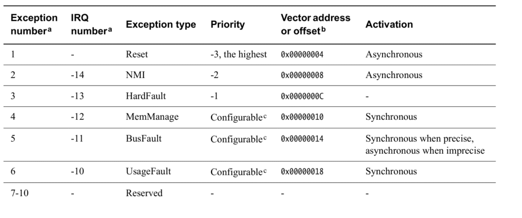
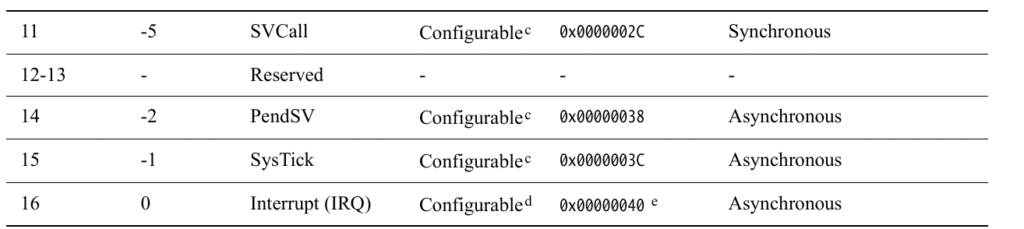
List of System Exceptions (with vector numbers)
Here are some common system exceptions:
Exception Name
Vector Number
Description
Reset
1
Happens when the processor starts or is reset.
NMI (Non-Maskable Interrupt)
2
A high-priority interrupt that cannot be disabled.
HardFault
3
Happens when something goes seriously wrong (e.g., invalid memory access).
MemManage Fault
4
Memory protection violation.
BusFault
5
Bus error during instruction/data access.
UsageFault
6
Illegal instructions (like divide by zero, etc).
SVCall
11
Supervisor Call (used in RTOS or OS).
PendSV
14
Used in context switching in RTOS.
SysTick
15
Timer interrupt, often used for OS ticks.
What Happens When an Exception Occurs?
Processor saves context (automatically):
Saves registers: R0-R3, R12, LR, PC, xPSR onto the stack.
Jumps to the exception handler:
The address is taken from the vector table.
Executes handler function.
Returns to where it was using BX LR or exception return sequence.
Vector Table
The vector table is a list of addresses stored at the beginning of memory (0x00000000). Each entry is a pointer to the handler for each exception.
Happens when no other fault handler catches the error.
Example: Dereferencing a NULL pointer.
2. MemManage Fault
Related to memory protection (MPU).
Example: Accessing restricted memory.
3. BusFault
Caused by bus errors during instruction fetch or data access.
Example: Accessing non-existent memory address.
4. UsageFault
Caused by incorrect use of instructions.
Example: Division by zero, unaligned access.
How to Write a Simple Exception Handler
Example for HardFault:
void HardFault_Handler(void) {
    while (1) {
        // Stay here forever - you can add logging or LED blink
    }
}
SysTick and PendSV (RTOS Related)
SysTick: Regular timer interrupt (e.g., every 1ms) used to keep track of time.
PendSV: Used for context switching in operating systems.
These are critical for implementing real-time operating systems.
Registers Involved
xPSR (Program Status Register): Gives status of current program state.
LR (Link Register): Helps in return from exception.
PC (Program Counter): Address of the instruction being executed.
Debugging Tips
Check the value of the LR (Link Register) to know where the exception came from.
You can decode the value of LR to understand the exception return type (called EXC_RETURN).
Exception Types in Cortex-M4 (Made Simple)
1. Reset
What is it? It happens when you first turn on the microcontroller (power-up) or when it’s manually reset (like pressing a reset button).
What does it do? The processor starts from the beginning — it looks at a specific address (in the vector table) and starts running your main code.
Think of it like: Turning off and on your computer — it restarts from scratch.
2. NMI (Non-Maskable Interrupt)
What is it? It’s a very important interrupt that cannot be ignored or turned off.
When does it happen? Triggered by special hardware problems or important peripherals.
Why is it special?
It can’t be blocked by other interrupts.
Only the Reset has a higher priority than NMI.
Think of it like: A fire alarm — it will ring no matter what else is going on.
3. HardFault
What is it? A major error that happens when something really bad occurs — like accessing invalid memory or when another exception fails.
When does it happen?
Program tries to use a bad address.
An exception cannot be handled properly.
What makes it special?
Has very high priority (second only to Reset and NMI).
Can’t be ignored if it happens.
Think of it like: A system crash or blue screen. The processor doesn’t know what to do and enters a special error state.
4. MemManage Fault
What is it? A memory access error — trying to read or write to protected or forbidden areas in memory.
Example: Trying to execute code in a non-executable area.
Think of it like: You tried opening a locked door. You’re not allowed in.
5. BusFault
What is it? Happens when something goes wrong while moving data to or from memory (like over a bus).
Example: You try to read from a memory location that doesn’t respond or doesn’t exist.
Think of it like: A delivery truck goes to an address, but no one is there to accept the package.
6. UsageFault
What is it? Happens when you use instructions incorrectly.
Examples:
Using an undefined instruction
Dividing by zero
Using misaligned memory access
Think of it like: Typing a wrong command in a computer program — something the processor doesn’t understand.
7. SVCall (Supervisor Call)
What is it? It’s triggered by a special instruction in the program (called SVC).
Why is it used? To ask the operating system for help — like calling a system function or driver.
Think of it like: A customer service call — your code is asking the OS for assistance.
8. PendSV (Pending Supervisor Call)
What is it? A special interrupt used for context switching in an operating system.
When is it used? When the OS wants to switch from one task to another.
Think of it like: Switching between open apps on your phone — only when the current one is done.
9. SysTick
What is it? A system timer interrupt that goes off at regular time intervals (like every 1 millisecond).
Why is it useful?
Used by RTOS (real-time operating systems) to keep track of time.
Helps schedule tasks.
Think of it like: A ticking clock that reminds the CPU to check tasks.
10. Interrupt (IRQ)
What is it? Regular interrupts triggered by external devices like:
Timers
Buttons
Sensors
Why are they important? Peripherals use IRQs to alert the processor when they need attention.
Think of it like: Your phone buzzing — something needs your attention.
Summary Table
Exception Type
Simple Meaning
Who Triggers It
Can It Be Turned Off?
Reset
System restart
Power or reset button
No
NMI
Emergency interrupt
Hardware
No
HardFault
Serious error
Processor
No
MemManage
Bad memory access
Processor
Yes
BusFault
Memory bus error
Processor
Yes
UsageFault
Wrong instruction
Processor
Yes
SVCall
System service request
Software
Yes
PendSV
Task switch request
Software/OS
Yes
SysTick
Timer interrupt
Timer
Yes
IRQ
Normal interrupt
Peripherals
Yes
Final Notes
Exceptions help the processor react to important or error conditions.
Some are triggered by hardware (like Reset, NMI), some by your own code (like SVCall).
Faults like HardFault, UsageFault help catch bugs and protect your system.
What Are Exception States?
When an exception (like an interrupt or a fault) occurs, the processor doesn’t just instantly handle it — instead, that exception goes through different states.
Think of it like a queue at a doctor’s clinic:
You wait your turn (Pending)
You go inside to be treated (Active)
You’re done and leave (Inactive)
And sometimes, you’re inside while someone else knocks — that’s Active and Pending!
The 4 States of an Exception
1. Inactive
What it means: Nothing is happening — the exception is not triggered or being serviced.
Example: No interrupt from a button press or sensor — the CPU is doing regular work.
2. Pending
What it means: The exception is waiting to be handled by the processor.
How it gets here:
A peripheral device (like a timer or sensor) sends an interrupt.
Software writes to a register to generate an interrupt.
Example: You press a button → that sends an interrupt → the exception becomes pending, waiting for the CPU to respond.
3. Active
What it means: The CPU is currently handling the exception — it’s running the exception handler code.
Example: The CPU stops what it was doing and jumps to the interrupt handler for your button press.
4. Active and Pending
What it means: The CPU is already handling this exception, and another one just came in from the same source — so now it’s both active and pending.
Important Note:
The CPU won’t handle the new request until the current one finishes.
This can happen if, for example, a timer interrupt happens again while the CPU is still handling the previous one.
Key Notes (Simplified)
🔁 Can one exception interrupt another?
Yes! If a higher priority exception occurs while a lower priority one is being handled, it can interrupt it. Then both are in Active state, but the higher one is being serviced.
Table Summary
State
What it means
Inactive
Nothing is happening. Not triggered or running.
Pending
Waiting in line. Triggered but not yet handled.
Active
CPU is handling it right now.
Active & Pending
CPU is still handling it, but another trigger from the same source just came.
Real-World Analogy
Imagine you’re a doctor (CPU) at a clinic:
Inactive: No patients in the waiting room.
Pending: A patient arrives and takes a seat in the waiting room.
Active: You’re currently treating a patient.
Active & Pending: While treating a patient, the same patient sends a new report (like a new symptom appears) — you’ll check that next.
What is the System Control Block (SCB)?
The System Control Block (SCB) is a special part of the ARM Cortex-M microcontroller that helps the system control and manage important operations, especially related to exceptions and faults (like errors or interrupts).
Think of SCB as the “Control Room” of the system
Just like a control room in a building handles alarms, system messages, and settings, the SCB handles things like:
Configuration settings
Control of system behavior
Reports on errors and exceptions
What exactly does SCB do?
Stores Information:
It contains information about how the system is set up.
For example, it knows what kind of CPU core you’re using and other system details.
Controls Exceptions:
Exceptions are special events like:
An interrupt from a timer
A fault caused by invalid memory access
SCB helps control how the system responds to these events.
Helps in Debugging:
It can report errors or faults that occur, which helps you debug your code.
Where is it used?
It’s part of the core of ARM Cortex-M processors.
Used when handling:
Fault exceptions like hard faults or memory faults
System resets
Vector table settings (which tell the system what to do when something happens)
Registers in SCB (just names for now):
Here are some important registers inside the SCB (you don’t have to memorize them yet):
CPUID: Tells which processor you’re using
ICSR: Controls system exceptions
AIRCR: Lets you request a system reset
SCR: Controls system sleep modes
CCR: Enables/disables certain features like fault trapping
SHCSR: Shows which exceptions are enabled or active
In Short:
The SCB is a built-in control unit in ARM Cortex-M processors that manages exceptions, faults, and system control features like resets and sleep modes. It’s like the system’s supervisor.
System Control Block (SCB) registers are part of the Cortex-M System Control Space, which provides system-level configuration and control features like interrupt priority, fault handling, system reset, and debug support.
Here’s a breakdown of each column:
Columns
Column
Meaning
Address
The memory-mapped address of the register in the SCB address space.
Name
Name of the register.
Type
Read/Write access: RW (Read/Write), RO (Read-Only), etc.
Required Privilege
Only privileged code (like kernel or supervisor mode) can access it.
Reset Value
The value stored in the register after reset.
Description
Function of the register.
Important Registers Explained
Register
Address
Purpose
ACTLR
0xE000E008
Auxiliary Control Register – Enables/Disables implementation-specific features.
CPUID
0xE000ED00
CPUID Base Register – Read-only; identifies the processor type and revision.
ICSR
0xE000ED04
Interrupt Control and State Register – Controls pending interrupts and tracks the current interrupt number.
VTOR
0xE000ED08
Vector Table Offset Register – Points to the interrupt vector table in memory.
AIRCR
0xE000ED0C
Application Interrupt and Reset Control Register – Software reset, endianness config, interrupt priority grouping.
SCR
0xE000ED10
System Control Register – Configures deep sleep, sleep-on-exit, etc.
CCR
0xE000ED14
Configuration and Control Register – Enables stack alignment, fault traps, etc.
SHPRx
0xE000ED18 to 0xE000ED20
System Handler Priority Registers – Set priorities for system exceptions like SVCall, PendSV, SysTick.
SHCSR
0xE000ED24
System Handler Control and State Register – Enables system exceptions and indicates their active/pending states.
CFSR
0xE000ED28
Configurable Fault Status Register – Reports details of usage, bus, or memory faults.
MMSR/BFSR/UFSR
(parts of CFSR)
Subfields of the CFSR to provide more specific fault information.
HFSR
0xE000ED2C
HardFault Status Register – Indicates causes of HardFault exceptions.
MMAR
0xE000ED34
MemManage Fault Address Register – Address that caused memory fault.
BFAR
0xE000ED38
BusFault Address Register – Address that caused bus fault.
AFSR
0xE000ED3C
Auxiliary Fault Status Register – Optional register for vendor-specific fault status.
Key Concepts
Privileged Access: These registers can only be modified in privileged mode, ensuring the kernel has control over critical system behavior.
Reset Values: These default values indicate the state of the register after a system reset.
Exception Handling: Many of these registers are used for handling and prioritizing faults/exceptions.
Enable PendSV and fault exceptions (Memory Management, BusFault, UsageFault) on an ARM Cortex-M processor, you’ll work with specific SCB system control registers. These are:
1. Enabling PendSV Exception
PendSV (Pendable Service Call) is enabled by default, but you may need to:
Set its priority to control preemption.
Pend it manually using ICSR.
✅ Set PendSV Priority (lowest)
#define SCB_SHPR3    (*(volatile uint32_t *)0xE000ED20)
#define PENDSV_PRIO_POS  16  // Bits 23:16 are for PendSV priority

void enable_pendsv_lowest_priority(void) {
    // Set PendSV to lowest priority (0xFF)
    SCB_SHPR3 |= (0xFF << PENDSV_PRIO_POS);
}
✅ Manually Pend the PendSV exception
#define SCB_ICSR     (*(volatile uint32_t *)0xE000ED04)
#define ICSR_PENDSVSET (1 << 28)

void trigger_pendsv(void) {
    SCB_ICSR |= ICSR_PENDSVSET;  // Set bit 28 to pend PendSV
}
PendSV Handler Setup
You must implement the handler function like this:
void PendSV_Handler(void) {
    // Your context switch or deferred processing here
}
2. Enabling Fault Exceptions
By default, fault handlers are disabled (except HardFault). You must enable:
Stack Memory in ARM Cortex-M4 : Stack memory is an essential part of how microcontrollers like the ARM Cortex-M4 manage temporary data, especially during function calls and interrupt handling. If you’re just starting out in embedded systems or working with ARM processors, understanding stack memory is a must.
What is Stack Memory?
Stack memory is a special section of the main memory (RAM) that is used to temporarily store data. This data is often short-lived and needed only during certain parts of a program, such as:
Function execution
Interrupt or exception handling
Saving and restoring CPU register values
Where is stack memory stored?
In internal RAM or external RAM of the microcontroller.
Allocated at the time the program starts and managed automatically.
How Does the Stack Work?
Stack follows a Last-In, First-Out (LIFO) rule, which means:
The last data pushed (added) onto the stack will be the first to be popped (removed).
Think of it like a stack of plates: you add one plate on top, and when you need one, you take the top one off first.
Stack Operations: PUSH and POP
The processor uses two main instructions to work with the stack:
Instruction
Action
PUSH
Saves (stores) data on the stack
POP
Restores (retrieves) data from the stack
These instructions automatically modify the Stack Pointer (SP).
What is the Stack Pointer (SP)?
The Stack Pointer (also called SP or R13) is a special CPU register that always points to the top of the stack.
When you PUSH, the stack pointer decreases (stack grows downwards).
When you POP, the stack pointer increases.
Stack Grows Down
In Cortex-M4, the stack grows from high memory to low memory.
When Is Stack Memory Used?
Let’s go through some common use cases:
1. 🧠 Temporary Storage of Register Values
When a function is called, or an interrupt occurs, the processor temporarily stores important register values (like R0–R3, LR, PC, xPSR) on the stack to preserve the program state.
2. 📦 Temporary Storage of Local Variables
Local variables declared inside a function (e.g., int x = 5;) are stored in stack memory. These variables are automatically cleared when the function ends.
3. 🚨 Exception or Interrupt Context Saving
When an interrupt or system exception occurs:
The processor automatically stores a context on the stack.
This includes general-purpose registers, the processor status register (xPSR), return address (PC), and link register (LR).
After the ISR (Interrupt Service Routine) ends, the stack is popped, and execution resumes as if nothing happened.
Stack in ARM Cortex-M4: Behind the Scenes
Main and Process Stack
Cortex-M4 has two types of stack pointers:
Stack Pointer
Usage
MSP
Main Stack Pointer – used by system/interrupts
PSP
Process Stack Pointer – used by user-level code/tasks (in RTOS)
By default, only MSP is used in bare-metal applications. In RTOS-based systems, PSP is used for thread execution.
Stack Overflow: A Word of Caution
Stack has a fixed size (set in linker script or startup code).
If too much data is pushed (e.g., recursive calls, large local variables), the stack can overflow into other memory areas and cause crashes.
This is why it’s important to allocate enough stack space and use tools to monitor usage.
Example: What Happens During a Function Call
Here’s what typically happens when a function is called:
Return address is saved on the stack.
Local variables are allocated on the stack.
Registers may be saved to preserve state.
When the function returns:
Registers are restored.
Local variables are removed (stack pointer moves back).
Execution continues from the saved return address.
Summary
Feature
Description
Location
Internal or external RAM
Access Style
Last In, First Out (LIFO)
Accessed With
PUSH/POP or LD/STR instructions
Traced Using
Stack Pointer (SP/R13)
Stack Growth
From higher to lower memory addresses
Used For
Function calls, interrupts, local variable storage
Stack Pointers in Cortex-M4
MSP (default), PSP (used in RTOS)
What is RAM used for in Embedded Systems?
Imagine RAM like a shelf in your workspace. Different parts of it are used for different tasks:
Global Data Area:
This section stores global variables and static local variables.
It is available throughout the entire program.
Think of it like a drawer where you keep important items that you’ll use again and again.
Heap:
This area is used for dynamic memory allocation (e.g., using malloc in C).
The size of data here is not fixed — it grows during the program’s execution when needed.
Think of it like a box where you add things as you go.
Stack:
This is used during function calls.
It stores temporary data like:
Function parameters
Local variables
Return addresses
Interrupt frames
Imagine it like a stack of books. You add a book on top when you go into a function, and remove it when the function is done.
How Does the Stack Work in ARM Cortex Mx Processors?
ARM Cortex Mx processors use a Full Descending (FD) stack model.
Let’s break that down:
Full: The memory address it points to is already in use.
Descending: The stack grows downwards in memory (from higher addresses to lower addresses).
🧠 Imagine your stack is a set of boxes on a shelf, and every time you add a new box, you place it below the last one, and it already has stuff inside.
📌 Different Types of Stack Operation Models
There are 4 common stack models based on how they grow and whether the top pointer points to an empty or full location:
Stack Type
Meaning
Full Ascending (FA)
Stack grows up, and the top points to a full slot.
Full Descending (FD)
Stack grows down, and the top points to a full slot. (Used by ARM Cortex Mx)
Empty Ascending (EA)
Stack grows up, and the top points to an empty slot.
Empty Descending (ED)
Stack grows down, and the top points to an empty slot.
📌 Summary for ARM Cortex Mx:
Uses Full Descending (FD) stack.
Stack grows from high memory to low memory.
Top of the stack points to a valid (already used) memory location.
What is Stack Placement?
When a program runs on a microcontroller (like ARM Cortex-M), memory (RAM) is divided into different parts:
Data section (for global/static variables),
Heap (for dynamically allocated memory),
Stack (for temporary data in functions),
And the unused area.
The stack grows in a specific direction depending on how the memory is managed in the system.
📌 Two Types of Stack Placement (as shown in the top image)
MSP and PSP can even share the same 1KB stack memory, but they must not overlap at runtime.
In Simple Terms:
Stack placement can vary, but it always grows down in ARM Cortex-M.
Stack and heap are placed in opposite directions to avoid clash.
ARM Cortex-M uses MSP by default but can switch to PSP in thread mode.
Separating PSP and MSP improves reliability, especially in RTOS or multitasking systems.
Code Example: Switching from MSP to PSP
This code assumes you are writing for a bare-metal ARM Cortex-M environment.
#include <stdint.h>

// Allocate memory for PSP (Process Stack Pointer)
#define PSP_STACK_SIZE  0x100   // 256 bytes
__attribute__((aligned(8))) uint8_t psp_stack[PSP_STACK_SIZE];

void switch_to_psp(void) {
    // Step 1: Calculate the top address of the PSP stack
    uint32_t psp_top = (uint32_t)(psp_stack + PSP_STACK_SIZE);

    // Step 2: Load the PSP (R13) with this address
    __asm volatile("msr psp, %0" :: "r" (psp_top));

    // Step 3: Change CONTROL register to use PSP in thread mode
    // Set bit 1 of CONTROL register to 1 (use PSP), and bit 0 to 0 (Privileged mode)
    __asm volatile(
        "mov r0, #2       \n"  // CONTROL.SPSEL = 1
        "msr control, r0  \n"
        "isb              \n"  // Instruction Synchronization Barrier
    );
}

int main(void) {
    // Initially MSP is used after reset
    // Switch to PSP for thread mode
    switch_to_psp();

    while (1) {
        // Application code using PSP
    }
}
Explanation:
Step
What it Does
psp_stack
Allocates memory (256 bytes) for the process stack.
psp_top
Points to the top of the stack (stack grows downward).
msr psp, %0
Moves the value to the PSP register.
mov r0, #2
Sets bit 1 of the CONTROL register to 1 to use PSP.
msr control, r0
Applies the new CONTROL settings.
isb
Ensures the CPU uses the new stack pointer immediately.
Output (Expected Behavior):
After running switch_to_psp(), your application (thread mode) will use the PSP instead of the default MSP.
Interrupts and exceptions will still use MSP, which is safer and prevents corruption.
1. Physically Two Stack Pointers
Cortex-M processors have two separate stack pointer registers:
MSP (Main Stack Pointer)
PSP (Process Stack Pointer)
These are hardware registers, not just variables in RAM.
2. Main Stack Pointer (MSP)
Default stack pointer after reset
Used by:
Interrupt handlers (exceptions, faults)
System-level code
Thread mode if PSP is not enabled
MSP is automatically loaded from the first word of the vector table on reset.
3. Process Stack Pointer (PSP)
Used only in thread mode
Useful for user-level tasks or application code
Typically used in RTOS-based applications to give each task its own stack
4. Switching Between MSP and PSP
By default, the CPU uses MSP.
You can switch to PSP in Thread mode using special instructions.
5. Changing or Accessing Stack Pointers
Use assembly instructions:
MRS — Read MSP/PSP
MSR — Write MSP/PSP
Example (in ARM assembly):
MRS R0, MSP   ; Read MSP into R0
MRS R1, PSP   ; Read PSP into R1
MSR MSP, R2   ; Write R2 to MSP
6. Changing Stack Pointer in C Code
Use naked functions (no prologue/epilogue), e.g. in GCC:
Imagine you’re building with LEGOs, and your friend is building another part of the same model separately. For your LEGO pieces to fit together perfectly, you both need to follow the same set of instructions, right? The Procedure Call Standard for the Arm Architecture (AAPCS) is like that set of instructions, but for computer programs running on ARM-based devices (like many smartphones and embedded systems).
What is AAPCS and Why Do We Need It?
In simple terms, AAPCS is a standard or a set of rules that defines how different pieces of code, called subroutines or functions, “talk” to each other.
Think about a program as a team working on a project. One team member (a function) might need another team member (another function) to do a specific task. When the first function “calls” the second function, they need a clear agreement on how to pass information, who is responsible for what, and how to hand back the results.
The AAPCS makes sure that functions written by different people, or even compiled by different tools, can work together seamlessly. Without it, it would be like one LEGO builder using round pegs and another using square holes – things just wouldn’t connect!
What Does the AAPCS Define? The Contract Between Functions
The AAPCS sets up a “contract” between the function that makes the call (the caller) and the function that gets called (the callee). This contract includes:
Obligations on the Caller:
The caller must set things up in a specific way before the called function can start. This includes putting any necessary data (called arguments or parameters) in agreed-upon places (like specific processor “slots” called registers).
Obligations on the Callee (the Called Routine):
If the called function needs to use certain resources that the caller was also using (like some of those processor “slots” or registers), it must save the caller’s original values before using them.
Before it finishes, it must restore those saved values so the caller isn’t surprised by unexpected changes.
Rights of the Callee:
The called function has permission to use certain resources and change certain parts of the program’s state to do its job.
A Peek into the Rules: Registers in ARM
One of the key areas AAPCS defines is how registers are used. Registers are small, super-fast storage locations within the ARM processor.
According to the AAPCS (as mentioned in your provided information):
Registers R0, R1, R2, R3: These are often used to pass arguments to a function and to return a result from a function. A function can generally modify these registers without needing to save their previous values.
Register R14 (LR – Link Register): This special register holds the “return address” – it tells the function where to go back to in the caller’s code once it’s finished. A function can modify this (for example, if it calls another function itself).
PSR (Program Status Register): This holds information about the current state of the program (like if the last calculation was zero). A function can modify this.
Registers R4 to R11: These are considered “callee-saved” or “preserved” registers. If a function wants to use any of these registers, it must first save their current contents (e.g., push them onto a temporary storage area called the stack). Before the function finishes and returns to the caller, it must restore these registers to their original values. This ensures that the caller’s context is not disturbed.
Who Follows These Rules?
When a ‘C’ compiler (a tool that translates human-readable C code into machine code for the ARM processor) generates code, it must follow the AAPCS specification. This ensures that the compiled C functions can correctly call other functions, including those that might be part of the operating system or other libraries, which also adhere to AAPCS.
In Summary
The AAPCS is a fundamental agreement that allows different parts of an ARM program to communicate and cooperate effectively. It defines:
How functions call each other.
How data (arguments and return values) is passed.
Which registers can be used freely and which must be preserved.
By having this standard, developers can write modular code, use libraries from different sources, and be confident that everything will work together smoothly on ARM-powered devices. It’s a crucial part of the Application Binary Interface (ABI) that makes the ARM ecosystem robust and interoperable.
Here is a cleaned-up and structured explanation of stack activities during interrupts/exceptions and stack initialization tips, especially in the context of ARM Cortex-M processors:
Stack Activities During Interrupts and Exceptions
When an interrupt or exception occurs in an ARM Cortex-M processor:
What Gets Automatically Pushed to Stack
The processor automatically saves the following registers on the current stack (usually MSP unless PSP is configured for the thread):
R0 – R3: Argument and temporary registers
R12: Intra-procedure-call scratch register
LR: Link register (holds the return address)
PC: Program counter (implicitly saved for return)
xPSR: Program status register
This is done to preserve the CPU state before jumping to the interrupt handler.
Why This is Done
This mechanism ensures that when the handler completes and performs an exception return, all the saved registers can be restored by hardware, and the processor can resume execution exactly from where it was interrupted.
Implication for C Handlers
Because the registers are preserved, C functions can safely be used as interrupt handlers without needing manual assembly code for saving/restoring state.
Stack Initialization Tips
Proper stack configuration is essential in embedded systems to avoid hard faults, memory corruption, or unpredictable behavior.
1. Estimate Stack Size
Analyze the worst-case stack usage of your application: recursive functions, deep function calls, RTOS tasks, etc.
Use stack usage analysis tools or test under high load.
2. Understand the Stack Growth Model
Full Descending (FD) – Common in ARM (stack grows down, points to valid data)
Others: Full Ascending (FA), Empty Descending (ED), Empty Ascending (EA) — Know which one applies to your CPU.
3. Choose Stack Placement
Decide where to place the stack:
At end of internal RAM (typical)
In external memory (SDRAM) if needed
Avoid placing near heap or globals unless separated by enough guard space.
4. Two-Stage Stack Initialization
In systems with external SDRAM:
Start with stack in internal RAM
Initialize SDRAM in startup code or main()
Then switch stack pointer (MSP) to use SDRAM
5. Vector Table and MSP Initialization
The first word in the vector table must contain the initial value of the Main Stack Pointer (MSP).
Startup code sets this up before calling main().
6. Configure Linker Script
Use your linker script to:
Define stack start and size
Place symbols like _estack, _stack_size, etc.
The startup code reads these symbols to initialize the stack pointer.
7. RTOS Considerations
RTOS kernel uses:
MSP for system-level tasks (e.g., ISRs, scheduler)
PSP (Process Stack Pointer) for user threads
Make sure to switch to PSP in thread mode to separate kernel and user stack.
Summary Table
Topic
Key Point
Registers auto-saved
R0–R3, R12, LR, xPSR
Stack for exceptions
Handled by hardware (MSP/PSP)
Stack placement
Internal RAM or SDRAM
Vector table initialization
First entry = Initial MSP
Linker role
Defines stack boundaries
RTOS stack model
MSP = kernel, PSP = user tasks
Stack Growth
In most embedded systems (especially ARM Cortex-M), the stack grows downward — that is, toward lower memory addresses.
Push (Grow)
When a function is called or data is pushed:
SP (Stack Pointer) is decremented.
New data is stored at the new lower address.
Example:
Suppose the stack starts at 0x20001000:
Address
Value
0x20001000
← Initial SP
0x20000FFC
R0
0x20000FF8
R1
0x20000FF4
R2
Pushing 3 registers caused the SP to move from 0x20001000 to 0x20000FF4.
Stack Shrink
When a function returns or values are popped:
The SP is incremented.
This frees up the memory that was used.
Pop (Shrink)
Continuing from the example:
Address
Value
0x20000FF4
← SP after popping
Visual Summary
High Address ↑
   (Empty area)

   |       ← stack shrinks (pops)
   ↓
+----------+ ← Stack Top (SP)
|   Data   |
+----------+
|   Data   |
+----------+
|   Data   |
+----------+
   ↑
   |       ← stack grows (pushes)
Low Address ↓
Stack grows down (toward low addresses) when pushing.
Stack shrinks up (toward high addresses) when popping.
On ARM Cortex-M:
MSP or PSP is used depending on context (handler mode or thread mode).
Stack pointer is always aligned to word boundaries (4 bytes).
During interrupts, the CPU pushes context automatically (stack grows).
On return from interrupt, the CPU pops context (stack shrinks).
Common Stack Operations in C
Example Function Call:
void foo() {
    int a = 5;     // local variable -> stored on stack
    bar();         // function call -> return address pushed to stack
}
What Happens in Stack:
Space allocated for a
Return address pushed
Stack grows
On function return, stack shrinks (SP adjusted back)
Stack Overflow / Underflow
Overflow: Stack grows beyond its allocated space → corrupts other memory
Underflow: Trying to pop from an empty stack → unpredictable behavior
Bus Protocols and Bus Interfaces : In embedded systems and computer architecture, a bus is a communication system that transfers data between components like the CPU, memory, and peripherals.
Imagine it like a highway for data where cars (data) travel between cities (devices).
What is a Bus Protocol?
A bus protocol is like traffic rules for the data highway. It defines how data is transmitted over the bus:
Who can speak (Master/Slave)
When to speak (Timing)
How to speak (Data format)
Error checking, acknowledgments, etc.
What is a Bus Interface?
A bus interface is the physical and logical connection between a device and the bus. It ensures a device can follow the bus protocol.
Think of it as:
A bus stop (hardware port)
With a driver who understands traffic rules (protocol logic)
Types of Bus Protocols
1. Parallel Bus Protocols
Data is transferred over multiple lines at once.
Example: PCI, AMBA (Advanced Microcontroller Bus Architecture)
SPI Interface connected to an external flash memory
UART Interface connected to a Bluetooth module
Each peripheral uses a bus interface module inside the microcontroller to communicate using the appropriate bus protocol.
Key Differences
Concept
Description
Bus Protocol
Set of rules for communication
Bus Interface
Hardware + logic to follow protocol
Summary
A bus is the pathway for data transfer.
A bus protocol defines how devices communicate on that path.
A bus interface is the implementation of that communication on each device.
Choosing the right protocol depends on speed, distance, number of devices, and reliability.
1. What Are Bus Protocols and Bus Interfaces?
Bus Protocols
A bus protocol defines the rules for communication between components on a chip (SoC). It specifies:
How data is transferred
Timing of signals
Arbitration and control
Who can initiate data transfer (Master) and who responds (Slave)
Bus Interface
The bus interface is the hardware and logic block in each component (CPU, peripheral, memory) that connects it to the system bus and ensures compliance with the protocol.
2. What is AMBA?
AMBA (Advanced Microcontroller Bus Architecture) is a standard developed by ARM for designing the interconnects (communication system) between functional blocks in an SoC.
Why AMBA?
Promotes IP reuse (Intellectual Property)
Makes the interconnect scalable and efficient
Ensures compatibility between ARM processors and third-party IPs
Simplifies system integration
AMBA defines multiple Bus Protocols:
AHB / AHB-Lite – High-performance bus
APB – Low-power peripheral bus
AXI – Advanced, high-bandwidth bus (used in Cortex-A/R processors)
ATB – Trace bus (used in debug)
Cortex-Mx (M0/M3/M4/M7) generally uses AHB-Lite and APB.
3. AMBA AHB-Lite (Advanced High-performance Bus – Lite)
Used for:
High-speed data transfer
Connecting CPU, memory, DMA, and high-speed peripherals
AHB-Lite vs AHB:
AHB: Supports multiple masters
AHB-Lite: Supports only one master, typically the Cortex-Mx processor
Key Features:
Feature
Description
Pipelined Transfer
Improves performance by overlapping address and data phases
Burst Transfers
Transfers multiple data items in a single transaction
Single Master
Simplifies design for Cortex-Mx cores
Error Signaling
Indicates illegal transfers
Slave Ready Signal
Allows slaves to introduce wait states
AHB-Lite Signals (Example):
HADDR – Address bus
HWDATA – Write data bus
HRDATA – Read data bus
HWRITE – Write control
HTRANS – Transfer type
HREADY – Transfer done indicator
HRESP – Transfer response
4. AMBA APB (Advanced Peripheral Bus)
Used for:
Low-speed, low-power peripherals like:
Timers
UART
GPIO
I2C controllers
Key Features:
Feature
Description
Simple interface
No pipelining or complex burst
Synchronous
All signals sampled on the clock
Low power
Ideal for peripherals
Bridgeable
Usually connected via AHB-to-APB Bridge
Typical Connection:
CPU → AHB-Lite → AHB-to-APB Bridge → APB Peripherals
High-speed peripherals or memory are connected directly on AHB-Lite
Low-speed peripherals are on APB, connected through an AHB-to-APB bridge
6. Summary Table: AHB-Lite vs APB
Feature
AHB-Lite
APB
Use Case
CPU, memory, high-speed IPs
Low-speed peripherals
Master Support
Single Master (Cortex-Mx)
Slave-only (selected by bridge)
Data Transfer
Burst, pipelined
Single transfer, no burst
Performance
High
Low
Power
Moderate
Low
Complexity
Medium
Very Simple
Final Notes
AHB-Lite handles high-performance system-level communication
APB is used for simple and power-efficient control
AMBA makes integration of processors and IP blocks modular, standardized, and reusable
AHB-Lite vs APB
1. AHB-Lite bus is mainly used for the main bus interfaces
AHB-Lite stands for Advanced High-performance Bus – Lite.
It is the primary system bus in Cortex-M microcontrollers.
The CPU core, memory, DMA controller, and high-speed peripherals are typically connected via the AHB-Lite bus.
It supports pipelined and burst transfers for efficient and fast communication.
📌 Key Role: Used as the main highway for high-speed data communication in the SoC.
2. APB bus is used for PPB access and some on-chip peripheral access using an AHB-APB bridge
APB stands for Advanced Peripheral Bus.
It is a simple, low-power bus used to connect slow-speed peripherals like UART, timers, GPIO, watchdog, etc.
In Cortex-M, PPB (Private Peripheral Bus) is part of APB, used to access system-level registers like SysTick, NVIC, SCB.
Since the CPU talks over AHB-Lite, and APB is a different protocol, an AHB-to-APB bridge is required to interface between the two.
Key Role: Used for system control and low-speed device access through a bridge.
3. AHB-Lite bus is majorly used for high-speed communication with peripherals that demand high operation speed
High-speed peripherals such as:
Internal Flash/ROM
SRAM
DMA
External memory controllers (like FMC)
These components need fast, consistent bandwidth.
AHB-Lite provides:
Pipelined architecture (address + data overlap)
Burst transfers
Single-cycle access (if no wait states)
Why High-Speed? Faster access to memory and time-critical devices improves system performance.
4. APB bus is used for low-speed communication compared to AHB. Most of the peripherals which don’t require high operation speed are connected to this bus.
Devices like:
UART
GPIO
Timer
RTC
I2C
These don’t need fast repeated data transfers.
APB supports:
Single, non-pipelined transfers
Simple interface
Low power consumption
Why Low-Speed? Reduces complexity, saves chip area, and consumes less power for control/status-type peripherals.
AHB-Lite is for fast, performance-critical components
APB is for simple, slower peripherals
Both buses coexist in Cortex-M SoCs to balance performance and power/area efficiency
Communication between them is handled through an AHB-to-APB bridge
In ARM Cortex-Mx processors (like Cortex-M0, M3, M4, M7), the I-Bus, D-Bus, and S-Bus are internal buses that are part of the Harvard architecture used in these processors. They are part of the Code and System Bus Interface (CSB interface) and are used to separate and optimize access to memory and peripherals.
1. I-Bus (Instruction Bus)
Purpose: Fetch instructions from memory.
Used by: The instruction fetch unit of the CPU.
Typical access: Flash memory or instruction cache.
Characteristics:
Only fetches code/instructions.
Cannot access data or peripherals.
Example: When executing a function, the CPU fetches opcodes via I-Bus.
2. D-Bus (Data Bus)
Purpose: Access data (load/store).
Used by: The load/store unit of the CPU.
Typical access: SRAM, external RAM, or data memory.
Characteristics:
Handles read/write operations for data.
Cannot be used to fetch instructions.
Example: When reading/writing variables or buffers in RAM.
3. S-Bus (System Bus)
Purpose: Access system-level peripherals and memory-mapped registers.
Used by: Both instruction and data units if access is outside of tightly coupled memory.
Typical access: Memory-mapped peripherals, debug components, system control registers.
Characteristics:
Used for peripheral access, interrupt controllers (like NVIC), and debug modules.
Slower than I/D buses due to peripheral nature.
Example: When writing to a GPIO register or reading a UART status register.
The separation allows parallel access and better performance. For instance:
The CPU can fetch the next instruction via the I-Bus while reading data via D-Bus at the same time.
This pipelining is crucial in real-time and embedded systems for speed and determinism.
In ARM-based microcontrollers (including Cortex-Mx), AHB and APB are two types of buses in the AMBA (Advanced Microcontroller Bus Architecture). They are external bus systems used to connect different blocks inside a microcontroller—not the internal I/D/S buses we discussed earlier.
1. AHB (Advanced High-performance Bus)
Type: High-speed bus.
Purpose: Connects high-performance modules like CPU, RAM, Flash, DMA, etc.
Used for: Fast memory and peripheral access.
Features:
Supports burst transfers (efficient for large data).
32/64/128-bit data width (depends on implementation).
Single-cycle data transfer (in most cases).
Typical connected components:
Flash memory
SRAM
DMA controller
External memory interfaces
Example: If the CPU accesses SRAM or DMA controller, it’s likely over the AHB.