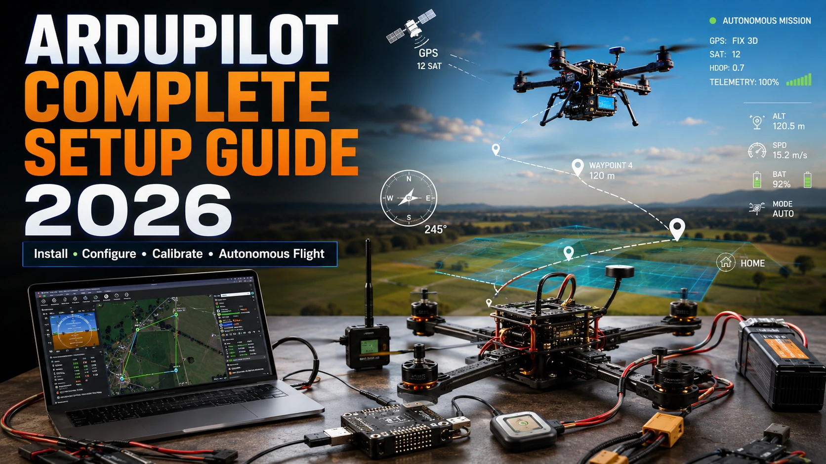
Step-by-step ArduPilot setup guide 2026. Install firmware, configure Mission Planner, calibrate sensors, and fly your first autonomous mission. Beginner to pro.
Introduction
If you have spent any time in the drone industry, you already know the name ArduPilot. But knowing the name and actually knowing how to set it up from scratch that is a very different conversation. This guide bridges that gap completely.
ArduPilot is the world’s most widely used open-source autopilot platform. It runs on everything from a 250-gram racing quad to a 25-kilogram agricultural sprayer. Universities use it for research. Defense contractors use it for development. Survey companies use it for mapping missions. FPV pilots use it for long-range cruising. The platform is mature, incredibly capable, and frankly overwhelming to a newcomer which is exactly why so many people give up during initial setup.
This guide was written by someone who has spent years building and flying ArduPilot systems across multiple vehicle types. The goal is simple: get you from an empty bench to a successful autonomous flight without skipping any of the details that actually matter. If you follow this guide step by step, you will have a properly configured ArduPilot system, a working Mission Planner installation, and the confidence to plan and execute your first autonomous mission.
We cover everything: hardware selection, firmware installation, sensor calibration, flight mode configuration, failsafe setup, telemetry, mission planning, and the pre-flight routine that keeps your aircraft in the air and your test sites intact. We also cover the mistakes beginners make because understanding what goes wrong is just as important as understanding what should go right.
Whether you are a complete beginner who just received a Pixhawk in the mail, an intermediate builder upgrading from a simple flight controller, or an experienced engineer validating a new airframe, there is something here for you.
What is ArduPilot?
A Brief History
ArduPilot started in 2009 as a project by Jordi Muñoz and Chris Anderson, initially built on Arduino hardware — which is where the “Ardu” in the name comes from. What began as a hobbyist experiment to add autopilot capabilities to RC aircraft quickly evolved into one of the most sophisticated open-source flight control systems ever created.
By 2013, the project had outgrown its Arduino roots and the community moved to more powerful hardware. The ArduPilot ecosystem now supports ARM Cortex-based flight controllers with dedicated coprocessors, real-time operating systems, and sensor redundancy far beyond anything the original hardware could handle. The software is maintained by a global community of thousands of developers, with contributions from aerospace engineers, university research labs, and commercial drone manufacturers.
What ArduPilot Actually Does
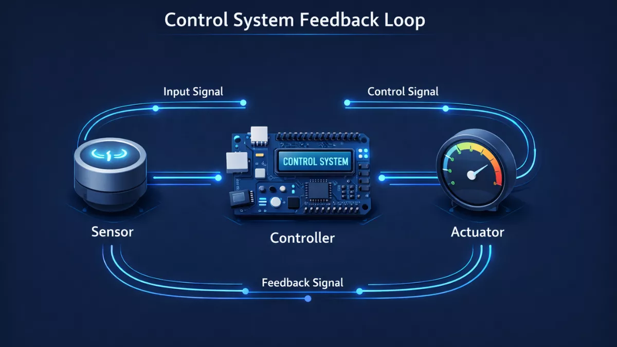
At its core, ArduPilot is firmware — software that runs directly on a flight controller. It reads data from sensors (GPS, accelerometers, gyroscopes, barometer, compass), processes that information through sophisticated filtering algorithms, and sends commands to motors, servos, and other outputs to keep the aircraft stable and on course.
The real power is in what happens beyond basic stabilization. ArduPilot supports fully autonomous missions using waypoints, can execute complex survey patterns, follow moving targets, maintain precise altitude above terrain using digital elevation models, and return home automatically if it loses the RC signal. All of this happens on hardware that can fit in the palm of your hand.
Vehicle Types Supported
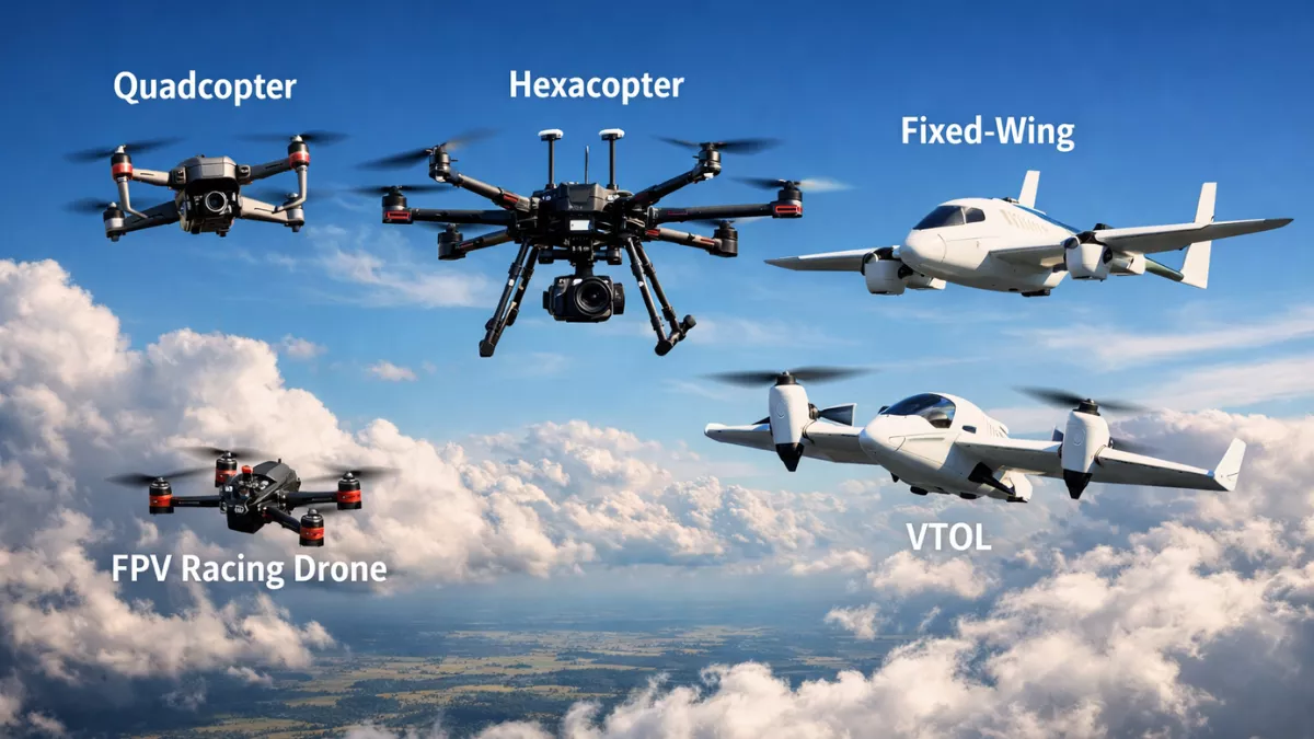
ArduPilot is not just for quadcopters. The platform is organized into separate firmware builds for different vehicle types:
- ArduCopter — Multirotor aircraft (quad, hex, octo, Y6, X8, tricopter, coaxial)
- ArduPlane — Fixed-wing aircraft (conventional, delta wing, flying wing, VTOL)
- ArduRover — Ground vehicles (wheeled and tracked)
- ArduSub — Underwater ROVs and submarines
- ArduBlimp — Airships and lighter-than-air vehicles
- Heli — Traditional and collective pitch helicopters
This guide focuses primarily on multirotor (ArduCopter) and fixed-wing (ArduPlane) setups because they represent the vast majority of real-world use cases, but the configuration principles apply across vehicle types.
The Open-Source Ecosystem
One of ArduPilot’s greatest strengths is that everything is open. The source code is on GitHub. The documentation is community-maintained. Ground control stations, companion computers, and payload controllers can all interface with ArduPilot using the MAVLink communication protocol — an open standard that has become the industry backbone for drone communication.
This openness means you are never locked in. If you want to switch from Mission Planner to QGroundControl, you can. If you want to write custom onboard code running on a Raspberry Pi that sends commands to ArduPilot, the APIs are documented and available. If you find a bug, you can report it — and if you are technically capable, you can fix it yourself and submit the improvement.
Supported Flight Controllers
ArduPilot supports an enormous range of flight controllers. The most common ones you will encounter:
| Controller | Manufacturer | Notes |
|---|---|---|
| Pixhawk 6C / 6X | Holybro | Current generation Pixhawk standard |
| Cube Orange+ | CubePilot | Industrial grade, redundant sensors |
| Cube Black | CubePilot | Previous generation, still widely used |
| F9P/H7 series | Matek | Budget-friendly, good performance |
| F405 / F7 series | SpeedyBee | Popular in FPV-adjacent builds |
| Kakute H7 | Holybro | Compact, AIO designs |
| Pixhawk Mini | Various | Smaller form factor Pixhawk |
For professional applications requiring redundancy and reliability, the CubePilot Cube Orange+ is the current gold standard. For mapping, survey, or high-reliability commercial operations, many operators pair it with a Here3 or Here4 GPS module.
Hardware Requirements
Getting the hardware selection right before you start building saves you significant pain later. Here is what you need and why it matters.
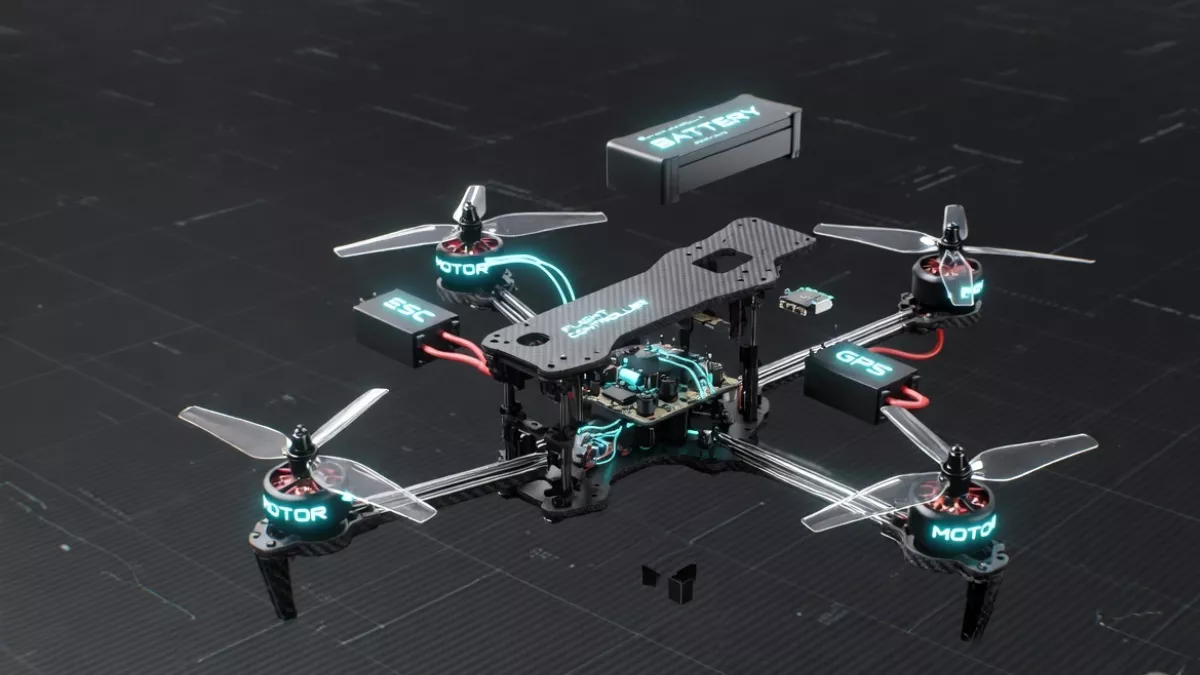
Flight Controller
Your flight controller is the brain of the entire system. It needs to have enough processing power to run ArduPilot smoothly while handling all sensor fusion tasks in real time. For 2026, anything running an STM32H7 processor or better is a solid choice. Older F4-based controllers work but are increasingly limited by processing overhead when running advanced features.
Recommended for beginners: Holybro Pixhawk 6C. Well-documented, widely supported, straightforward pinout, and affordable.
Recommended for professional builds: CubePilot Cube Orange+. The carrier board system gives you flexibility, the triple-redundant IMU gives you safety margin, and the build quality is industrial.
GPS and Compass
For any application that requires position hold, return to launch, or autonomous missions, a quality GPS is non-negotiable. The minimum you should aim for in 2026 is a UBlox M8N-based GPS. For better accuracy and faster lock, the UBlox F9P (RTK capable) is worth the investment in professional applications.
Most ArduPilot GPS modules also include a compass (magnetometer). This compass is critical for heading accuracy, especially in Loiter mode and during autonomous missions. Position the GPS mast as far from the battery and power distribution board as possible — EMI from high-current cables is the number-one cause of compass interference problems.
Recommended GPS modules:
- Holybro H-RTK F9P — Professional RTK, centimeter accuracy
- CubePilot Here4 — Integrated GPS/compass/barometer, CAN bus
- Matek M10-L4-3100 — Budget-friendly, solid performance
- mRo GPS u-Blox Neo-M9N — Mid-range, excellent for most applications
Power Module
The power module serves two functions: it steps down the battery voltage to a regulated 5V for the flight controller, and it measures current and voltage for the battery monitor system. Do not skip this. Flying without current monitoring means flying blind on battery state.
Most Pixhawk-style controllers ship with a basic power module. It works, but the current sense resistor accuracy is mediocre. If you care about precise battery state of charge tracking, the Matek HUBOSD or similar dedicated power monitoring solutions are more accurate.
RC Transmitter and Receiver
ArduPilot works with virtually any RC protocol. In 2026, the recommended protocols are:
- ELRS (ExpressLRS) — Best performance-to-cost ratio, low latency, long range
- FRSky ACCST / ACCESS — Mature ecosystem, good range
- Spektrum DSMX — Common in the US hobbyist market
- TBS Crossfire / Tracer — Long range, popular with fixed-wing
For the radio itself, you need at least 6 channels. Eight channels is comfortable. Ten or more gives you room for auxiliary functions, camera controls, and mode switching without compromise.
ESC and Motors
For multirotor builds, use BLHeli_32 or AM32 ESCs with bidirectional DShot support if your flight controller supports it. DShot provides digital communication between the flight controller and ESC, eliminating the need for ESC calibration and providing RPM telemetry that ArduPilot can use for motor health monitoring.
Motor selection depends entirely on your frame size, propeller diameter, and intended payload. Get a proper thrust calculator (eCalc or similar) and size your motors to provide at least a 2:1 thrust-to-weight ratio at hover throttle around 50%.
Frame
Frame choice matters more than most beginners realize. A rigid, well-built frame keeps vibration low, which directly affects sensor performance. ArduPilot’s EKF (Extended Kalman Filter) is sophisticated, but it cannot compensate for a frame that is vibrating at resonant frequencies through the IMU. Carbon fiber frames are stiffer and lighter. If you use one, make sure your flight controller is on vibration damping mounts (most Pixhawk-style controllers include these).
Software Requirements
Mission Planner
Mission Planner is the primary ground control station (GCS) for ArduPilot on Windows. It is developed by Michael Oborne and maintained by the ArduPilot community. Mission Planner handles everything from firmware installation to parameter configuration, calibration, mission planning, and live telemetry display during flight.
System requirements:
- Windows 10 or Windows 11 (64-bit recommended)
- .NET Framework 4.7.2 or later
- 4 GB RAM minimum (8 GB recommended)
- 2 GB free storage
- USB 2.0 or higher port
On macOS and Linux, QGroundControl is the preferred alternative. It has a different interface but supports the same ArduPilot features through the MAVLink protocol.
Other GCS Options
- QGroundControl — Cross-platform (Windows, macOS, Linux, iOS, Android), modern interface
- APM Planner 2 — Legacy alternative, less actively maintained
- MAVProxy — Command-line GCS, preferred for scripting and companion computer work
- Tower / DroidPlanner — Android-based, useful for field operations
Installing Mission Planner
Step 1: Download
Go to ardupilot.org and navigate to the Mission Planner download page. Always download from the official source. The current stable installer is a standard Windows .msi package.
Step 2: Install
Run the installer with administrator privileges. Accept the default installation directory unless you have a specific reason to change it. The installer includes the Microsoft .NET Framework check — if your system is missing the required version, the installer will prompt you to download it first.
Step 3: Install Drivers
The most common first-hurdle is driver installation. Pixhawk-style controllers typically use one of three USB chipsets:
- STM32 Virtual COM Port — Most Holybro Pixhawk 6C/6X units
- Silicon Labs CP210x — Some older Pixhawk and clone boards
- FTDI FT232R — Some debug adapters and telemetry radios
Mission Planner includes a driver installer accessible under Help > Driver Install. Run this first. If your flight controller still doesn’t appear as a COM port after driver installation, check Device Manager (devmgmt.msc) under Ports (COM & LPT) to see what is and isn’t being recognized.
Troubleshooting Mission Planner Installation
MP won’t open after installation: This is almost always a .NET Framework version issue. Download the .NET 4.8 runtime directly from Microsoft and install it separately.
No COM port appears: Try a different USB cable. This solves the problem about 30% of the time — data-capable cables versus charge-only cables look identical but behave very differently.
MP crashes on startup: Antivirus software sometimes quarantines MP files. Add the Mission Planner installation folder to your antivirus exclusion list.
Installing ArduPilot Firmware
Connecting for the First Flash
Connect your flight controller to your PC via USB before opening Mission Planner. When you open MP, in the top right corner you will see a COM port dropdown and a baud rate dropdown. Set the baud rate to 115200. Do not click Connect yet.
Navigating to Firmware Installation
Go to Setup > Install Firmware. Mission Planner will query the ArduPilot firmware servers and display available vehicle types. You will see icons for:
- ArduCopter (quad, hex, octo, etc.)
- ArduPlane
- ArduRover
- ArduSub
- AntennaTracker
Selecting the Right Firmware
Vehicle type: Choose based on what you are building. For a quadcopter, select the Quad icon under ArduCopter.
Firmware version: Mission Planner defaults to the latest stable release. Unless you have a specific reason to use a beta or development version, stay on stable. Beta firmware may have known issues. Development builds can have unknown ones.
Frame type selection: After firmware flashes, you will be asked to select your frame type (X, Plus, H, etc.). For most quadcopters, this is X-frame configuration.
Flashing the Firmware
Click the vehicle icon. Mission Planner will ask you to confirm, then download and flash the firmware. The process takes about 60–90 seconds. During flashing, the flight controller’s LEDs will blink in a sequence — this is normal. Do not disconnect power or USB during the flash.
Recovery Methods
If a firmware flash fails:
- Try a different USB cable
- Try a different USB port (try a USB 2.0 port instead of USB 3.0)
- Hold the safety button while connecting USB (on some boards this forces DFU boot mode)
- On STM32-based boards, you can use the STM32CubeProgrammer tool directly for recovery
Connecting Your Flight Controller
USB Connection
After firmware is installed, you can now click Connect in Mission Planner. Select the correct COM port from the dropdown (if multiple COM ports appear, the flight controller is typically the highest numbered one), keep baud rate at 115200, and click Connect.
If connection is successful, you will see the artificial horizon on the HUD (Heads Up Display) begin to respond to tilting the flight controller. The parameter download progress bar will appear and complete within a few seconds.
Telemetry Connection
For wireless connection via a SiK telemetry radio (433 MHz or 915 MHz pair):
- Plug the air-side radio into the flight controller’s TELEM1 port
- Plug the ground-side radio into your PC via USB
- In Mission Planner, select the radio’s COM port and set baud rate to 57600
- Click Connect
The radios negotiate automatically. Connection typically takes 5–15 seconds.
WiFi and Bluetooth
Some flight controllers include WiFi or Bluetooth modules that can serve as MAVLink bridges. Configuration varies by module, but the principle is the same — connect to the wireless network or pair the Bluetooth device, then use Mission Planner’s TCP or UDP connection option instead of a serial COM port.
Initial Setup
With Mission Planner connected, navigate to Setup > Mandatory Hardware. This is where the critical configuration happens.
Frame Class and Type
Set your frame class (Quad, Hex, Octo, etc.) and your motor layout (X, Plus, H, V, etc.). This tells ArduPilot which motor outputs correspond to which physical positions and which direction each motor should spin.
Accelerometer Calibration
The accelerometer tells ArduPilot what “level” is and how the aircraft is oriented in space. Calibration is critical — if the accelerometer thinks level is 2 degrees nose-down, your aircraft will try to fly 2 degrees nose-down at all times.
Mission Planner’s accelerometer calibration wizard walks you through placing the aircraft in six orientations:
- Level (flat on a surface)
- Nose down
- Nose up
- Left side down
- Right side down
- On its back (inverted)
Hold each position still until the wizard advances. Use a level surface for the initial flat placement — don’t just eyeball it. A small carpenter’s level costs almost nothing and removes a major source of calibration error.
Compass Calibration
Click Start in the compass calibration section. Pick up the aircraft and rotate it slowly through all orientations — think of tracing a sphere with your drone’s nose. You need to cover all three rotational axes. The calibration completes when enough data points have been collected (shown by the progress bars filling up).
Important: Do compass calibration away from metal objects, computers, and power cables. Calibrate outdoors if possible. A bad compass calibration is one of the most common causes of “toilet bowl effect” in Loiter mode.
After calibration, check the compass offsets. If any offset value exceeds 150–200, your GPS/compass module is suffering significant interference at its mounted location and needs to be repositioned.
Barometer
The barometer calibrates automatically at boot. No manual action required. What you should do is ensure the flight controller is not in direct sunlight and is not subject to airflow during calibration — both cause barometer errors that affect altitude hold accuracy.
Mission Planner Interface Overview
Before going deeper into calibration, it helps to understand the Mission Planner layout so you know where things are.
Top Navigation Bar: FLIGHT DATA | FLIGHT PLAN | INITIAL SETUP | CONFIG | SIMULATION | HELP
FLIGHT DATA — Main HUD display for real-time telemetry, status messages, and sensor readings.
FLIGHT PLAN — Map-based mission editor for waypoints, survey grids, and other autonomous mission types.
INITIAL SETUP — Firmware installation, mandatory hardware calibration, and optional hardware configuration.
CONFIG — Deep parameter access. Everything in Initial Setup is ultimately writing parameters here. Advanced users live in this tab.
SIMULATION (SIM) — Software-in-the-loop (SITL) simulation interface. Practice flying without risking hardware.
HELP — Links to documentation, log files, and driver installation utilities.
Within FLIGHT DATA, the key panels are the HUD (artificial horizon, heading, speed, altitude), the map view, the quick view panel (customizable telemetry values), and the Messages panel at the bottom — which is where pre-arm messages and warnings appear.
Radio Calibration
Before You Begin
Your RC transmitter must be bound to your receiver before starting calibration. The binding process varies by RC protocol and manufacturer consult your transmitter’s manual if you haven’t completed this step.
Calibration Process
- Navigate to Setup > Mandatory Hardware > Radio Calibration
- Turn on your RC transmitter
- Click Calibrate Radio
- Move every stick and switch on your transmitter to its full range — including trims, if you plan to use them
Mission Planner records the minimum and maximum values for each channel. The green bars show the current position of each channel in real time.
Channel Mapping
Standard ArduPilot channel mapping:
- Channel 1: Roll (Aileron)
- Channel 2: Pitch (Elevator)
- Channel 3: Throttle
- Channel 4: Yaw (Rudder)
- Channel 5: Flight Mode (switch)
- Channel 6–8: Auxiliary (camera, gimbal, etc.)
If your transmitter uses Mode 1 (throttle on the right), you may need to adjust channel mapping in your transmitter or in Mission Planner’s parameter tree.
Verifying Stick Direction
After calibration, check that stick inputs move the artificial horizon in the correct direction. Pushing the pitch stick forward (nose down command) should show the horizon rising. Moving roll right should tip the horizon left (you are looking at the aircraft from outside). If anything is reversed, reverse that channel in your transmitter — not in Mission Planner.
ESC Calibration
When You Need ESC Calibration
If you are using analog PWM ESCs, you need to calibrate them so they all have the same throttle range reference. If you are using DShot digital protocol (highly recommended for any modern build), calibration is not required.
Manual Calibration (PWM ESCs)
- Connect all ESCs to the flight controller
- In Mission Planner, navigate to Setup > Optional Hardware > ESC Calibration
- Follow the wizard carefully this involves powering up with full throttle applied, which will spin motors if props are attached. Remove props before calibration.
Automatic Calibration
Mission Planner supports all-at-once calibration through the flight controller. This is safer and faster than manual calibration. The sequence:
- Remove propellers
- Disconnect the flight battery
- Set throttle to full in Mission Planner (or on your transmitter)
- Connect flight battery
- Wait for the ESC arming beeps
- Drop throttle to zero
- Wait for calibration completion beeps
DShot Configuration
For DShot, go to CONFIG and set the MOT_PWM_TYPE parameter to the appropriate DShot value (DShot150, DShot300, or DShot600 depending on your ESC support). Restart the flight controller, and your ESCs are ready without any calibration.
Flight Modes
ArduPilot’s flight modes are one of its most powerful features. Understanding each mode and when to use it is essential for safe operation.
Stabilize
The most basic assisted mode. The flight controller maintains the aircraft’s attitude (roll and pitch angle) but does not hold altitude or position. If you let go of the sticks, the aircraft returns to level flight but will drift with the wind. This is the mode you learn manual flying in.
AltHold (Altitude Hold)
Adds barometric altitude hold on top of Stabilize. The aircraft maintains its current altitude when throttle is at the mid-point. Excellent for getting comfortable before moving to GPS-assisted modes.
Loiter
Full GPS position and altitude hold. This is the “park” mode. Release all sticks and the aircraft holds its position over a fixed GPS coordinate. Wind compensation is active. This is the mode most operators use for video work and inspection.
RTL (Return to Launch)
When triggered, the aircraft climbs to a predefined altitude (RTL_ALT, default 15 meters), flies back to the home point set at arming, loiters above home, then descends and lands. Every ArduPilot build should have RTL configured and tested before any autonomous flight.
Auto
Executes a pre-loaded waypoint mission. The aircraft follows waypoints in sequence, performing commands at each waypoint (photo trigger, hover, altitude change, etc.). This is the mode used for mapping, survey, and inspection missions.
Guided
Allows external control via MAVLink. A companion computer, ground station, or scripting interface can send real-time position targets. Used extensively in research and custom automation applications.
Acro
Rate-based control — stick deflection commands rotation rate rather than angle. No self-leveling. This is the mode for FPV freestyle-style flying. Not recommended until you have significant flight hours in Stabilize.
Circle
The aircraft orbits a point of interest at a configurable radius and speed. Used for cinematic shots and inspection of structures.
Land
Commands immediate descent and landing at the current position. Disarms motors automatically after touchdown detection.
Smart RTL
Like RTL, but instead of flying in a straight line back to home, Smart RTL follows the GPS track of the outbound path in reverse. Useful for avoiding obstacles encountered on the outbound leg.
Configuring Flight Modes
In Mission Planner, go to Setup > Mandatory Hardware > Flight Modes. You will see six flight mode slots, each corresponding to a specific position of your Mode switch. Assign modes logically — a common beginner setup is:
| Switch Position | Mode |
|---|---|
| 1 | Stabilize |
| 2 | AltHold |
| 3 | Loiter |
| 4 | Auto |
| 5 | RTL |
| 6 | Land |
GPS Configuration
Getting GPS Lock
First flight should not happen without GPS lock. A proper GPS lock means the flight controller has received signals from enough satellites to compute a 3D position fix with sufficient accuracy. Mission Planner shows GPS status in the HUD and in the Flight Data status bar.
HDOP (Horizontal Dilution of Precision): This number indicates GPS accuracy. Values below 1.5 are excellent. Values between 1.5 and 2.0 are acceptable. Above 2.0, consider waiting for better satellite geometry.
Minimum satellites: ArduPilot defaults to requiring at least 6 satellites for navigation. In practice, you want 10+ before flying. More satellites mean better position accuracy and faster EKF convergence.
GPS Configuration Parameters
Key GPS parameters in Mission Planner CONFIG tab:
- GPS_TYPE: Set to match your GPS (1 for UBlox auto-detect in most cases)
- GPS_NAVFILTER: Navigation filter setting — leave at default unless you are doing very high-speed flight
- GPS_AUTO_CONFIG: Set to 1 to allow ArduPilot to automatically configure the GPS receiver settings
RTK GPS Setup
For centimeter-level accuracy using RTK:
- The F9P-based GPS requires two units — a rover (on the aircraft) and a base station (on the ground)
- The base station needs to compute its precise position, either through a survey-in process (takes 10–15 minutes) or by entering known coordinates
- RTCM correction data flows from base to rover via telemetry radio
- Mission Planner has built-in RTK support under Initial Setup > Optional Hardware > RTK/GPS Inject
Compass vs GPS Heading
ArduPilot uses the compass for heading at low speeds and during hover. At higher speeds (above approximately 3 m/s), GPS velocity is used to assist or replace compass heading. This is why compass calibration quality matters most for Loiter and slow-speed flight, while GPS quality matters more for mission flying.
Battery Configuration and Monitor Setup
Why Battery Monitoring Matters
Flying until the battery is exhausted is the fastest way to destroy an expensive aircraft. ArduPilot’s battery monitoring system tracks voltage and current in real time, calculates consumed milliamp-hours, and triggers failsafe actions before the battery reaches critical levels.
Wiring the Power Module
Your power module connects between the main battery and the power distribution board. The flight controller connects to the power module’s output connector, which provides both regulated 5V and the voltage/current sense signals.
Configuring in Mission Planner
Navigate to Setup > Optional Hardware > Battery Monitor.
Monitor: Set to “Battery Volts and Current”
Sensor: Select your power module type. If using a generic module, select “Other”
APM Version: Select your flight controller
Voltage Divider and Amperes Per Volt: These are calibration values. Your power module’s datasheet provides these, but they are never perfectly accurate from the factory. For precise current readings, calibrate against a known reference (a power meter like a Watts Up or similar inline meter).
Voltage Calibration
With a multimeter, measure the actual battery voltage at the battery terminals. Compare it to what Mission Planner reports. Adjust the Voltage Divider parameter until the Mission Planner reading matches the multimeter within 0.1V.
Failsafe Voltage Settings
Set these conservatively:
- BATT_LOW_VOLT: The voltage at which the system generates a low battery warning (typically 3.5V per cell × number of cells)
- BATT_CRT_VOLT: The voltage at which emergency land action triggers (typically 3.3V per cell × number of cells)
For a 4S LiPo: Low at 14.0V (3.5V/cell), Critical at 13.2V (3.3V/cell)
Failsafe Setup
Failsafe configuration is not optional. It is the difference between a controlled emergency response and an uncontrolled crash. Take this section seriously.
Radio Failsafe
What happens when the aircraft loses RC signal?
In Mission Planner: Config > Full Parameter List, search for FS_THR_ENABLE.
FS_THR_ENABLE = 1: Enabled — if throttle channel drops below FS_THR_VALUE for more than FS_THR_VALUE_MS, the failsafe triggers.
FS_THR_VALUE: Set this to approximately 10–20 PWM counts below your minimum throttle stick position (typically 975–985 for most RC systems).
Recommended radio failsafe action: RTL. The aircraft returns home and lands. Always verify your home point is an obstacle-free area.
Configure your RC transmitter to output a specific fail-safe value on throttle loss — this is typically in the transmitter’s system menu. Set it to a value that will be recognized by ArduPilot as a signal loss event.
Battery Failsafe
BATT_FS_LOW_ACT: Action at low battery. Recommended: 2 (RTL) BATT_FS_CRT_ACT: Action at critical battery. Recommended: 1 (Land) — at critical level, there may not be enough power to RTL safely
GPS Failsafe
FS_EKF_ACTION: What to do when the EKF (position estimation) quality drops. Recommended: 1 (Land in AltHold) FS_EKF_THRESH: EKF error threshold before failsafe triggers. Default is usually appropriate.
EKF Failsafe
The Extended Kalman Filter is ArduPilot’s sensor fusion core. It constantly monitors its own confidence in the position and attitude estimate. If IMU data, GPS data, and compass data stop agreeing, the EKF will flag an error.
EKF errors before flight are almost always caused by:
- Compass interference from nearby electronics or power cables
- GPS still acquiring lock
- Recent firmware update requiring fresh calibration
Crash Detection
FS_CRASH_CHECK: Enable this (set to 2 for disarm on crash detection). If the aircraft detects the violent attitude changes typical of a crash, it will immediately disarm motors, preventing a propeller from continuing to spin in a pile of wreckage.
Telemetry Setup
SiK Radio Telemetry
The most common ArduPilot telemetry setup uses a pair of SiK-protocol radios — one connected to the flight controller’s TELEM port, one connected to the ground station computer via USB. These are available at 433 MHz (better building penetration, longer range in some conditions) and 915 MHz (required in some regions, generally better throughput).
To configure telemetry radios in Mission Planner, with the ground radio connected, navigate to Initial Setup > Optional Hardware > Sik Radio. Click Load Settings to read the current configuration from both radios. The key parameters:
- Baud: 57600 (standard)
- Air Speed: 64 (higher = faster data, shorter range)
- Net ID: Must match between air and ground radios
- ECC: Error correction — leave enabled
- Encryption: Optional, uses a shared key
4G / LTE Telemetry
For long-range operations beyond line-of-sight (where regulations permit), 4G cellular telemetry provides essentially unlimited range. Options include:
- Holybro μAirLink — Compact, dedicated ArduPilot 4G telemetry
- Raspberry Pi + SIMcom module — DIY companion computer approach
- Herelink — All-in-one 4G video, telemetry, and RC system
For 4G telemetry, MAVLink data flows through a cloud server (ZeroTier, Cloudflare Tunnel, or similar) to reach Mission Planner on the ground. Latency is typically 100–300ms, acceptable for monitoring but not ideal for manual control.
WiFi Telemetry
Useful on the bench and for short-range operations. Some flight controllers include an ESP8266 or ESP32 WiFi module directly. These create a WiFi access point the ground station connects to. Maximum practical range is 100–200 meters with a clear line of sight.
Creating Your First Autonomous Mission
Opening the Flight Planner
Click FLIGHT PLAN in Mission Planner. The map view will load. If you are connected via telemetry, the aircraft’s current GPS position will appear on the map. You can also search for a location using the search bar in the top right.
Setting the Home Point
Right-click on the map where you want to designate as the home position (launch and RTL landing location). Select “Set Home Here.” This point must match your actual takeoff location as closely as possible.
Adding a Takeoff Waypoint
Right-click on the map at your takeoff location and add a TAKEOFF command. Set the altitude (height above the home point) for the initial climb. This is mandatory as the first waypoint in any ArduCopter autonomous mission — you cannot mission fly from ground level.
Adding Waypoints
Left-click on the map to add waypoints. Each waypoint gets a sequence number and default altitude. You can modify the altitude, delay, and commanded action at each waypoint. For a first mission, keep it simple:
- TAKEOFF to 20 meters
- WAYPOINT at Point A (20 meters)
- WAYPOINT at Point B (20 meters)
- WAYPOINT at Point C (20 meters)
- RTL (return home and land)
Survey Grid Mission
For mapping and surveying work, Mission Planner has a built-in Survey Grid tool. Right-click the map and select “Draw Polygon” to define your survey area. Then right-click again and select “Auto WP > Survey (Grid).” Mission Planner will ask for:
- Altitude: Your flight altitude above home
- Overlap: Side and front overlap percentage (70/70 is standard for photogrammetry)
- Camera: Your camera’s sensor specs for accurate footprint calculation
- Angle: Grid line orientation (align with longest dimension of your survey area to minimize turns)
Uploading the Mission
Click Write WPs (Write Waypoints) to upload the mission to the flight controller. The mission is stored in the flight controller’s non-volatile memory you can disconnect and reconnect without losing it. Use Read WPs to verify the mission was received correctly.
First Autonomous Flight Checklist
Never skip the pre-flight checks. An experienced pilot’s checklist looks automatic from the outside, but it is the result of internalizing every failure they or someone they know has experienced.
Day Before the Flight
- [ ] Charge all flight batteries to storage or full charge as appropriate
- [ ] Charge RC transmitter
- [ ] Charge telemetry radios
- [ ] Verify mission loaded in flight controller
- [ ] Check weather forecast
- [ ] Check airspace (use your country’s official drone airspace app — B4UFly in the US, Altitude Angel in the UK, etc.)
- [ ] Identify emergency landing areas at your planned location
At the Field
Aircraft inspection:
- [ ] Frame tight, no loose screws
- [ ] Props secure, no cracks or chips
- [ ] Motors spin freely by hand, no roughness
- [ ] All connectors fully seated
- [ ] All payload/camera mounts secure
- [ ] Nothing loose that could vibrate off
Electronics power-up:
- Connect flight battery (props off at this stage)
- Wait for boot sequence to complete (LED patterns, buzzer tones)
- Connect Mission Planner via telemetry
- Verify all sensors nominal in FLIGHT DATA view
- Verify GPS lock (10+ satellites, HDOP < 1.5)
- Verify compass heading is correct (check against a physical compass)
- Verify battery voltage correct
- Verify no pre-arm errors in Messages panel
Before arming:
- [ ] Area clear of people and obstacles
- [ ] Props installed and secured
- [ ] RC transmitter on and responding
- [ ] Flight mode set to Auto (or Loiter for manual departure)
- [ ] Arm command ready (throttle down-right on most transmitters)
Arming and Takeoff
Arm the motors using the arming gesture or an auxiliary channel configured for arm/disarm. Immediately after arming, verify all motors spin at idle speed. Any motor not spinning, or spinning at a different speed than the others, is a cause to immediately disarm and investigate.
For the first autonomous flight, use a hybrid approach: arm in Stabilize mode, switch to Loiter to verify position hold, then switch to Auto to execute the mission. This gives you a manual override capability at every stage.
After switching to Auto, the aircraft will automatically execute the TAKEOFF command. Stay alert. If anything looks wrong, switching back to Stabilize gives you immediate manual control.
After Landing
- [ ] Disarm immediately after motors stop
- [ ] Wait for props to fully stop before approaching
- [ ] Disconnect flight battery
- [ ] Download and review flight logs (Mission Planner > FLIGHT DATA > Telemetry Logs or DataFlash Logs)
Troubleshooting Common Issues
Pre-Arm Failures
“PreArm: Need 3D Fix” — GPS has not yet acquired a 3D position fix. Wait longer. Move to a location with better sky view.
“PreArm: Compass not calibrated” — Run compass calibration again. Ensure you are away from magnetic interference sources.
“PreArm: Compass offsets too high” — Your compass is experiencing interference at its mounted location. Raise the GPS mast, reroute power cables, or use a magnetically clean mounting location.
“PreArm: RC not calibrated” — Run radio calibration from scratch. Ensure your transmitter is on.
“PreArm: INS not calibrated” — Accelerometer calibration incomplete. Run all six orientation steps again.
“PreArm: EKF variance” — The EKF is not confident in its state estimate. Usually resolves with GPS lock acquisition. If persistent, check compass calibration.
Compass Problems
Toilet bowl effect in Loiter: The aircraft spirals outward slowly instead of holding position. Almost always caused by poor compass calibration or compass interference. Recalibrate outdoors, check mounting location, verify GPS mast height.
Compass inconsistency warning: Multiple compasses disagree. Check COMPASS_EXTERN and COMPASS_ORIENT parameters are correct for your external compass orientation.
GPS Issues
Slow GPS lock: Ensure the GPS has clear sky view. First lock after GPS cold start can take 3–5 minutes. Subsequent locks in the same area are typically under 60 seconds (warm start).
GPS glitch: Sudden GPS position jump. Usually caused by multipath (signal reflection off buildings). Add GPS_GLITCH_RADIUS and GPS_GLITCH_ACCEL parameters to Mission Planner to tune glitch detection sensitivity.
Connection Issues
Mission Planner connects but no telemetry data: Check serial port baud rate matches the parameter settings (SERIAL1_BAUD for TELEM1). Default is 57600.
USB connects but MP shows all zeros: Firmware type mismatch. Ensure you flashed the correct vehicle type and frame configuration.
Motor and ESC Issues
One motor spins differently: ESC calibration not uniform across all ESCs (for PWM). For DShot, check that all ESC firmware is the same version.
Motors spin up randomly before arming: Interference on PWM signal lines. Switch to DShot. If that is not possible, use shielded cables for PWM runs.
Professional Tips and Best Practices
Parameter Backup
Before any significant change, back up your parameters. In Mission Planner, go to CONFIG > Full Parameter List and click Save to File. Name the file with the aircraft name and date. If a firmware update or accidental change corrupts your setup, you can reload the file and restore everything in under a minute.
Flight Log Analysis
ArduPilot generates detailed onboard logs called DataFlash logs. These contain everything: sensor readings, GPS positions, attitude estimates, motor outputs, RC inputs, and EKF data at up to 400Hz. Reviewing these logs after flights is how professional operators catch problems before they cause incidents.
Use Mission Planner’s built-in log review, or better yet, the web-based UAV Log Viewer (plot.ardupilot.org) for easier visualization. Things to check regularly:
- Vibration levels (VIBE.VibeX/Y/Z — should stay below 30 m/s/s)
- EKF variance (EKF5.normInnov values)
- Battery voltage under load (BATT.Volt during full-throttle climbs)
- Compass vs EKF heading deviation
Firmware Update Strategy
Do not update firmware immediately on release day for production systems. Wait 2–3 weeks for the community to report any regressions. For survey operations, maintain a “known good” firmware version and test each update on a bench setup before deploying to production aircraft.
Vibration Management
High vibration is the enemy of accurate sensor fusion. If your VIBE logs show values above 30 m/s/s, take corrective action:
- Balance all propellers
- Check for bent prop adapters
- Ensure motors have no bearing play
- Verify the flight controller is on vibration-dampening mounts
- Check the frame for resonant flex
Pre-Flight Notification and Airspace
Always check airspace before flying. In most jurisdictions, flying without authorization in controlled airspace is a serious regulatory violation. Use official tools not third-party apps that may have outdated data. File NOTAM notifications when required.
Common Beginner Mistakes
1. Calibrating compass indoors. Metal furniture, computer equipment, and building wiring all distort the magnetic field. Always calibrate outdoors, away from vehicles.
2. Not doing a range check. Before any flight, verify your RC system range is adequate. Walk 30 meters away from the aircraft and verify stick inputs are still responsive.
3. Flying with low satellite count. Waiting for “some” GPS lock instead of waiting for adequate GPS lock. Fly with a minimum of 10 satellites and HDOP below 1.5.
4. Not verifying RTL altitude. The default RTL altitude is 15 meters, which is not sufficient in areas with trees or buildings. Set RTL_ALT to a value that clears all obstacles in the home vicinity.
5. Skipping the vibration check. First flights without reviewing vibration logs miss a critical indicator of impending hardware problems.
6. Using a charge-only USB cable. Results in the flight controller not being recognized by the PC and hours of confused troubleshooting.
7. Skipping battery monitor calibration. Results in displayed battery state not matching actual state, increasing the risk of voltage sag causing an in-flight crash.
8. Not testing failsafe before the first autonomous flight. Failsafe is the last line of defense. Test it manually by switching off the transmitter at low altitude in Loiter mode. Verify the aircraft executes RTL.
9. Setting home in the wrong location. If you arm the aircraft indoors or while the GPS is still acquiring lock, the home point may be set incorrectly. Always verify home position on the map after arming.
10. Not removing props during initial setup. During ESC calibration, parameter setup, and radio verification, props should never be on the aircraft. Motors can spin unexpectedly during configuration.
11. Ignoring pre-arm messages. The Messages panel in Mission Planner is showing you exactly what needs attention. Read it. Do not try to force-arm past safety warnings.
12. Flying with default PID tuning on an untested airframe. Default PID values are a starting point. They work acceptably for many builds but may cause oscillations or sluggish response on others. Always tune on your specific airframe.
13. Not setting a battery failsafe. Relying on yourself to notice battery depletion in real time during a mission is unreliable. Let ArduPilot manage it automatically.
14. Flying in Acro mode too early. Acro mode has no self-leveling. Crashing in Acro is extremely fast. Build stick time in Stabilize before considering Acro.
15. Uploading a mission without verifying it. After uploading a mission, use Read WPs to verify every waypoint came through correctly. GPS position conversion errors during upload can send a waypoint to the wrong location.
16. Ignoring compass interference warnings. A compass offset above 200 is a warning that your compass placement is compromised. Fix it before flying, not after.
17. Using old or unknown-source batteries. An aged or counterfeit LiPo can voltage sag dramatically under load, triggering EKF errors, GPS glitches, and uncontrolled descent. Use quality batteries from reputable sources and retire them when capacity drops below 80% of rated.
18. Not reviewing logs after incidents. If anything unusual happens in flight unexpected movement, unexpected landing, brief loss of control download and review the DataFlash logs immediately. The data is there. Use it.
19. Arming in a high-wind location. Wind causes GPS drift between arming and takeoff, which confuses the EKF on early firmware. Always arm in the most wind-sheltered position available.
20. Neglecting post-flight inspection. Motors, props, and frame hardware take stress every flight. Inspect everything after each flight, especially after any hard landing.
Frequently Asked Questions
Q1: What is the difference between ArduCopter and ArduPilot? ArduPilot is the overall project name for the open-source autopilot platform. ArduCopter is the specific firmware within ArduPilot designed for multirotor aircraft (quadcopters, hexacopters, octocopters, etc.). Other vehicle-specific firmwares include ArduPlane (fixed-wing), ArduRover (ground vehicles), and ArduSub (underwater ROVs). When people say “ArduPilot,” they usually mean the ecosystem as a whole.
Q2: Is ArduPilot free to use commercially? Yes. ArduPilot is released under the GNU General Public License (GPL). This means the source code is open and you may use it commercially. However, modifications you make to the core ArduPilot code must be shared if you distribute them. Building products on top of ArduPilot that do not modify the core firmware has fewer restrictions. Always consult the specific license text and a legal advisor for commercial applications.
Q3: Can I use Mission Planner on Mac or Linux? Mission Planner is a Windows-native application. On Mac and Linux, QGroundControl is the recommended alternative. It supports the same ArduPilot functionality through the MAVLink protocol and has a modern, cross-platform interface. MAVProxy is another option for Linux users who prefer a command-line interface.
Q4: How long does the initial setup take? A complete from-scratch setup, including Mission Planner installation, firmware flashing, and all mandatory calibrations, typically takes 2–4 hours for a first-time user. Experienced users can complete it in 30–60 minutes. The most time-consuming parts are compass calibration (getting clean results outdoors) and radio calibration (setting up modes and verifying all channels).
Q5: Do I need RTK GPS for autonomous missions? No. Standard UBlox M8N or M9N GPS provides position accuracy of 1–3 meters, which is adequate for most autonomous missions, surveys, and waypoint navigation. RTK GPS (centimeter-level accuracy) is needed for precision agriculture variable rate application, high-accuracy mapping that will be used directly without GCP correction, or inspection tasks requiring fine positioning above specific structures.
Q6: What is the EKF and why does it matter? EKF stands for Extended Kalman Filter. It is ArduPilot’s sensor fusion algorithm that combines data from the IMU (accelerometers and gyroscopes), GPS, barometer, compass, and optionally optical flow and rangefinders to produce an accurate real-time estimate of the aircraft’s position, velocity, and attitude. The EKF constantly assesses its own confidence. If sensor data becomes inconsistent, the EKF raises warnings and can trigger failsafe actions. A healthy EKF is fundamental to stable autonomous flight.
Q7: How do I know if my compass is interfering with nearby electronics? After compass calibration, check the compass offsets in Mission Planner (CONFIG > Full Parameter List, search COMPASS_OFS). If any offset value (X, Y, or Z for any compass) exceeds 200, your compass is experiencing significant magnetic interference at its mounted location. Try raising the GPS/compass mast, moving power cables away from the compass, and recalibrating.
Q8: Can ArduPilot fly without GPS? Yes, but with reduced capability. Without GPS, you are limited to non-position-hold modes: Stabilize, AltHold, and Acro. Loiter, RTL, Auto, and other GPS-dependent modes require a GPS fix. Optical flow sensors can provide position hold capability in GPS-denied environments but require careful setup and calibration.
Q9: What is MAVLink? MAVLink (Micro Air Vehicle Link) is the communication protocol that ArduPilot uses to exchange telemetry, commands, and status information between the flight controller and ground control stations, companion computers, and other systems. It is a lightweight, binary protocol designed for low-bandwidth connections. MAVLink is the reason you can use any compliant GCS (Mission Planner, QGroundControl, etc.) with ArduPilot.
Q10: How many waypoints can a mission have? This depends on the flight controller’s memory. Most modern Pixhawk-type controllers support 750–1000 waypoints. For large survey missions with more waypoints than the controller can hold, Mission Planner can split missions into segments and upload them sequentially.
Q11: What is the difference between Loiter and Position Hold? In ArduPilot terminology for multirotors, these terms are often used interchangeably. Loiter uses GPS to hold both horizontal position and altitude. The aircraft actively compensates for wind drift. Position Hold is a similar concept on some manufacturers’ flight controllers. In ArduPilot specifically, Loiter is the standard GPS position hold mode.
Q12: How do I update ArduPilot firmware without losing my configuration? Before updating, export your current parameters: CONFIG > Full Parameter List > Save to File. After updating firmware, re-run all mandatory calibrations (accelerometer and compass) because firmware updates can change sensor calibration storage. Then load your parameter file and check that critical settings were correctly restored. Not all parameters restore correctly across major version updates.
Q13: Can ArduPilot work with a tablet or smartphone as a ground station? Yes. QGroundControl has Android and iOS apps that work as full ground control stations via WiFi or Bluetooth telemetry. Tower (DroidPlanner) is another Android option specifically for ArduPilot. These are useful in the field but most operators still prefer a laptop for mission planning and detailed configuration.
Q14: What does “Stabilize” mode do differently from “AltHold”? In Stabilize, the throttle stick directly controls motor output — there is no altitude compensation. Releasing the throttle to center will cause the aircraft to descend. In AltHold, the throttle stick controls climb/descent rate from a center position. At center throttle, the barometer-based altitude hold activates. AltHold is significantly easier to fly, especially for beginners.
Q15: How do I set up a geofence in ArduPilot? Mission Planner supports geofencing through the Fence menu in Flight Plan. You can define a circular fence around the home point (FENCE_RADIUS) or a polygon fence using the polygon drawing tool. When the aircraft approaches or crosses the fence boundary, ArduPilot can trigger an RTL. Enable fencing under Config > Geofence, setting FENCE_ENABLE to 1 and FENCE_ACTION to your desired response.
Q16: What is HDOP and what value is acceptable? HDOP (Horizontal Dilution of Precision) is a measure of how well satellite geometry contributes to horizontal position accuracy. Lower values are better. For autonomous flight, target HDOP below 1.5. Values between 1.5 and 2.0 are acceptable for most operations. Above 2.0, positional accuracy degrades to the point where Loiter performance and waypoint accuracy suffer noticeably.
Q17: Can I use ArduPilot for FPV racing? ArduPilot is primarily designed for autonomous and assisted-flight applications rather than FPV racing. For pure racing, Betaflight or EmuFlight offer faster PID loop times and features tailored to racing. That said, ArduPilot’s Acro mode is capable and some long-range FPV fliers specifically choose ArduPilot for its sophisticated failsafe, telemetry, and return-to-home capabilities.
Q18: What is the difference between ArduPilot stable and beta firmware? Stable firmware releases are tested versions considered safe for normal operation. Beta firmware contains new features and bug fixes that have passed initial testing but may have unresolved issues. Development (master) builds are the bleeding edge and should only be used by developers and advanced testers. For any operational aircraft, always use stable unless you have a specific tested need for a beta feature.
Q19: How do I configure a gimbal with ArduPilot? ArduPilot supports both simple servo gimbals and digital gimbals using MAVLink (DJI Ronin, Gremsy, etc.). For servo gimbals, configure output channels under Optional Hardware > Camera Gimbal. Set the input and output channels, mount type, and stabilization modes. For MAVLink gimbals, enable the MNT_TYPE parameter to match your gimbal protocol. ArduPilot can stabilize gimbal tilt, roll, and pan axes.
Q20: What parameters should I check if the aircraft drifts in Loiter? First verify GPS quality (satellite count and HDOP). Then check compass calibration quality and look for interference signs (high compass offsets). Review EKF innovation data in DataFlash logs. Check that INS_GYRO_FILTER and INS_ACCEL_FILTER are at appropriate values for your IMU. Excessive vibration also degrades Loiter performance — verify vibration levels are below 30 m/s/s on all axes.
Q21: Can ArduPilot do terrain following? Yes. ArduPilot supports terrain following using either a downloaded SRTM terrain database (available in Mission Planner) or real-time rangefinder data. In terrain following mode, the aircraft maintains a constant height above ground rather than above sea level. This is essential for survey and inspection in hilly terrain. Enable with TERRAIN_ENABLE and set your terrain database in Mission Planner.
Q22: What is the maximum range for autonomous missions? There is no software-enforced range limit in ArduPilot beyond geofence settings you configure. The practical range limit is determined by your telemetry and RC control range and your regulatory permissions. Beyond visual line of sight (BVLOS) operations require specific regulatory authorizations in virtually every country.
Q23: How do I enable optical flow for GPS-denied flight? Connect your optical flow sensor (PX4Flow, Matek 3901-L0X, etc.) to the appropriate serial or I2C port. Set FLOW_TYPE to match your sensor. Set EK3_SRC1_VELXY and EK3_SRC1_POSZ parameters to use optical flow as the velocity source. A downward-facing rangefinder is required alongside optical flow for altitude hold in GPS-denied flight.
Q24: What is the best way to learn ArduPilot if I am completely new? Start with ArduPilot’s SITL (Software In The Loop) simulation. This runs the real ArduPilot firmware on your PC without needing hardware. You can fly missions, test failsafes, and practice mode switching in a simulated environment. Mission Planner includes a built-in SITL interface under the Simulation tab. After SITL, move to simple flights in Stabilize mode before progressing to autonomous modes.
Q25: Why does my aircraft climb or dive when I switch to Auto mode? The first waypoint altitude in your mission differs significantly from your current altitude. ArduPilot in Auto mode will try to reach the first waypoint’s altitude immediately. Always ensure your TAKEOFF waypoint is the first command, and set a reasonable initial altitude. Review all waypoint altitudes before upload to ensure they make sense relative to your launch altitude.
Conclusion
ArduPilot is one of the most powerful tools in the unmanned systems world, and you now have a complete reference for setting it up correctly. From selecting hardware through to executing a fully autonomous mission, every stage has been covered here with the kind of practical detail that actually helps in the field.
The honest truth about ArduPilot is that the learning curve is real but not impossibly steep. The documentation is extensive, the community is active, and the platform rewards the effort you put into understanding it. Every hour spent reading parameters, reviewing logs, and testing systems in a controlled environment is an hour that makes your actual flight operations safer and more reliable.
A few things to carry forward: never skip the pre-flight checks, always verify your failsafe functions before relying on them, and treat every DataFlash log as a source of learning. The most experienced ArduPilot operators are not the ones who have flown the most missions without incident they are the ones who have studied their logs carefully enough to prevent incidents from happening.
Your next steps after completing this guide: spend time in SITL simulation before committing to hardware. Fly extensively in Stabilize before transitioning to autonomous modes. Start with simple missions and add complexity progressively. Join the ArduPilot forums and Discuss community the collective knowledge there is extraordinary.
Fly safely, follow your local regulations, and remember that an aircraft that lands predictably is worth more than one that is pushed beyond its proven envelope.
Want to Explore More? Setting Up Your Drone Programming Development Environment: The Complete Guide
Mr. Raj Kumar is a highly experienced Technical Content Engineer with 7 years of dedicated expertise in the intricate field of embedded systems. At Embedded Prep, Raj is at the forefront of creating and curating high-quality technical content designed to educate and empower aspiring and seasoned professionals in the embedded domain.
Throughout his career, Raj has honed a unique skill set that bridges the gap between deep technical understanding and effective communication. His work encompasses a wide range of educational materials, including in-depth tutorials, practical guides, course modules, and insightful articles focused on embedded hardware and software solutions. He possesses a strong grasp of embedded architectures, microcontrollers, real-time operating systems (RTOS), firmware development, and various communication protocols relevant to the embedded industry.
Raj is adept at collaborating closely with subject matter experts, engineers, and instructional designers to ensure the accuracy, completeness, and pedagogical effectiveness of the content. His meticulous attention to detail and commitment to clarity are instrumental in transforming complex embedded concepts into easily digestible and engaging learning experiences. At Embedded Prep, he plays a crucial role in building a robust knowledge base that helps learners master the complexities of embedded technologies.