Microcontroller vs Microprocessor vs SoC : Whether you’re a beginner stepping into embedded systems or an experienced engineer brushing up on core concepts, understanding the difference between a Microcontroller (MCU), Microprocessor (MPU), and System on Chip (SoC) is crucial. These are the brains behind every smart gadget—from your smartwatch to a satellite!
In this post, we’ll break it down simply with clear definitions, use cases, and a side-by-side comparison.
Microcontroller vs Microprocessor vs SoC
What is a Microcontroller (MCU)?
A Microcontroller is a compact integrated circuit designed to perform a specific control task in embedded systems.
Key Features:
Includes CPU + RAM + ROM + I/O peripherals on a single chip
Meant for real-time control
Low power, cost-effective
Runs simple firmware or embedded applications
Use Cases:
Washing machines, microwave ovens
Wearables like fitness trackers
Automotive dashboard systems
Arduino-based hobby projects
Note: Microcontrollers are ideal for small, low-power, task-specific systems.
What is a Microprocessor (MPU)?
A Microprocessor is a general-purpose CPU integrated into a single chip, but without built-in memory or peripherals.
Key Features:
Just the CPU
Needs external RAM, ROM, I/O
Designed for high performance and complex computing
Used in general-purpose computing
Use Cases:
Personal computers
Servers
Laptops
Desktop applications
Note : Microprocessors power general computing systems requiring external memory and peripherals.
What is a System on Chip (SoC)?
A System on Chip combines all components of a computer—CPU, GPU, RAM, storage, wireless modules, and I/O—on a single chip.
Key Features:
Combines MCU/MPU + peripherals + connectivity
Compact and power-efficient
Highly integrated
Custom-built for specific devices
Use Cases:
Smartphones and tablets
IoT devices
Smart TVs
Raspberry Pi
✅ Note : SoCs are the powerhouse of modern smart devices combining performance and efficiency.
Quick Comparison Table onMicrocontroller vs Microprocessor vs SoC
Feature
Microcontroller (MCU)
Microprocessor (MPU)
System on Chip (SoC)
Integration
CPU + RAM + ROM + I/O
CPU only
CPU + GPU + Memory + I/O
Application Type
Specific tasks (real-time)
General computing
Versatile, integrated systems
Cost & Power
Low
Higher
Medium to low
Performance
Moderate
High
High
Memory
Built-in
External
Built-in
Typical Use
Embedded devices
Computers, servers
Smartphones, IoT, tablets
Conclusion for Microcontroller vs Microprocessor vs SoC
Understanding the difference between a Microcontroller, Microprocessor, and SoC helps you pick the right solution for your embedded project or product. Here’s a quick rule of thumb:
🧩 Use MCU when you need low cost, low power, and a focused task
💻 Use MPU when you need high computation with external resources
📱 Use SoC when you want an all-in-one compact powerhouse
Follow-up interview questions Interviewer might askonMicrocontroller vs Microprocessor vs SoC
🔧 Microcontroller-Specific Questions:
Can you name a few popular microcontrollers you’ve worked with?
What are the advantages of using an MCU in real-time embedded systems?
How do you program a microcontroller, and which tools have you used?
What’s the difference between Harvard and Von Neumann architecture in the context of MCUs?
🖥️ Microprocessor-Focused Questions:
Why would you choose a microprocessor over a microcontroller in a design?
How do you handle memory management in systems using microprocessors?
What kind of operating systems typically run on microprocessor-based systems?
📱 SoC-Related Questions:
Can you give an example of a SoC you’ve worked with and what peripherals it included?
What challenges have you faced while developing software for SoCs?
How do SoCs support power optimization in battery-powered devices?
🤖 System Design and Application:
Suppose you have to design a smart home device. Will you choose an MCU, MPU, or SoC? Why?
Have you worked on bare-metal programming or RTOS on any MCU? Explain.
What are the criteria you consider while selecting between MCU, MPU, or SoC for an embedded product?
🧠 Conceptual or Deep-Dive Questions:
How does interrupt handling differ in MCUs vs MPUs?
Explain the boot process for an SoC-based system.
What’s the role of MMU in a microprocessor, and is it present in microcontrollers?
Can you compare an SoC running Android vs an MPU running embedded Linux?
You can also Visit other tutorials of Embedded Prep
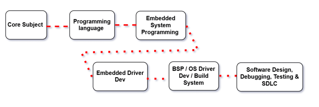
Embedded Software Roadmap is a clear, step-by-step guide for beginners and professionals who want to build a strong career in embedded systems.
Are you eager to dive into the world ofembedded systems but don’t know where to start? This beginner-friendly roadmap will guide you step-by-step, from basic concepts to real-time projects, helping you build a strong foundation and become a successful embedded software engineer in 2025.
Embedded Software Roadmap
Step 1: Master the Core Subjects of Embedded Systems
1.1 Digital Electronics
Digital Electronics is the foundation of modern computing and embedded systems. It harnesses the power of binary logic—0s and 1s—to design systems that are precise, reliable, and scalable. As the first step in the Embedded Software Roadmap, mastering digital electronics is essential. From microprocessors to embedded controllers, digital electronics enables the creation of intelligent hardware through logic gates, Boolean algebra, and state-driven systems. This knowledge sets the stage for developing efficient and robust embedded software.
At its core, digital electronics replaces analog ambiguity with digital precision, making it the heart of systems like communication devices, automation units, robotics, and consumer electronics. By combining combinational and sequential circuits, engineers can design everything from simple adders to complex programmable logic devices like FPGAs.
With digital design, we build the brains of technology—machines that think, decide, and act based on logic and encoded instructions. It’s not just about electronics—it’s about empowering innovation through logical architecture.
Understand how electronic signals represent data:
Number systems: Binary, Hexadecimal, BCD
Logic Gates: AND, OR, NOT, NAND, NOR, XOR
Flip-Flops and Registers
Combinational vs Sequential Circuits
Multiplexers, Encoders, Decoders
Popular Microcontrollers to Explore:
AVR: ATmega328P (used in Arduino)
ARM: STM32, ESP32, nRF52
1.2 Operating Systems (OS)
Digital Electronics is the foundation of modern computing and embedded systems. It harnesses the power of binary logic—0s and 1s—to design systems that are precise, reliable, and scalable. As the first step in the Embedded Software Roadmap, mastering digital electronics is essential. From microprocessors to embedded controllers, digital electronics enables the creation of intelligent hardware through logic gates, Boolean algebra, and state-driven systems. This knowledge sets the stage for developing efficient and robust embedded software.
As we move forward in theEmbedded Software Roadmap, we encounter the critical role of Operating Systems.
An Operating System (OS) is the unseen force that transforms hardware into a functional and responsive digital environment. Acting as the central coordinator, it manages everything—from running applications and allocating memory to handling user input and controlling hardware components.
It provides an abstraction layer, allowing developers and users to interact with complex machines through simple, intuitive interfaces. Whether it’s scheduling tasks, managing filesystems, or ensuring secure multitasking, the OS silently enforces structure and efficiency beneath every click and tap.
From real-time embedded platforms like FreeRTOS, QNX, and VxWorks to general-purpose systems like Linux, Windows, and macOS, Operating Systems are not just software—they are digital ecosystems that balance performance, reliability, and usability.
Why it’s important: Many embedded systems run on RTOS (like FreeRTOS, VxWorks) or Embedded Linux. Understanding OS concepts helps you manage processes, memory, and scheduling efficiently.
Topics to Cover:
Process vs Thread
Memory Management (Heap, Stack, Paging)
CPU Scheduling Algorithms
Interprocess Communication (IPC): semaphores, mutex, pipes
Real-Time Operating Systems (RTOS): concepts of tasks, preemption, priority inversion
Embedded Linux basics: init system, daemons, file system layout
1.3 Computer Architecture
Computer Architecture defines the conceptual design and operational framework of a computer system. It is the strategic art of organizing hardware components and establishing how they interact to execute instructions efficiently and reliably.
In the Embedded Software Roadmap, understanding computer architecture is a critical step—especially for developers working close to the hardware. This architectural blueprint includes the internal structure of the CPU—such as the control unit, ALU, and registers—as well as memory hierarchy, I/O mechanisms, and instruction sets. It governs how software communicates with hardware, how data moves through the system, and how performance can be improved using techniques like pipelining, caching, and parallel processing.
Why it matters: Embedded development often involves bare-metal programming, writing assembly code, or optimizing C/C++ for resource-constrained environments. A solid grasp of computer architecture empowers developers to write efficient code, debug at the hardware level, and fine-tune performance for real-time applications.
In essence, computer architecture transforms raw silicon into a purposeful computing engine—balancing speed, power, and scalability to meet the demands of modern embedded systems..
Topics to Cover:
Instruction Set Architecture (ISA): RISC vs CISC
ARM Cortex-M and ARMv7 architecture
Registers, ALU, Control Unit
Pipelining and hazards
Caches (L1/L2), memory hierarchy
Memory-mapped I/O
Endianness
1.4 Computer Networks
As embedded systems evolve, connectivity becomes increasingly vital. Computer Networks form the backbone of modern communication, enabling devices to share data, resources, and services—whether they’re part of a smart home, a vehicle, or a global cloud infrastructure.
In the Embedded Software Roadmap, understanding computer networks is crucial for building connected and intelligent embedded systems. Networks are built on layered protocols, starting from physical connections and data link layers to higher-level transport and application services. These layers work together to define how information is packaged, transmitted, routed, and received reliably and securely.
From wired LANs in industrial automation to wireless technologies powering IoT ecosystems, networks allow embedded devices to interact in real-time, share sensor data, receive firmware updates, and integrate with cloud platforms.
Why it’s important: Many modern embedded systems are no longer standalone. Devices often operate as part of a larger connected environment, making it essential to understand networking protocols like TCP/IP, UDP, MQTT, HTTP, and Bluetooth. This knowledge allows developers to implement secure, scalable, and efficient communication in embedded applications.
More than just infrastructure, computer networks serve as the digital nervous system of embedded and IoT applications—ensuring smooth, synchronized, and intelligent operations across distributed systems.
Topics to Cover:
OSI Model and TCP/IP
IP, UDP, TCP – Packet structures, handshakes
HTTP/HTTPS protocols
MQTT and CoAP (for IoT)
Bluetooth, Wi-Fi, ZigBee (basic wireless comm.)
Socket programming basics
Step 2: Master the Programming Language
At the heart of embedded software development lies programming languages—tools that transform ideas into functional systems. In the Embedded Software Roadmap, mastering the right programming languages is a fundamental step. These languages enable developers to write efficient, optimized code that directly controls hardware and processes data in real-time.
For embedded systems, C and C++ are the most widely used languages due to their efficiency, low-level hardware access, and performance. C is often preferred for bare-metal development because it allows precise control over system resources, while C++ introduces object-oriented features that enhance code structure, maintainability, and scalability.
In addition to C/C++, many embedded developers also explore Python for higher-level tasks like testing, automation, and scripting, as well as Assembly for low-level performance tuning. Understanding these languages provides the flexibility to tackle various embedded development challenges, whether you’re programming microcontrollers, designing device drivers, or developing real-time applications.
Why it’s important: Mastery of these languages allows embedded engineers to write efficient, low-level code that interacts directly with hardware, ensuring fast execution and minimal resource consumption. Additionally, knowledge of object-oriented programming in C++ supports building modular and maintainable systems, which is crucial for complex embedded projects.
In essence, mastering programming languages empowers embedded software engineers to translate hardware requirements into functional code—balancing performance, resource utilization, and reliability in every line of code.
2.1 Start with Embedded C Programming
Why C? C is the de facto standard for embedded development because of its:
Low-level access to memory (pointers)
Speed and minimal overhead
Hardware-level register manipulation
Portability across microcontrollers
Topics to Master in C:
Basics:
Data types (uint8_t, uint16_t, etc. from <stdint.h>)
Operators, Control flow, Functions
Intermediate:
Pointers, Arrays, Strings
Bitwise operations (|, &, ^, ~, <<, >>)
Structs, Enums, Typedef
Header files and Modular programming
Makefiles and Compilation
Advanced:
Memory management: Stack vs Heap
const, volatile, static, extern
Inline functions, Macros, Preprocessor directives
Interrupt Service Routines (ISRs) in C
Working with hardware registers (*(volatile uint32_t*)0x40021000 = 0x01;)
Category
Topics
Notes / Relevance
Basics of C
Introduction to C
Data Types, Variables, Constants
Operators: Arithmetic, Relational, Logical, Bitwise, Assignment
Expressions & Precedence
Input/Output functions (printf, scanf)
Comments & Coding Standards
Foundation for Embedded C programming
Control Statements
if, if-else, nested if
switch-case
Loops: for, while, do-while
break, continue, goto statements
Essential for program flow and decision-making
Functions
Function declaration & definition
Parameter passing: by value, by reference
Recursion
Inline functions
Library functions & custom headers
Code modularity and reusability in embedded projects
Arrays & Strings
Single & Multidimensional arrays
String handling & manipulation
Memory considerations in embedded systems
Used for data storage and sensor/memory interfacing
Pointers & Memory Management
Pointer basics & arithmetic
Pointers with arrays, strings, and functions
Dynamic memory allocation: malloc, calloc, free
Memory-mapped I/O in embedded systems
Critical for efficient memory use and hardware interfacing
Structures & Unions
struct declaration & usage
Nested structs
Union & enum usage
Bit-fields for memory optimization
Typedef usage
Used for organizing sensor data, registers, and peripherals
Direct MCU programming and real-time embedded applications
File Handling & EEPROM/Flash
File handling in C (for RTOS/host environment)
Reading/writing persistent memory
EEPROM/Flash interfacing
Persistent storage for embedded systems
Advanced Embedded C Concepts
Memory alignment & padding
Inline assembly in C
Using const, static, extern effectively
Real-Time Operating System (RTOS) integration basics
Modular programming & header/source file structure
Advanced control over performance, memory, and RTOS integration
Debugging & Testing
Using GDB for embedded systems
Unit testing with Google Test or Ceedling
Using serial debugging (UART)
LED and buzzer debugging
Watchpoints, breakpoints, and logging
Critical for reliable embedded software development
Step 2.1: C++
Once you’ve got a handle on C, it’s time to go deeper into C++, which is widely used in automotive, RTOS-based, and IoT embedded systems.
a)Learn Basic C++
Keywords: basic C++ tutorial, C++ syntax, C++ for beginners
Start with the fundamentals:
Data types & variables
Conditionals and loops
Functions and recursion
Arrays and strings
Pointers and references
Dynamic memory (new, delete)
Namespaces, inline functions, function overloading
🎯 Practice via platforms like LeetCode, HackerRank, or using mini console-based apps.
b) Understand OOPs Concepts
In the world of embedded software development, Object-Oriented Programming (OOP) is a powerful design paradigm that structures code around real-world entities. Instead of focusing solely on procedures or functions, OOP organizes software into objects—modular, reusable units that encapsulate both data and behavior. This approach makes the code more intuitive, maintainable, and scalable.
In the Embedded Software Roadmap, understanding OOP concepts like encapsulation, inheritance, polymorphism, and abstraction is essential for developing robust embedded systems, especially as applications grow in complexity. By focusing on what things are (objects) and what they do (methods), developers can model real-world systems more naturally, improving both code readability and flexibility.
Why it’s important: For embedded systems, OOP allows you to write cleaner, more organized code. It enables better reuse of software components, which can be critical when developing complex systems with limited resources. By applying OOP principles, embedded developers can design more scalable and maintainable systems, while also reducing errors and simplifying debugging.
In essence, mastering OOP in embedded software development provides the tools to design systems that are not only functional but also easier to manage and extend over time—ensuring long-term efficiency and adaptability.
Object-Oriented Programming is what gives C++ its real power.
Classes and Objects
Encapsulation, Abstraction
Inheritance (single, multiple, hybrid)
Polymorphism (compile-time & runtime)
Constructors and Destructors
this pointer, friend functions, operator overloading
const, static, virtual, pure virtual functions
Note: In embedded, avoid dynamic memory allocation and deep inheritance trees.
c)Learn STL (Standard Template Library)
The Standard Template Library (STL) is a powerful feature of C++ that brings the elegance of generic programming to everyday development. It offers a rich set of predefined classes and functions—ready to manage data structures and algorithms with optimal efficiency and minimal effort.
STL is useful even in high-end embedded systems or while writing test utilities.
Iterators: Input, Output, Forward, Bidirectional, Random access
Function Objects & Lambda Expressions
Templates: Function and class templates
d)Practice DSA (Data Structures & Algorithms)
Data Structures and Algorithms (DSA) form the strategic core of software development, providing the tools and techniques needed to organize data and solve problems efficiently. While data structures define how information is stored, algorithms dictate the logic to process and transform it.
From managing dynamic memory with linked lists and trees to optimizing decisions through sorting, searching, and graph traversal, DSA equips developers to think critically and code smartly. It transforms brute-force solutions into optimized, scalable approaches—essential in everything from system design to real-time applications.
Mastering DSA isn’t just about writing code—it’s about developing a problem-solving mindset that balances time, space, and logic to build high-performance software in the real world.
Embedded engineers may not need complex DSA every day, but knowing it improves problem-solving and code quality.
🎯 Practice on Codeforces, LeetCode, and GeeksforGeeks.
💛 Support Embedded Prep
If you find our tutorials helpful and want to support our mission of sharing high-quality embedded system knowledge, you can contribute by buying us a coffee.
Every small contribution helps us keep creating valuable content for learners like you. ☕
Thank you for your support — it truly keeps Embedded Prep growing. 💻✨
e)Build a C++ Project Using Qt
Creating a C++ project with Qt is the perfect fusion of high-performance backend logic and a powerful cross-platform GUI framework. Qt empowers developers to bring their C++ code to life with intuitive interfaces, event-driven programming, and modular architecture.
In this approach, core functionality is implemented using the robustness of C++, while Qt handles the presentation layer through its flexible widgets, signals and slots mechanism, and UI design tools. Whether it’s a data visualization dashboard, a custom tool, or a real-time system monitor, Qt makes it easy to integrate rich user experiences with efficient native code.
Building a project with Qt not only sharpens object-oriented programming skills but also teaches practical concepts like multi-threading, event handling, resource management, and cross-platform deployment—all in a unified development environment.
Qt is widely used in embedded GUIs (especially for infotainment, industrial devices, dashboards).
Steps:
Install Qt Creator and set up a CMake-based project
Learn Qt Widgets or QML for UI
Connect buttons, sliders, and sensors using signals and slots
Use multithreading with QThread or QtConcurrent
Integrate serial communication with QSerialPort (to talk to microcontrollers)
Home automation GUI to control ESP32/Arduino via serial
🛠 Bonus: Try to cross-compile the Qt app for ARM/Linux target (e.g., Raspberry Pi or BeagleBone).on bare-metal safe subsets.
2.3 Assembly Language (Bonus)
Assembly Language is the closest human-readable form of programming that directly interacts with a system’s hardware. It acts as a thin layer between machine code and high-level programming, providing fine-grained control over a processor’s operations.
Each instruction in Assembly corresponds to a single machine-level command, allowing developers to manipulate registers, memory addresses, I/O ports, and control flow with exact precision. This low-level access makes Assembly indispensable for performance-critical, time-sensitive, and resource-constrained environments such as embedded systems, operating systems, and device drivers.
Learning Assembly Language offers deep insights into CPU architecture, instruction sets, and how software translates into actual machine operations. It is not just a programming tool—it’s a window into the very core of computing.
When ultra-precise control is needed:
Learn basic ARM Cortex-M Assembly (or AVR)
Understand registers, stack frames
Learn how to optimize critical sections
2.4 Python for Embedded Automation and Tools
Python has become an indispensable tool in the embedded systems world, offering a high-level language that enhances productivity while maintaining the low-level precision required for embedded automation. By leveraging Python in embedded environments, developers can rapidly prototype, automate processes, and streamline toolchains without sacrificing performance.
Python excels in creating custom automation scripts, interacting with hardware interfaces, and building tooling that simplifies development workflows. Whether it’s controlling GPIO pins, interfacing with sensors, or automating testing procedures, Python brings simplicity and flexibility to embedded systems, making tasks like data logging, hardware testing, and system monitoring much more efficient.
With libraries such as RPi.GPIO, PySerial, and PyTest, Python enables seamless integration between embedded platforms and the tools used for development, testing, and debugging. It’s the perfect language for rapid development and automation, bridging the gap between embedded hardware and sophisticated software control.
Python isn’t usually used directly on MCUs but is great for:
Writing test scripts for embedded hardware
Serial communication (pyserial)
Parsing logs, files, and test reports
GUI with Tkinter or PyQt
Data plotting with matplotlib
Embedded Use Cases:
Automate firmware flashing over USB/UART
Data logger scripts
Backend control panel for IoT devices
Unit test automation
2.5 Shell Scripting (Bash) for Embedded Linux
Shell scripting, particularly with Bash, is a powerful and flexible tool for managing and automating tasks in Embedded Linux environments. It allows developers to streamline system administration, automate device configurations, and control the boot process—all through simple, concise commands.
In the realm of embedded systems, Bash scripts serve as the bridge between hardware and software, facilitating tasks like system startup configuration, file manipulation, hardware diagnostics, and process management. The efficiency of Bash lies in its ability to manipulate files, manage system resources, and interact with the Linux kernel—all without needing to write complex C code.
A must-have for embedded Linux developers:
Basics: if, for, while, variables, functions
File operations, logging, redirections
Using grep, awk, sed, cut
Automate build, flash, and deploy pipelines
Write scripts to configure GPIO, I2C, or SPI on Linux boards
Used heavily in Yocto, Buildroot, init scripts, and service management.
Step 3: Systems Programming and Embedded Driver Development with ARM Cortex M3/M4
Note : To gain a deeper understanding of Systems Programming on ARM Cortex-M3/M4 MPU, it is highly recommended to engage in hands-on practical exercises
Communication Protocol
I2C
SPI
UART / USART
I2S
TC/IP
UDP
Ethernet
CAN
LIN
BT / WIFI / USB
Note : For an in-depth understanding, consider mastering microcontroller development with a focus on embedded driver development, including I2C, GPIO, USART, timers, PWM, CAN, RTC, STM32-LTDC, LCD-TFT, and LVGL.
Popular MCUs to practice:
Atmega328p (Arduino Uno)
STM32F103, STM32F4 series
ESP32 (for Wi-Fi + BLE)
NXP, Renesas, TI MCUs
Complete Electronics Core Topics Every Embedded Software Engineer Must Know (ECE/EEE)
Category
Topics
Notes / Relevance
Basic Electrical & Electronics
Voltage, Current, Resistance, Power, Energy
Ohm’s Law & Kirchhoff’s Laws
Series & Parallel Circuits
AC & DC Fundamentals, RMS & Peak values
Passive Components: Resistors, Capacitors, Inductors
Semiconductors: Diodes, LEDs, BJTs, MOSFETs
Voltage dividers, RC/RL/RLC circuits
Foundation for understanding circuits and embedded interfacing
Special thanks to @mr-raj for contributing to this article on Embedded Prep
Important Embedded C Questions
S.No
Question
1
What is embedded C?
2
What is an embedded system?
3
Differentiate between a microprocessor and a microcontroller.
4
Explain the various data types in C used for embedded systems.
5
What are the basic differences between C and embedded C?
6
How do you declare a constant in embedded C?
7
What is the keyword “volatile” used for in embedded C?
8
Explain the difference between static and dynamic memory allocation in embedded C.
9
What is an interrupt and how is it handled in embedded C?
10
Explain the concept of polling versus interrupt-driven I/O.
11
How do you perform bitwise operations in embedded C?
12
Describe the process of creating a delay in embedded C.
13
What is the significance of the “restrict” keyword in embedded C?
14
Explain the purpose of the “const” keyword in embedded C.
15
How do you declare and use a pointer in embedded C?
16
What is a structure in embedded C and how is it used?
17
Describe the role of the “typedef” keyword in embedded C.
18
Explain the concept of bit fields in embedded C.
19
What is a union and how is it used in embedded C?
20
What are the advantages of using bit manipulation in embedded C?
21
Describe the “volatile” keyword and its importance in embedded C.
22
Explain the concept of portability in embedded C programming.
23
How do you implement a circular buffer in embedded C?
24
What is the difference between little-endian and big-endian byte ordering in embedded systems?
25
How do you implement a finite state machine in embedded C?
26
Describe the process of handling errors in embedded C programming.
27
Explain the role of the linker in embedded C programming.
28
What is the significance of the “extern” keyword in embedded C?
29
How do you perform input/output operations in embedded C?
30
Describe the concept of real-time operating systems (RTOS) in embedded C.
31
How do you handle multi-threading in embedded C?
32
What is the purpose of the “inline” keyword in embedded C?
33
Explain the concept of interrupt latency in embedded systems.
34
How do you implement a watchdog timer in embedded C?
35
Describe the process of programming timers in embedded C.
36
What are the different types of memory available in embedded systems?
37
How do you perform memory-mapped I/O in embedded C?
38
Explain the concept of DMA (Direct Memory Access) in embedded systems.
39
How do you handle endianness issues in embedded C?
40
Describe the process of implementing a software stack in embedded C.
41
What is the role of a bootloader in embedded systems?
42
How do you debug embedded C code?
43
Explain the concept of cache memory and its impact on embedded systems.
44
How do you handle floating-point arithmetic in embedded C?
45
Describe the process of implementing a communication protocol in embedded C.
46
What is the role of the startup code in embedded systems?
47
How do you perform memory alignment in embedded C?
48
Explain the concept of memory-mapped peripherals in embedded systems.
49
How do you handle power management in embedded C?
50
Describe the process of implementing a state machine in embedded C.
51
What is a pointer-to-function in embedded C?
52
How do you perform code optimization in embedded C?
53
Explain the concept of real-time scheduling in embedded systems.
54
How do you implement a circular linked list in embedded C?
55
Describe the process of implementing a hardware driver in embedded C.
56
What is the role of the stack pointer in embedded systems?
57
How do you perform memory pooling in embedded C?
58
Explain the concept of hardware-software co-design in embedded systems.
59
How do you handle multi-tasking in embedded C?
60
Describe the process of implementing a state transition table in embedded C.
61
What is the role of the program counter in embedded systems?
62
How do you perform fixed-point arithmetic in embedded C?
63
Explain the concept of real-time constraints in embedded systems.
64
How do you implement a priority queue in embedded C?
65
Describe the process of implementing a device driver in embedded C.
66
What is the role of the status register in embedded systems?
67
How do you perform memory-mapped file I/O in embedded C?
68
Explain the concept of multi-core processing in embedded systems.
69
How do you handle concurrency issues in embedded C?
70
Describe the process of implementing a message passing mechanism in embedded C.
71
What is the role of the interrupt vector table in embedded systems?
72
How do you perform fixed-size memory allocation in embedded C?
73
Explain the concept of real-time task synchronization in embedded systems.
74
How do you implement a priority-based scheduler in embedded C?
75
Describe the process of implementing a file system in embedded C.
76
What is the role of the system control register in embedded systems?
77
How do you perform memory-mapped I/O with direct addressing in embedded C?
78
Explain the concept of hardware acceleration in embedded systems.
79
How do you handle resource contention in embedded C?
80
Describe the process of implementing a power management scheme in embedded C.
81
What is the role of the interrupt service routine in embedded systems?
82
How do you perform dynamic memory allocation in embedded C?
83
Explain the concept of real-time task synchronization using semaphores in embedded systems.
84
How do you implement a round-robin scheduler in embedded C?
85
Describe the process of implementing a communication protocol stack in embedded C.
86
What is the role of the memory management unit in embedded systems?
87
How do you perform memory-mapped I/O with indirect addressing in embedded C?
88
Explain the concept of hardware/software partitioning in embedded systems.
89
How do you handle inter-process communication in embedded C?
90
Describe the process of implementing a real-time operating system kernel in embedded C.
91
What is the role of the system timer in embedded systems?
92
How do you perform memory-mapped I/O with bank switching in embedded C?
93
Explain the concept of hardware verification in embedded systems.
94
How do you handle synchronization issues in embedded C?
95
Describe the process of implementing a memory management scheme in embedded C.
96
What is the role of the interrupt controller in embedded systems?
97
How do you perform memory-mapped I/O with memory-mapped registers in embedded C?
98
Explain the concept of hardware-in-the-loop testing in embedded systems.
99
How do you handle real-time constraints in embedded C?
100
Describe the process of implementing a task scheduler in embedded C.
101
What is the role of the watchdog timer in embedded systems?
102
How do you perform memory-mapped I/O with memory-mapped files in embedded C?
103
Explain the concept of hardware debugging in embedded systems.
104
How do you handle exception handling in embedded C?
105
Describe the process of implementing a device driver framework in embedded C.
106
What is the role of the reset vector in embedded systems?
107
How do you perform memory-mapped I/O with memory-mapped peripherals in embedded C?
108
Explain the concept of hardware emulation in embedded systems.
109
How do you handle real-time task synchronization using message queues in embedded C?
110
Describe the process of implementing a real-time scheduler in embedded C.
111
What is the role of the memory protection unit in embedded systems?
112
How do you perform memory-mapped I/O with memory-mapped ports in embedded C?
113
Explain the concept of hardware co-simulation in embedded systems.
114
How do you handle real-time task synchronization using event flags in embedded C?
115
Describe the process of implementing a fault-tolerant system in embedded C.
116
What is the role of the power management unit in embedded systems?
117
How do you perform memory-mapped I/O with memory-mapped devices in embedded C?
118
Explain the concept of hardware validation in embedded systems.
119
How do you handle real-time task synchronization using mutexes in embedded C?
120
Describe the process of implementing a real-time communication protocol in embedded C.
121
What is the role of the memory controller in embedded systems?
122
How do you perform memory-mapped I/O with memory-mapped buffers in embedded C?
123
Explain the concept of hardware synthesis in embedded systems.
124
How do you handle real-time task synchronization using condition variables in embedded C?
125
Describe the process of implementing a real-time file system in embedded C.
126
What is the role of the peripheral controller in embedded systems?
127
How do you perform memory-mapped I/O with memory-mapped displays in embedded C?
128
Explain the concept of hardware modelling in embedded systems.
129
How do you handle real-time task synchronization using semaphores and priority inversion in embedded C?
130
Describe the process of implementing a real-time network stack in embedded C.
131
What is the role of the DMA controller in embedded systems?
132
How do you perform memory-mapped I/O with memory-mapped sensors in embedded C?
133
Explain the concept of hardware simulation in embedded systems.
134
How do you handle real-time task synchronization using spinlocks in embedded C?
135
Describe the process of implementing a real-time file system journal in embedded C.
136
What is the role of the interrupt controller in embedded systems?
137
How do you perform memory-mapped I/O with memory-mapped timers in embedded C?
138
Explain the concept of hardware acceleration using FPGA in embedded systems.
139
How do you handle real-time task synchronization using priority inheritance in embedded C?
140
Describe the process of implementing a real-time memory management scheme in embedded C.
141
What is the role of the interrupt vector table in embedded systems?
142
How do you perform memory-mapped I/O with memory-mapped ADCs in embedded C?
143
Explain the concept of hardware co-design using high-level synthesis in embedded systems.
144
How do you handle real-time task synchronization using priority ceiling protocol in embedded C?
145
Describe the process of implementing a real-time communication protocol stack in embedded C.
146
What is the role of the system timer in embedded systems?
147
How do you perform memory-mapped I/O with memory-mapped DACs in embedded C?
148
Explain the concept of hardware-in-the-loop testing using virtual prototypes in embedded systems.
149
How do you handle real-time task synchronization using reader-writer locks in embedded C?
150
Describe the process of implementing a real-time fault-tolerant system in embedded C.
151
What is the role of the watchdog timer in embedded systems?
152
How do you perform memory-mapped I/O with memory-mapped PWMs in embedded C?
153
Explain the concept of hardware debugging using JTAG in embedded systems.
154
How do you handle real-time task synchronization using priority ceiling emulation in embedded C?
155
Describe the process of implementing a real-time virtual file system in embedded C.
156
What is the role of the reset vector in embedded systems?
157
How do you perform memory-mapped I/O with memory-mapped UARTs in embedded C?
158
Explain the concept of hardware emulation using virtual platforms in embedded systems.
159
How do you handle real-time task synchronization using message-passing rendezvous in embedded C?
160
Describe the process of implementing a real-time distributed system in embedded C.
161
What is the role of the memory protection unit in embedded systems?
162
How do you perform memory-mapped I/O with memory-mapped SPIs in embedded C?
163
Explain the concept of hardware co-simulation using System C in embedded systems.
164
How do you handle real-time task synchronization using priority-based spinlocks in embedded C?
165
Describe the process of implementing a real-time fault-tolerant communication protocol in embedded C.
166
What is the role of the power management unit in embedded systems?
167
How do you perform memory-mapped I/O with memory-mapped I2Cs in embedded C?
168
Explain the concept of hardware validation using formal methods in embedded systems.
169
How do you handle real-time task synchronization using priority-based semaphores in embedded C?
170
Describe the process of implementing a real-time secure file system in embedded C.
171
What is the role of the memory controller in embedded systems?
172
How do you perform memory-mapped I/O with memory-mapped GPIOs in embedded C?
173
Explain the concept of hardware synthesis using high-level languages in embedded systems.
174
How do you handle real-time task synchronization using priority-based condition variables in embedded C?
175
Describe the process of implementing a real-time embedded database system in embedded C.
176
What is the role of the peripheral controller in embedded systems?
177
How do you perform memory-mapped I/O with memory-mapped PWMs in embedded C?
178
Explain the concept of hardware modeling using hardware description languages in embedded systems.
179
How do you handle real-time task synchronization using priority-based mutexes in embedded C?
180
Describe the process of implementing a real-time secure communication protocol stack in embedded C.
181
What is the role of the DMA controller in embedded systems?
182
How do you perform memory-mapped I/O with memory-mapped UARTs in embedded C?
183
Explain the concept of hardware acceleration using GPU in embedded systems.
184
How do you handle real-time task synchronization using priority-based reader-writer locks in embedded C?
185
Describe the process of implementing a real-time embedded web server in embedded C.
186
What is the role of the interrupt controller in embedded systems?
187
How do you perform memory-mapped I/O with memory-mapped SPIs in embedded C?
188
Explain the concept of hardware co-design using IP cores in embedded systems.
189
How do you handle real-time task synchronization using priority-based rendezvous in embedded C?
190
Describe the process of implementing a real-time distributed communication protocol stack in embedded C.
1. What is embedded software?
Embedded software is a specialized type of software designed to run on hardware devices like microcontrollers, sensors, or boards such as Arduino, STM32, or Raspberry Pi. It controls specific functions within a larger system, often in real-time.
2. Is this roadmap suitable for complete beginners?
Yes! This roadmap is designed for absolute beginners with no prior experience in embedded systems. Whether you’re a student or a career switcher, you’ll find easy-to-follow steps, project ideas, and learning paths.
3.Do I need to know C or C++ to get started?
Knowing C is highly recommended, as it’s the foundation of embedded programming. However, our roadmap starts from scratch and will guide you to learn C and eventually C++ at a comfortable pace.
4.What hardware do I need as a beginner?
You can start with basic, affordable boards like: Arduino Uno ESP32 or ESP8266 (for IoT projects) STM32 (for advanced learning) These boards are beginner-friendly and widely supported by tutorials.
5.Do I need electronics knowledge to start embedded programming?
Only basic electronics knowledge is needed. The roadmap includes beginner-friendly explanations of resistors, capacitors, GPIOs, sensors, and circuits with diagrams and examples.
6.Can I follow this roadmap while working or studying full-time?
Absolutely! The guide is broken down into Step wise milestones, so you can learn at your own pace — even if you have just a few hours per week.
7.What tools and software are covered in the roadmap?
You’ll learn how to use: Arduino IDE PlatformIO STM32CubeIDE QEMU (for emulation) Git & GitHub Linux terminal basics GCC compiler and Makefiles
8.Does the roadmap include real-world projects?
Yes! You’ll work on practical projects like: LED blinking Temperature & humidity monitor IoT gas alert system Audio player with amplifier Real-time sensor dashboard with Python and web interface
9.Is Linux knowledge required?
Basic Linux knowledge is helpful but not mandatory. The roadmap includes a beginner section to get you comfortable with Linux commands, scripting, and embedded Linux fundamentals.
10.What’s the goal of this roadmap?
The roadmap aims to help you: ✅ Build a strong foundation in embedded systems ✅ Learn to work with real hardware ✅ Understand drivers, RTOS, and protocols ✅ Create portfolio-worthy projects ✅ Prepare for embedded job interviews
11.Where can I find the full roadmap?
The complete guide is available on our website/blog: Embedded Prep Master – Make sure to bookmark it and follow us for updates!
You can also Visit other tutorials of Embedded Prep
Bubble Sort Algorithm: Bubble Sort is one of the most fundamental and widely recognized sorting algorithms in computer science. Its simplicity and educational value make it a popular choice for introducing beginners to the concept of algorithmic thinking and sorting mechanisms. Though not the most efficient for large datasets, Bubble Sort’s step-by-step operation provides an excellent foundation for understanding how comparison-based sorting works.
Bubble Sort Key Features
In-place sorting algorithm
Stable sorting technique
Works in O(n²) time complexity
Best sorting algorithm for small data sets
Bubble Sort Algorithm Explained
Bubble Sort goes through the list, swapping neighboring elements that are out of order, and keeps repeating this process until the entire list is sorted.
How does bubble sort work ?
Start from the beginning of the array
Compare each pair of adjacent elements
If two neighboring elements aren’t in the correct order, simply swap them to move closer to the desired sequence.
Repeat until no swaps are needed
Bubble Sort Code in C
#include <stdio.h>

void bubbleSort(int arr[], int n) {
    for (int i = 0; i < n - 1; i++) {
        for (int j = 0; j < n - i - 1; j++) {
            if (arr[j] > arr[j + 1]) {
                // Swap
                int temp = arr[j];
                arr[j] = arr[j + 1];
                arr[j + 1] = temp;
            }
        }
    }
}
Bubble Sort Code in C++
#include <iostream>
using namespace std;

void bubbleSort(int arr[], int n) {
    for (int i = 0; i < n - 1; i++) {
        for (int j = 0; j < n - i - 1; j++) {
            if (arr[j] > arr[j + 1]) {
                swap(arr[j], arr[j + 1]);
            }
        }
    }
}
What is the best case time complexity of bubble sort?
Case
Time Complexity
Best Case
O(n)
Average Case
O(n²)
Worst Case
O(n²)
Space Complexity: O(1) – No extra space used
Best for educational purposes, interview preparation, and embedded systems sorting problems
Can bubble sorter used in alphabetical order?
we can compare strings using comparison operators like > or <, or use string comparison functions depending on the programming language.
Exmaple in C
#include <iostream>
#include <string>
using namespace std;

void bubbleSort(string arr[], int n) {
    for (int i = 0; i < n-1; ++i) {
        for (int j = 0; j < n-i-1; ++j) {
            if (arr[j] > arr[j+1]) {
                // Swap if out of order
                string temp = arr[j];
                arr[j] = arr[j+1];
                arr[j+1] = temp;
            }
        }
    }
}

int main() {
    string names[] = {"banana", "apple", "grape", "cherry"};
    int n = sizeof(names)/sizeof(names[0]);

    bubbleSort(names, n);

    cout << "Sorted names:\n";
    for (int i = 0; i < n; ++i)
        cout << names[i] << endl;

    return 0;
}
Can bubble sort be used for descending order ?
Bubble sort can be easily modified to sort in descending order by just changing the comparison condition.
Key Difference:
Ascending order: if (arr[j] > arr[j+1])
Descending order: if (arr[j] < arr[j+1])
Example: Descending Order (C++)
#include <iostream>
using namespace std;

void bubbleSortDescending(int arr[], int n) {
    for (int i = 0; i < n - 1; ++i) {
        for (int j = 0; j < n - i - 1; ++j) {
            if (arr[j] < arr[j + 1]) {
                // Swap for descending order
                int temp = arr[j];
                arr[j] = arr[j + 1];
                arr[j + 1] = temp;
            }
        }
    }
}

int main() {
    int numbers[] = {10, 4, 7, 1, 9};
    int n = sizeof(numbers) / sizeof(numbers[0]);

    bubbleSortDescending(numbers, n);

    cout << "Sorted in descending order:\n";
    for (int i = 0; i < n; ++i)
        cout << numbers[i] << " ";

    return 0;
}
Output:
Sorted in descending order:
10 9 7 4 1
You can do the same thing with strings for reverse alphabetical order:
if (arr[j] < arr[j+1]) // for strings
Benefits of Bubble Sort
Easy to implement
Perfect for beginner programmers
Helps understand the concept of element swapping and iteration
Frequently asked in coding interviews and technical exams
Applications of Bubble Sort
Embedded software systems
Microcontroller data sorting
Sorting sensor values
Small dataset processing in IoT
💛 Support Embedded Prep
If you find our tutorials helpful and want to support our mission of sharing high-quality embedded system knowledge, you can contribute by buying us a coffee.
Every small contribution helps us keep creating valuable content for learners like you. ☕
Thank you for your support — it truly keeps Embedded Prep growing. 💻✨
Final Thoughts
Use Bubble Sort to master the basics of sorting algorithms. With its simple logic and straightforward code, it’s ideal for learning, teaching, and solving real-world problems in C and C++.
What is Bubble Sort in C and C++
Bubble Sort is a simple sorting algorithm used in C and C++ that repeatedly compares and swaps adjacent elements if they are in the wrong order. It continues this process until the entire array is sorted in ascending or descending order.
Why is it called Bubble Sort?
It’s called Bubble Sort because the largest (or smallest) elements “bubble up” to the end (or beginning) of the array after each iteration, just like bubbles rising to the surface of water.
Can I use Bubble Sort for large datasets?
While Bubble Sort works for small arrays, it is inefficient for large datasets due to its O(n²) time complexity. For larger datasets, more advanced algorithms like Quick Sort or Merge Sort are recommended.
Is Bubble Sort stable and in-place?
Yes, Bubble Sort is a stable sorting algorithm (it maintains the order of equal elements) and it is in-place, meaning it does not require extra memory space.
You can also Visit other tutorials of Embedded Prep
If you’re diving into sorting algorithms, the selection sort algorithm is one of the simplest and most intuitive methods to start with. Despite being basic, it’s a great way to understand the fundamentals of sorting logic. In this blog post, we’ll walk through what selection sort is, how it works, its time complexity, and a sample code in C++.
What is selection sort ?
What is selection sort : Selection sort is a kind of sorting method based on comparisons technique. It separates the array into a sorted parts and an unsorted parts, then repeatedly selects the smallest element from the unsorted parts and places it at the end of the sorted parts
How the Selection Sort Algorithm Works
Here’s a step-by-step working techinuque of selection sort explanation:
Start from the first element of the array.
Search the smallest element in the unsorted portion.
Swap the smallest element with the first element.
Shift the dividing line between the sorted and unsorted parts one position forward (next).
Repeat until the array is sorted.
Example of Selection Sort Algorithm
Let’s say we have an below array:
[45, 22, 89, 33, 10]
How selection sort works ?
Let’s gone through below steps how selection sort would organize it:
First, examine the entire list [45, 22, 89, 33, 10]. The smallest value is 10. Swap it with the first element 45 → [10, 22, 89, 33, 45]
Next, look at the subarray [22, 89, 33, 45]. The smallest number is 22, which is already in place. No swap needed.
Now move to [89, 33, 45]. The minimum here is 33. Swap it with 89 → [10, 22, 33, 89, 45]
Then, in [89, 45], the smallest is 45. Swap it with 89 → [10, 22, 33, 45, 89]
The array is now sorted using selection sort algorithm.
Is selection sort stable ?
Selection sort is stable or not : Selection Sort is inherently unstable — but not because it swaps elements, rather because it does not respect the original order of equivalent elements when finding the minimum.
Let’s reimagine this through a theater analogy:
Imagine you’re organizing people (elements) by height (value) for a stage performance. You always pick the shortest person (minimum) and move them to the front — but without caring whether two people of the same height had different roles (original positions). You just swap whoever is found first in your search, even if it pushes someone with an earlier role to the back.
So in essence:
Selection Sort does not maintain “role memory” for equal values.
It simply grabs the minimum, regardless of earlier appearances.
This causes instability, because if two equal elements are separated by a swap, the relative order is broken.
However — and here’s the twist Google doesn’t tell you:
Selection Sort can be made stable with a simple tweak: instead of swapping, insert the minimum in-place while shifting others to the right.
But that tweak costs performance. So while basic Selection Sort is not stable, a thoughtful rewrite can make it so, at the cost of efficiency.so now we able to understand why selection sort is not stable .
What is selection sort in c ++?
#include <iostream>
using namespace std;

void selectionSort(int arr[], int n) {
    for (int i = 0; i < n - 1; i++) {
        int minIdx = i;

        for (int j = i + 1; j < n; j++) {
            if (arr[j] < arr[minIdx])
                minIdx = j;
        }

        swap(arr[minIdx], arr[i]);
    }
}

void printArray(int arr[], int size) {
    for (int i = 0; i < size; i++)
        cout << arr[i] << " ";
    cout << endl;
}

int main() {
    int arr[] = {45,22,89,33,10};
    int n = sizeof(arr) / sizeof(arr[0]);

    cout << "Original array of array is : ";
    printArray(arr, n);

    selectionSort(arr, n);

    cout << "Sorted array: ";
    printArray(arr, n);

    return 0;
}
Output :
💛 Support Embedded Prep
If you find our tutorials helpful and want to support our mission of sharing high-quality embedded system knowledge, you can contribute by buying us a coffee.
Every small contribution helps us keep creating valuable content for learners like you. ☕
Thank you for your support — it truly keeps Embedded Prep growing. 💻✨
What is the best case and worst case complexity of selection sort ?
Case
Time Complexity
Best case
O(n²)
Avg case
O(n²)
Worst case
O(n²)
Space Complexity: O(1) Because selection sort sorts elements directly within the original array, it maintains a constant space complexity throughout the process.
What is selection sort in c ?
#include <stdio.h>

int digitSum(int n) {
    int sum = 0;
    while(n) {
        sum += n % 10;
        n /= 10;
    }
    return sum;
}

void selectionSortByDigitSum(int arr[], int n) {
    for(int i = 0; i < n - 1; i++) {
        int min = i;
        for(int j = i + 1; j < n; j++) {
            if(digitSum(arr[j]) < digitSum(arr[min])) {
                min = j;
            }
        }
        int temp = arr[i];
        arr[i] = arr[min];
        arr[min] = temp;
    }
}

int main() {
    int arr[] = {91, 34, 23, 82, 17};
    int n = sizeof(arr)/sizeof(arr[0]);

    selectionSortByDigitSum(arr, n);

    for(int i = 0; i < n; i++)
        printf("%d ", arr[i]);

    return 0;
}
When to Choose Selection Sort?
Selection sort may not be the most efficient option for large datasets, but it excels in the following scenarios:
Simple to grasp
Ideal for small arrays
Excellent for teaching and learning purposes
Conclusion
The selection sort algorithm is a simple yet powerful concept that helps build a strong foundation in sorting logic. Though it’s not the fastest for large arrays, its ease of implementation and step-by-step nature make it ideal for beginners.
Thank you for exploring Selection sort algorithm tutorials ! Stay ahead in embedded systems with expert insights, hands-on projects, and in-depth guides. Follow Embedded Prep for the latest trends, best practices, and step-by-step tutorials to enhance your expertise. Keep learning, keep innovating!
What is Selection Sort?
Answer: Selection Sort is a simple sorting algorithm that works by repeatedly finding the smallest element and swapping it with the current element.
How does Selection Sort work?
Answer: The algorithm divides the array into two parts: sorted and unsorted. It selects the minimum element from the unsorted part and swaps it with the leftmost unsorted element.
What is the time complexity of Selection Sort?
Answer: The time complexity of Selection Sort is O(n^2) in all cases (best, worst, and average).
Is Selection Sort stable?
Answer: No, Selection Sort is not a stable sorting algorithm, as it may change the relative order of equal elements.
You can also Visit other tutorials of Embedded Prep
Merge sort algorithm:Sorting is a fundamental concept in computer science, and one of the most efficient and widely used sorting techniques is Merge Sort. Whether you’re preparing for coding interviews or building real-world software, understanding Merge Sort can boost your algorithmic thinking.
What is Merge Sort?
Merge Sort is a divide-and-conquer algorithm that works by breaking down a list into smaller chunks, sorting those pieces individually, and then merging them back together in the correct order. It’s known for its reliable performance, even with large datasets.
Key Characteristics:
Stable Sort: Maintains the relative order of equal elements.
Time Complexity: O(n log n) in all cases (best, average, worst).
Space Complexity: O(n) due to the temporary arrays used for merging.
How Does Merge Sort Work?
Imagine you have a messy pile of cards. Instead of sorting them all at once, you divide them into smaller piles, sort each pile, and then combine the sorted piles into one organized deck. Merge Sort does exactly that, but with numbers (or any sortable data).
Step-by-Step Process:
Divide the array into two halves.
Recursively sort each half.
Merge the sorted halves into a single sorted array.
Sorting plays a crucial role in organizing data efficiently. Among the various algorithms, Merge Sort stands out for its efficiency and reliability. Let’s break it down in the simplest way possible.
Example
Let’s say you have the following array:
[38, 27, 43, 3, 9, 82, 10]
Your goal is to sort this array in ascending order using Merge Sort.
Step-by-step:
Divide: Split the array until each part has a single element: [38] [27] [43] [3] [9] [82] [10]
Sort and Merge:
Merge [38] and [27] → [27, 38]
Merge [27, 38] and [43] → [27, 38, 43]
Merge [3] and [9] → [3, 9], then merge with [82] → [3, 9, 82], and finally merge with [10] → [3, 9, 10, 82]
Final Merge: Merge [27, 38, 43] and [3, 9, 10, 82] → [3, 9, 10, 27, 38, 43, 82]
Intuition
Imagine you are sorting playing cards. It’s easier to sort two small piles and then combine them than to sort a large pile all at once. That’s what Merge Sort does.
It divides the problem into smaller sub-problems.
Solves each smaller problem (sorts each half).
Then combines the solutions (merges sorted halves).
This divide-and-conquer strategy makes Merge Sort powerful and predictable.
Approach
Merge Sort follows a recursive strategy:
Divide the array into two halves.
Recursively apply merge sort to each half.
Merge the two sorted halves into one.
Key Points:
Uses extra space (temporary arrays).
Always has time complexity of O(n log n).
Performs well with large datasets and linked lists.
Pseudocode
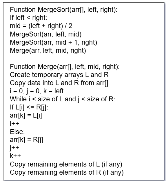
Here’s the simplified pseudocode for Merge Sort:
Merge Sort Pseudocode
What’s the Goal?
We want to take an unsorted array and sort it in ascending order. Merge Sort does this by splitting the array, sorting the parts, and then merging them.
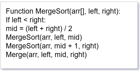
MergeSort(arr, left, right)
Explanation:
arr[] – This is the array we want to sort.
left – The starting index of the array.
right – The ending index of the array.
Step-by-step:
If left is smaller than right, it means we still have more than one element in the array.
Find the middle point (to divide the array into two halves).
Recursively sort the first half.
Recursively sort the second half.
Merge the two sorted halves.
It keeps calling itself (recursion) until each half has only one element. That’s when sorting begins.
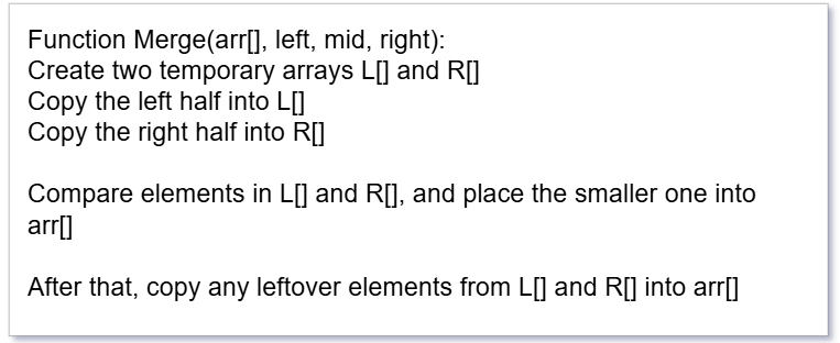
Merge(arr, left, mid, right)
Explanation:
This function merges two already sorted halves of the array into one sorted array.
Step-by-step:
Make two temporary arrays – one for the left part and one for the right part.
Copy elements from the original array into these two parts.
Start comparing the first elements from both halves:
Put the smaller one back into the original array.
Keep comparing and placing until one of the arrays is empty.
If anything is left over in L or R, just copy it into the original array.
💛 Support Embedded Prep
If you find our tutorials helpful and want to support our mission of sharing high-quality embedded system knowledge, you can contribute by buying us a coffee.
Every small contribution helps us keep creating valuable content for learners like you. ☕
Thank you for your support — it truly keeps Embedded Prep growing. 💻✨
Real-Life Analogy
Think of Merge Sort like sorting pages of a book:
You split the book in half.
Ask two people to sort each half separately.
Then you take both sorted stacks and combine them one page at a time in the correct order.
Visual Example
Suppose we want to sort the array: [38, 27, 43, 3, 9, 82, 10]
Split into two halves: [38, 27, 43] and [3, 9, 82, 10]
Keep splitting until you reach single-element arrays:
[38] [27] [43] [3] [9] [82] [10]
Merge step-by-step:
[27, 38], [3, 43], [9, 10], [9, 10, 82]
Final result: [3, 9, 10, 27, 38, 43, 82]
Merge Sort in Java
public class MergeSort {
    public static void mergeSort(int[] arr, int left, int right) {
        if (left < right) {
            int mid = (left + right) / 2;

            mergeSort(arr, left, mid);
            mergeSort(arr, mid + 1, right);

            merge(arr, left, mid, right);
        }
    }

    public static void merge(int[] arr, int left, int mid, int right) {
        int n1 = mid - left + 1;
        int n2 = right - mid;

        int[] L = new int[n1];
        int[] R = new int[n2];

        for (int i = 0; i < n1; i++)
            L[i] = arr[left + i];
        for (int j = 0; j < n2; j++)
            R[j] = arr[mid + 1 + j];

        int i = 0, j = 0, k = left;

        while (i < n1 && j < n2) {
            if (L[i] <= R[j]) {
                arr[k++] = L[i++];
            } else {
                arr[k++] = R[j++];
            }
        }

        while (i < n1)
            arr[k++] = L[i++];

        while (j < n2)
            arr[k++] = R[j++];
    }

    public static void main(String[] args) {
        int[] arr = {38, 27, 43, 3, 9, 82, 10};
        mergeSort(arr, 0, arr.length - 1);

        for (int num : arr)
            System.out.print(num + " ");
    }
}
Merge Sort in C++
#include <iostream>
using namespace std;

void merge(int arr[], int left, int mid, int right) {
    int n1 = mid - left + 1;
    int n2 = right - mid;

    int L[n1], R[n2];

    for (int i = 0; i < n1; i++) L[i] = arr[left + i];
    for (int j = 0; j < n2; j++) R[j] = arr[mid + 1 + j];

    int i = 0, j = 0, k = left;

    while (i < n1 && j < n2) {
        arr[k++] = (L[i] <= R[j]) ? L[i++] : R[j++];
    }

    while (i < n1) arr[k++] = L[i++];
    while (j < n2) arr[k++] = R[j++];
}

void mergeSort(int arr[], int left, int right) {
    if (left < right) {
        int mid = (left + right) / 2;

        mergeSort(arr, left, mid);
        mergeSort(arr, mid + 1, right);

        merge(arr, left, mid, right);
    }
}

int main() {
    int arr[] = {38, 27, 43, 3, 9, 82, 10};
    int n = sizeof(arr) / sizeof(arr[0]);

    mergeSort(arr, 0, n - 1);

    for (int i = 0; i < n; i++)
        cout << arr[i] << " ";
    return 0;
}
Merge Sort in C
#include <stdio.h>

void merge(int arr[], int left, int mid, int right) {
    int i, j, k;
    int n1 = mid - left + 1;
    int n2 = right - mid;

    int L[n1], R[n2];

    for (i = 0; i < n1; i++) L[i] = arr[left + i];
    for (j = 0; j < n2; j++) R[j] = arr[mid + 1 + j];

    i = 0; j = 0; k = left;

    while (i < n1 && j < n2) {
        if (L[i] <= R[j]) arr[k++] = L[i++];
        else arr[k++] = R[j++];
    }

    while (i < n1) arr[k++] = L[i++];
    while (j < n2) arr[k++] = R[j++];
}

void mergeSort(int arr[], int left, int right) {
    if (left < right) {
        int mid = (left + right) / 2;

        mergeSort(arr, left, mid);
        mergeSort(arr, mid + 1, right);

        merge(arr, left, mid, right);
    }
}

int main() {
    int arr[] = {38, 27, 43, 3, 9, 82, 10};
    int n = sizeof(arr) / sizeof(arr[0]);

    mergeSort(arr, 0, n - 1);

    for (int i = 0; i < n; i++)
        printf("%d ", arr[i]);
    return 0;
}
Merge Sort in Python
def merge_sort(arr):
    if len(arr) > 1:
        mid = len(arr) // 2

        left = arr[:mid]
        right = arr[mid:]

        merge_sort(left)
        merge_sort(right)

        i = j = k = 0

        # Merge the two halves
        while i < len(left) and j < len(right):
            if left[i] <= right[j]:
                arr[k] = left[i]
                i += 1
            else:
                arr[k] = right[j]
                j += 1
            k += 1

        # Remaining elements
        while i < len(left):
            arr[k] = left[i]
            i += 1
            k += 1

        while j < len(right):
            arr[k] = right[j]
            j += 1
            k += 1

# Example usage
arr = [38, 27, 43, 3, 9, 82, 10]
merge_sort(arr)
print(arr)
Merge Sort in JavaScript
function mergeSort(arr) {
    if (arr.length <= 1) return arr;

    const mid = Math.floor(arr.length / 2);
    const left = mergeSort(arr.slice(0, mid));
    const right = mergeSort(arr.slice(mid));

    return merge(left, right);
}

function merge(left, right) {
    let result = [], i = 0, j = 0;

    while (i < left.length && j < right.length) {
        if (left[i] <= right[j]) {
            result.push(left[i++]);
        } else {
            result.push(right[j++]);
        }
    }

    return result.concat(left.slice(i)).concat(right.slice(j));
}

// Example usage
const arr = [38, 27, 43, 3, 9, 82, 10];
const sorted = mergeSort(arr);
console.log(sorted);
Merge Sort vs Bubble Sort
Feature
Merge Sort
Bubble Sort
Approach
Divide and Conquer
Repeatedly swapping
Time Complexity
O(n log n)
O(n²)
Best Case
O(n log n)
O(n) (if optimized)
Stable?
Yes
Yes
Recursive?
Yes
No
Use Case
Large datasets
Teaching / simple examples
Extra Space?
Yes (O(n))
No
🔸 Merge Sort is way faster than Bubble Sort for large arrays.
Merge Sort vs Insertion Sort
Feature
Merge Sort
Insertion Sort
Approach
Divide and Conquer
Builds final array one item at a time
Time Complexity
O(n log n)
O(n²)
Best Case
O(n log n)
O(n) (when array is sorted)
Stable?
Yes
Yes
Recursive?
Yes
No
Use Case
Large datasets
Small or nearly sorted arrays
Extra Space?
Yes
No
🔸 Insertion Sort is good for small or nearly sorted arrays. Merge Sort is better for general use.
Merge Sort vs Selection Sort
Feature
Merge Sort
Selection Sort
Approach
Divide and Conquer
Finds minimum each pass
Time Complexity
O(n log n)
O(n²)
Best Case
O(n log n)
O(n²)
Stable?
Yes
No
Recursive?
Yes
No
Use Case
General purpose sorting
Educational purposes
Extra Space?
Yes
No
🔸 Selection Sort is simple but not efficient. Merge Sort wins in speed.
Merge Sort vs Quick Sort
Feature
Merge Sort
Quick Sort
Approach
Divide and Conquer
Divide and Conquer
Time Complexity
O(n log n)
Average: O(n log n), Worst: O(n²)
Best Case
O(n log n)
O(n log n)
Stable?
Yes
No (unless modified)
Recursive?
Yes
Yes
Use Case
Linked lists or when stability is required
Faster on arrays, commonly used
Extra Space?
O(n)
O(log n) (in-place)
🔸 Quick Sort is generally faster in practice but not stable. Merge Sort is more predictable.
Summary Table
Sort
Time (Best)
Time (Worst)
Stable
Space
Suitable For
Merge Sort
O(n log n)
O(n log n)
✅
O(n)
Large, stable sorting
Quick Sort
O(n log n)
O(n²)
❌
O(log n)
Fast general purpose
Bubble Sort
O(n)
O(n²)
✅
O(1)
Educational, small sets
Insertion
O(n)
O(n²)
✅
O(1)
Nearly sorted data
Selection
O(n²)
O(n²)
❌
O(1)
Simple, not efficient
Real-World Use Cases of Merge Sort
External Sorting: Ideal for sorting huge files on disk where memory is limited.
Linked Lists: Performs better than quicksort on linked lists.
Parallel Processing: Merge Sort can be efficiently parallelized due to its divide-and-conquer nature.
Advantages and Disadvantages
Pros:
Predictable time complexity (O(n log n)).
Great for sorting linked lists.
Stable sort.
Cons:
Uses extra memory.
Slower for small datasets compared to quicksort or insertion sort.
Basic-Level Interview Questions
What is Merge Sort?
Can you explain the Merge Sort algorithm in simple terms?
What is the time and space complexity of Merge Sort?
Best, worst, average case complexities?
Is Merge Sort a stable sorting algorithm? Why?
What is the difference between Merge Sort and Quick Sort?
Which one is preferred and when?
Does Merge Sort work in-place?
If not, how much additional memory does it need?
What do you mean by Divide and Conquer approach?
Can you give a real-world analogy for it?
Intermediate-Level Questions
Can you write the Merge Sort algorithm in any language of your choice?
Explain the merge process in Merge Sort.
How does the merging step maintain order?
How is Merge Sort implemented on a linked list?
Why is it more efficient in that case?
How would you modify Merge Sort to count the number of inversions in an array?
Can you implement Merge Sort iteratively (bottom-up approach)?
Advanced/Real-World Questions
How would you handle very large datasets that don’t fit into memory using Merge Sort?
External sorting techniques?
How can you optimize the space complexity of Merge Sort?
What are the cache performance issues in Merge Sort compared to Quick Sort?
Where is Merge Sort used in real-world systems or libraries?
(e.g., Timsort is based on Merge Sort + Insertion Sort)
How would you parallelize Merge Sort in a multi-threaded system?
Bonus Conceptual Questions
Why does Merge Sort have consistent O(n log n) time complexity regardless of input?
Can you identify when Merge Sort is not the best option to use?
Explain Merge Sort using recursion stack trace.
What happens in each call?
Why do some standard libraries prefer Quick Sort or Timsort over Merge Sort?
Thank you for exploring Merge Sort tutorials ! Stay ahead in embedded systems with expert insights, hands-on projects, and in-depth guides. Follow Embedded Prep for the latest trends, best practices, and step-by-step tutorials to enhance your expertise. Keep learning, keep innovating!
You can also Visit other tutorials of Embedded Prep
Introduction | How to Read and Understand Schematics of Hardware
How to Read and Understand Schematics of Hardware : In the world of embedded systems, understanding hardware schematics is an essential skill for both hardware and software engineers. Schematics act as the blueprints of electronic circuits, guiding engineers through the design, debugging, and troubleshooting phases.
This blog post provides a step-by-step guide on how to effectively read and interpret hardware schematics, covering core symbols, power distribution, communication interfaces, and debugging techniques.
1. Understanding the Basics of a How to Read and Understand Schematics
A schematic diagram represents the electronic components and their connections in a circuit. It uses standardized symbols instead of physical representations of the components. The key elements of a schematic include:
a) Reference Designators
Each component in a schematic is labeled with a unique identifier, known as a reference designator. Common examples include:
R1, R2, R3 – Resistors
C1, C2, C3 – Capacitors
U1, U2 – Integrated Circuits (ICs)
D1, D2 – Diodes
Q1, Q2 – Transistors
b) Symbols and Notations
Some commonly used symbols include:
Resistor (R) – A zig-zag line
Capacitor (C) – Two parallel lines (polarized capacitors have a positive and negative marking)
Diode (D) – A triangle pointing to a line
Transistor (Q) – Different types (NPN, PNP, MOSFET) have unique symbols
Microcontroller (U) – A rectangular box with labeled pins
Power and Ground (VCC, GND) – Symbols representing power supply connections
c) Nets and Nodes
Nets (Lines) – Represent electrical connections between components.
Nodes (Junctions) – Where multiple connections meet.
Net Labels – Named connections, reducing wire clutter (e.g., SDA, SCL for I2C communication).
2. Power Distribution in a Schematic
a) Identifying Power Sources
Most circuits operate on specific voltage levels. Common designations include:
VCC (or VDD) – Positive power supply (+5V, +3.3V, etc.)
GND (or VSS) – Ground reference
b) Voltage Regulators
Voltage regulators ensure a stable power supply to the circuit. Examples:
7805 Regulator – Provides a 5V output from a higher voltage source
AMS1117-3.3V – Converts 5V to 3.3V
c) Decoupling and Filtering Capacitors
Capacitors are used for noise reduction and power stability:
Ceramic capacitors (0.1µF, 1µF) – Placed near IC power pins
Electrolytic capacitors (10µF, 100µF) – Used in power regulation circuits
UART (TX, RX, GND) – Serial communication interface
CAN (CANH, CANL) – For automotive applications
4. Understanding Peripheral Circuits
a) Sensors and Actuators
Temperature Sensors (e.g., LM35, DHT11) – Analog or digital output
Motors (DC, Servo, Stepper) – Driven by H-bridge circuits
b) Display Modules
OLED/LCD (I2C, SPI, Parallel) – Requires appropriate power levels
7-segment Displays – Uses multiplexing
5. Analyzing Protection Circuits
a) Pull-up and Pull-down Resistors
Used for GPIO stabilization (e.g., 10kΩ pull-up on RESET pin)
b) Reverse Polarity Protection
Diodes in series with power lines prevent reverse voltage damage
c) Fuse and Overcurrent Protection
PTC Resettable Fuses – Protect against short circuits
TVS Diodes – Absorb voltage spikes
6. Debugging Using Schematics
a) Finding Test Points
Test points are designated spots where you can measure signals with a multimeter or oscilloscope.
b) Checking Signal Flow
Trace the signals from power to microcontroller and peripherals.
c) Identifying Common Issues
No power? Check the voltage regulator and power traces.
Unstable signals? Check capacitors and grounding.
Microcontroller not working? Verify clock and reset circuits.
7. Tools for Schematic Analysis
a) Software Tools
KiCad – Open-source schematic and PCB design tool
Altium Designer – Industry-standard for professional PCB design
Eagle – Used for PCB and schematic layout
OrCAD – Professional circuit design software
b) Hardware Debugging Tools
Multimeter – For voltage and continuity checks
Oscilloscope – To analyze signal waveforms
Logic Analyzer – To debug communication protocols
💛 Support Embedded Prep
If you find our tutorials helpful and want to support our mission of sharing high-quality embedded system knowledge, you can contribute by buying us a coffee.
Every small contribution helps us keep creating valuable content for learners like you. ☕
Thank you for your support — it truly keeps Embedded Prep growing. 💻✨
8. Practical Example (How to Read and Understand Schematics) Analyzing an Embedded Schematic
Let’s analyze a simple ESP32-based IoT sensor circuit:
ESP32 Module
VCC → 3.3V Regulator (AMS1117-3.3V)
GND → Common ground
GPIO21 (SDA) & GPIO22 (SCL) → I2C OLED Display
GPIO4 → DHT11 Temperature Sensor (with a pull-up resistor)
UART TX/RX → Debugging interface
Power Management
5V input from USB → 3.3V regulator
Decoupling capacitors (100µF, 10µF, 0.1µF) near power pins
Communication
I2C lines have 4.7kΩ pull-up resistors
UART connected to debugging console
This schematic shows how power, communication, and sensors are connected in an embedded system.
The topics required How to Read and Understand Schematics
1. Basic Electrical & Electronics Engineering
📚 Topics Covered:
Ohm’s Law, Kirchhoff’s Laws
Resistors, Capacitors, Inductors
Diodes, Transistors, MOSFETs
Power Supply Circuits (Voltage Regulators, SMPS, Batteries)
AC & DC Circuits
👨🏫 Relevant Subject Names:
Basic Electrical Engineering (BEE)
Circuit Theory
Electronic Devices & Circuits (EDC)
2. Analog & Digital Electronics
📚 Topics Covered:
Op-Amps, Comparators
Filters, Amplifiers (LM386, etc.)
Logic Gates (AND, OR, NOT, XOR, etc.)
Flip-Flops, Counters, Registers
ADC/DAC Converters
👨🏫 Relevant Subject Names:
Analog Electronics
Digital Logic Design
Digital Signal Processing (DSP)
3. Microprocessors & Microcontrollers
📚 Topics Covered:
Microcontroller Architecture (8051, ARM Cortex, STM32, ESP32)
GPIOs, Timers, Interrupts
Memory (Flash, EEPROM, RAM)
Peripheral Interfaces (SPI, I2C, UART, CAN, PCIe)
👨🏫 Relevant Subject Names:
Microprocessor and Microcontroller (MPMC)
Embedded Systems
4. Embedded System Design
📚 Topics Covered:
Schematic Reading & PCB Layout
Bootloaders & Firmware
Low Power Design & Power Management
Real-Time Operating Systems (RTOS)
👨🏫 Relevant Subject Names:
Embedded Systems
Real-Time Systems
Hardware-Software Co-design
5. Communication Protocols & Interfaces
📚 Topics Covered:
Serial & Parallel Communication (SPI, I2C, UART, CAN, USB)
Wireless Communication (Bluetooth, Wi-Fi, Zigbee, LoRa)
Requirement Gathering Tools for Embedded Firmware Development | How to Read and Understand Schematics
Requirement gathering is crucial in embedded firmware development to ensure clarity, traceability, and compliance. Here are some tools categorized based on their purpose:
1. Requirements Management & Traceability Tools
These tools help capture, manage, and track requirements throughout the development lifecycle.
IBM DOORS (Dynamic Object-Oriented Requirements System) – Industry-standard for requirements management, widely used in automotive (ASPICE), aerospace (DO-178C), and medical fields.
Visure Requirements ALM – Focused on automotive (ASPICE), aerospace, and industrial compliance.
Choosing the Right Tool for Embedded Systems
Use Case
Recommended Tool
Basic Requirement Documentation
Excel, Confluence, ReqView
Agile-based Embedded Projects
Jira, Azure DevOps, Notion
Safety-Critical Systems (ASPICE, ISO 26262)
IBM DOORS, Jama Connect, codeBeamer ALM
Model-Based Requirement Engineering
Enterprise Architect, Cameo Systems Modeler
Open-Source Solution
LibrePlan, ReqView
Interview questions on How to Read and Understand Schematics :
Basic Questions on How to Read and Understand Schematics
What is a schematic diagram in electronics?
Why is it important to read and understand schematics in embedded systems?
What are the common symbols used in schematics?
How do you differentiate between power rails (Vcc, Vdd, GND, etc.) in a schematic?
What is the role of reference designators (R1, C1, U1, etc.) in a schematic?
Components & Symbols for How to Read and Understand Schematics
How do you identify resistors, capacitors, inductors, diodes, and transistors in a schematic?
What is a pull-up resistor, and how can you recognize it in a schematic?
How can you tell if a capacitor is being used for decoupling or filtering in a circuit?
What does a fuse or TVS diode symbol indicate in a schematic?
How do you recognize an operational amplifier (Op-Amp) configuration in a schematic?
Power and Signal Flow for How to Read and Understand Schematics
How do you determine the power source of a circuit from a schematic?
What are bypass capacitors, and where do they appear in a schematic?
How can you trace signal flow from input to output in a schematic?
How do you identify and differentiate between analog and digital signal paths?
What is a ground plane, and why is it important in PCB design?
Microcontroller & Communication Interfaces for How to Read and Understand Schematics
How do you recognize a microcontroller (MCU) or processor in a schematic?
How can you identify and verify connections for I2C, SPI, UART, and CAN in a schematic?
What are the key components required for an external crystal oscillator in an MCU circuit?
How do you identify reset and boot mode circuits in a microcontroller schematic?
What is a JTAG/SWD header, and why is it used in embedded systems?
Debugging & Troubleshooting Schematics for How to Read and Understand Schematics
How can you identify floating (unconnected) pins in a schematic?
How do you check for short circuits or incorrect connections in a schematic?
How can you use a multimeter or oscilloscope to verify circuit behavior based on a schematic?
What are test points, and why are they included in schematics?
How do you identify and correct a missing or incorrectly placed component in a schematic?
Advanced & Industry-Specific Questions on How to Read and Understand Schematics
How do you read power management schematics (buck converters, LDOs, etc.)?
How can you interpret impedance-matching networks in high-speed PCB designs?
What is EMI/EMC shielding, and how can you recognize it in a schematic?
How do you analyze a differential pair (LVDS, USB, Ethernet) in a schematic?
How do you ensure compliance with industry standards (ISO 26262, IPC-2221, etc.) when analyzing schematics?
Master the Art of How to Read and Understand Schematics of Hardware (2025)
Frequently Asked Questions (FAQ) on How to Read and Understand Schematics
1. What is a schematic diagram in electronics?
A schematic is a graphical representation of an electronic circuit, showing components and their connections using standardized symbols.
2. Why is reading schematics important in embedded systems?
Schematics help engineers understand circuit design, debug hardware issues, and integrate firmware with the correct electrical components.
3. What are the most commonly used symbols in schematics?
Some common schematic symbols include:
Resistor (R) – Zigzag line
Capacitor (C) – Two parallel lines
Inductor (L) – Coiled loops
Diode (D) – Triangle pointing to a line
Transistor (Q) – NPN/PNP or MOSFET symbols
Ground (GND) – Three descending lines
Microcontroller (U) – Rectangular block with pins
4. How do I identify power and ground in a schematic?
Vcc/Vdd/Vss – Represents different voltage levels in the circuit
GND (Ground) – Common return path for current
Battery (BAT) – Alternating long and short lines
5. How can I trace signal flow in a schematic?
Start from inputs (sensors, buttons, communication lines) and follow the signal through processing elements (MCUs, ICs) to outputs (displays, motors, LEDs).
6. How do I find the microcontroller in a schematic?
Look for a large rectangle (U1, U2, etc.) with multiple labeled pins, often connected to memory, sensors, and communication interfaces.
7. What is a pull-up/pull-down resistor, and how do I find it in a schematic?
A pull-up resistor (connected between Vcc and a signal) ensures a default high state, while a pull-down resistor (between GND and a signal) ensures a default low state.
8. How can I identify communication protocols like I2C, SPI, UART in a schematic?
I2C – Look for SDA (Data) and SCL (Clock) lines, often with pull-up resistors.
SPI – Consists of MOSI, MISO, SCK, and CS (Chip Select) lines.
UART – Identified by TX (Transmit) and RX (Receive) connections.
9. What are decoupling/bypass capacitors, and why are they used?
Decoupling capacitors (placed near IC power pins) stabilize voltage and filter out noise from the power supply.
10. What are test points in a schematic?
Test points are designated locations for measuring voltage, signals, and debugging during hardware testing.
11. How do I detect errors in a schematic?
Check for:
Floating (unconnected) pins
Short circuits or incorrect connections
Missing pull-up/pull-down resistors
Incorrect capacitor or diode placement
12. What tools can help in reading schematics?
KiCad, Eagle, Altium Designer, OrCAD – For viewing and designing schematics
LTspice, Proteus, TINA-TI – For simulating circuits
13. What is a ground plane, and why is it important?
A ground plane is a large conductive layer used in PCBs to provide a low-resistance return path for current and reduce noise.
14. How can I interpret differential pair signals (LVDS, USB, Ethernet)?
Differential pairs use two closely routed traces with opposite signals to reduce noise and improve signal integrity.
15. What is EMI/EMC shielding, and how is it represented in schematics?
Electromagnetic Interference (EMI) shielding protects sensitive signals and is typically represented by grounded shielding enclosures or ferrite beads.
16. What is the difference between schematic and PCB layout?
A schematic is a logical diagram of a circuit, while a PCB layout is the physical design that places components on a board.
17. How do I ensure a schematic follows industry standards?
Follow IPC standards, ISO 26262 (automotive), and best practices like using proper symbols, grounding, and labeling.
18. What is a Bill of Materials (BOM), and how is it related to schematics?
A BOM lists all components used in a schematic, including part numbers, values, and footprints for PCB design.
19. How do I verify a schematic before designing a PCB?
Cross-check with component datasheets
Simulate circuits using SPICE tools
Review connections using ERC (Electrical Rule Check)
20. How can I improve my schematic reading skills?
Practice analyzing real schematics
Refer to component datasheets
Use online tools like Digi-Key, Mouser, and Altium for circuit examples
Debugging & Testing Tools
If you\’re interested in learning about debugging tools, check out below detailed guide about tools:
Multimeter – Basic voltage and continuity checking
Oscilloscope – Debugging signals in real-time
Logic Analyzer – Capturing and analyzing digital communication (I2C, SPI, UART)
JTAG/SWD Debuggers – Segger J-Link, ST-Link, OpenOCD for debugging and flashing firmware
Thank you for exploring How to How to Read and Understand Schematics Stay ahead in embedded systems with expert insights, hands-on projects, and in-depth guides. Follow Embedded Prep for the latest trends, best practices, and step-by-step tutorials to enhance your expertise. Keep learning, keep innovating!
You can also Visit other tutorials of Embedded Prep
Linux Boot Process : Learn about the Linux boot process step by step. Understand BIOS/UEFI, bootloaders like GRUB, kernel initialization, init systems, and runlevels.
Introduction of Linux Boot Process
The Linux boot process is the sequence of events that occur from the moment a computer is powered on until the operating system is fully loaded and ready for use. Understanding this process is essential for system administrators, embedded engineers, and Linux users troubleshooting boot issues.
In this guide, we will explore the Linux boot sequence, covering each stage in detail, from BIOS/UEFI initialization to reaching the login prompt.
1. BIOS/UEFI – Hardware Initialization
The boot process begins with the BIOS (Basic Input/Output System) or UEFI (Unified Extensible Firmware Interface). This firmware checks the system hardware and locates a bootable disk.
Key Functions of BIOS/UEFI:
✅ Performs Power-On Self-Test (POST) to detect hardware issues. ✅ Initializes the CPU, RAM, and storage devices. ✅ Searches for a bootable disk (HDD, SSD, USB, Network). ✅ Loads the bootloader from the Master Boot Record (MBR) or EFI partition.
📌 Related: How to Check BIOS Version in Linux
2. Bootloader – Loading the Linux Kernel
The bootloader is responsible for loading the Linux kernel and passing necessary parameters.
Common Bootloaders in Linux:
GRUB (GRand Unified Bootloader) – Most widely used.
LILO (Linux Loader) – Legacy bootloader, less common.
systemd-boot – Used in systemd-based distributions.
U-Boot – Popular for embedded Linux (ARM-based systems).
Bootloader Responsibilities:
✅ Loads the Linux kernel into RAM. ✅ Passes kernel parameters (e.g., root filesystem location). ✅ Loads the initial RAM disk (initramfs/initrd).
Once the bootloader executes, the Linux kernel takes control.
Kernel Responsibilities:
✅ Initializes memory management, CPU scheduling, and process handling. ✅ Detects and initializes hardware components. ✅ Mounts the root filesystem (/). ✅ Starts the init system (PID 1).
📌 Related: Linux Kernel vs Unix Kernel
4. Initramfs/Initrd – Temporary Root Filesystem
Before mounting the main root filesystem, Linux uses a temporary filesystem (initramfs/initrd) to: ✅ Load necessary kernel modules (e.g., RAID, LVM). ✅ Mount the actual root filesystem.
🔹 How to View Initramfs Contents:
lsinitrd /boot/initramfs-$(uname -r).img
📌 Related: How to Rebuild Initramfs in Linux
5. Init System – Starting User Space Processes
The init system is the first user-space process executed by the Linux kernel (PID 1). It manages system services and startup scripts.
Popular Init Systems in Linux:
Systemd (Modern Linux distributions)
SysVinit (Older Linux distributions)
Upstart (Legacy Ubuntu versions)
🔹 Systemd Process Tree Example:
systemctl list-units --type=service
📌 Related: Systemd vs SysVinit
💛 Support Embedded Prep
If you find our tutorials helpful and want to support our mission of sharing high-quality embedded system knowledge, you can contribute by buying us a coffee.
Every small contribution helps us keep creating valuable content for learners like you. ☕
Thank you for your support — it truly keeps Embedded Prep growing. 💻✨
6. Runlevels & System Targets
Runlevels (SysVinit) or system targets (systemd) define the state of a Linux system at boot.
Runlevels (SysVinit):
0 – Shutdown
1 – Single-user mode
3 – Multi-user, no GUI
5 – Multi-user with GUI
6 – Reboot
Systemd Targets:
poweroff.target – Shutdown
rescue.target – Single-user mode
multi-user.target – CLI mode
graphical.target – GUI mode
reboot.target – Reboot
🔹 How to Change Runlevel in Systemd:
systemctl isolate multi-user.target
📌 Related: Linux Runlevels Explained
7. User Login & Shell Execution
Once all system services are initialized, the Linux system presents: ✅ A text-based shell (Bash, Zsh). ✅ A graphical login manager (GDM, SDDM, LightDM).
🔹 How to Check Running Shell:
echo $SHELL
📌 Related: Bash vs Zsh – Which Shell is Better?
8. Linux Boot Process in Embedded Systems (ARM)
For ARM-based Linux systems, the boot sequence differs slightly:
1️⃣ ROM Code Execution – Loads the primary bootloader (MLO/SPL). 2️⃣ Primary Bootloader (U-Boot SPL) – Initializes RAM. 3️⃣ Secondary Bootloader (U-Boot) – Loads the Linux kernel. 4️⃣ Kernel Decompression & Execution 5️⃣ Device Tree Parsing 6️⃣ Init System Execution
📌 Related: How U-Boot Works in Linux
Frequently Asked Questions (FAQs)
What is the Linux boot process in simple terms?
It’s the sequence of events from powering on a system to reaching the user login prompt, involving BIOS, bootloader, kernel, init system, and services.
Why does Linux use Initramfs?
Initramfs provides a minimal root filesystem for loading essential kernel modules before mounting the main filesystem.
How to reduce Linux boot time?
✅ Disable unnecessary kernel modules. ✅ Optimize systemd services using systemctl disable <service>. ✅ Use lightweight bootloaders like systemd-boot.
📌 Related: How to Speed Up Linux Boot Time
Conclusion
The Linux boot process is a crucial aspect of system administration and embedded Linux development. Understanding how Linux boots—from BIOS/UEFI to user space—helps in troubleshooting, optimizing, and customizing the system.
Did you find this guide helpful? Share your thoughts in the comments below!
Thank you for exploring Linux Boot Process! Stay ahead in embedded systems with expert insights, hands-on projects, and in-depth guides. Follow Embedded Prep for the latest trends, best practices, and step-by-step tutorials to enhance your expertise. Keep learning, keep innovating!
You can also Visit other tutorials of Embedded Prep
ALSA : A Complete Guide (Advanced Linux Sound Architecture 2026) covers ALSA basics, architecture, drivers, mixer, playback, recording & embedded Linux audio.
What is ALSA (Advanced Linux Sound Architecture)
ALSA : Advanced Linux Sound Architecture is a sound system framework and part of the Linux kernel that provides audio and MIDI functionality to Linux-based systems. It is responsible for handling audio device drivers, sound processing, and communication between the operating system and audio hardware
Key Features of ALSA (Advanced Linux Sound Architecture) in Linux
Key Features of ALSA : ALSA is a low-level audio subsystem in Linux that provides essential audio functionalities. Below is a detailed explanation of its key features:
1. Low-Level Hardware Access of ALSA
What it means: ALSA interacts directly with the sound card via kernel drivers, bypassing unnecessary layers for efficient audio processing.
Why it matters:
Provides low-latency audio operations.
Enables direct control over hardware features (bit depth, sample rate, etc.).
Allows custom driver development for new audio hardware.
Example: To check the list of available ALSA sound cards in Linux:
cat /proc/asound/cards
This outputs detected sound cards and their driver details.
2. Multiple Sound Card Support
What it means: ALSA can manage multiple sound cards in a system simultaneously. You can specify which card to use for playback or recording.
Why it matters:
Useful in systems with integrated and external sound cards (e.g., USB sound cards).
Allows virtual sound routing between different devices.
Example: To list all available sound devices:
aplay -l
To play audio using a specific card:
aplay -D plughw:1,0 myaudio.wav
This plays myaudio.wav on sound card 1, device 0.
3. PCM (Pulse Code Modulation) Support
What it means: PCM is the format in which digital audio data is stored and processed. ALSA’s PCM API allows fine-grained control over sample rate, bit depth, and channels.
Why it matters:
Supports high-quality audio playback and recording.
Allows developers to configure buffer sizes, period sizes, and sample rates for audio streams.
Example: To record CD-quality audio (44.1 kHz, 16-bit, stereo):
arecord -d 10 -f cd -t wav myrecording.wav
This records a 10-second audio file.
4. Mixer Interface
What it means: The ALSA Mixer allows you to control volume, mute/unmute channels, and configure input/output levels.
Why it matters:
Essential for adjusting audio levels and channel mixing.
Useful for configuring microphone and speaker balance.
Can be used to programmatically modify audio settings.
Example: To launch a GUI-based audio mixer:
alsamixer
To change volume via command line:
amixer set Master 80%
This sets the Master volume to 80%.
5. MIDI (Musical Instrument Digital Interface) Support
What it means: MIDI allows ALSA to interface with musical instruments, synthesizers, and software-based sequencers.
Why it matters:
Enables MIDI-based music production on Linux.
Provides real-time processing of MIDI events.
Works with software like FluidSynth, TiMidity++, etc.
Example: To list MIDI devices:
aconnect -l
To connect a MIDI keyboard to a software synthesizer:
aconnect 20:0 128:0
6. Plug-In System for Audio Processing
What it means: ALSA supports software-based plugins that can modify or enhance the audio stream.
Why it matters:
Enables resampling, format conversion, and equalization.
Allows chaining multiple effects.
Useful for virtual surround sound or sample rate conversion.
Example: To configure an ALSA asoundrc file to use a plugin:
pcm.!default {
    type plug
    slave.pcm \"hw:0,0\"
}
This ensures ALSA automatically converts audio formats to match the hardware’s capabilities.
7. Efficient Sound Processing
What it means: ALSA ensures low-latency and efficient buffering for high-performance audio applications.
Why it matters:
Realtime audio processing is crucial for professional applications (e.g., DAWs like Ardour).
Low CPU overhead allows smooth playback even on embedded systems.
Example: To check the buffer settings for an audio device:
cat /proc/asound/card0/pcm0p/sub0/hw_params
You can tweak buffer sizes in ALSA configuration files for better performance.
Soundcore Anker Life Q20 Headphones
Hybrid Active Noise Cancelling, Wireless Over Ear Bluetooth Headphones with 60H Playtime, Hi-Res Audio, Deep Bass, Foam Ear Cups, Travel & Office Friendly, USB-C Charging.
This opens an ALSA PCM playback device asynchronously.
💛 Support Embedded Prep
If you find our tutorials helpful and want to support our mission of sharing high-quality embedded system knowledge, you can contribute by buying us a coffee.
Every small contribution helps us keep creating valuable content for learners like you. ☕
Thank you for your support — it truly keeps Embedded Prep growing. 💻✨
Features of ALSA (Advanced Linux Sound Architecture) in Linux
Low-Level Hardware Access – Directly interacts with audio hardware through kernel drivers.
Multiple Sound Card Support – Can manage multiple audio devices simultaneously.
PCM (Pulse Code Modulation) Support – Handles digital audio playback and recording.
Mixer Interface – Controls volume, mute, and other settings.
MIDI Support – Allows MIDI device handling for music applications.
Plug-In System – Supports audio effect processing via software.
Efficient Sound Processing – Provides low-latency, high-performance audio handling.
ALSA (Advanced Linux Sound Architecture) Components in Linux
Kernel Drivers:
ALSA drivers are built into the Linux kernel and interact with hardware.
cd ~/alsa-dev/alsa-lib
# Generate configuration script
autoreconf --install
# Configure the build (use --prefix=/usr for system-wide install)
./configure --prefix=/usr
# Compile the library
make -j$(nproc)
# Install it (you may need sudo)
sudo make install
Compile alsa-utils (CLI Tools)
cd ~/alsa-dev/alsa-utils
# Generate configuration script
autoreconf --install
# Configure the build
./configure --prefix=/usr
# Compile ALSA utilities
make -j$(nproc)
# Install utilities like `aplay`, `arecord`, `alsamixer`
sudo make install
After this, aplay and arecord should be available system-wide.
4. Running ALSA After Compilation
After building ALSA, check if it works:
Verify ALSA Installation
alsactl init
aplay -l      # List playback devices
arecord -l    # List recording devices
Writing an ALSA driver for a custom audio codec involves multiple layers, from defining the codec driver to integrating it with the ALSA SoC (ASoC) framework.
Steps to Write an ALSA Driver for a Custom Codec
1️⃣ Understand ALSA SoC (ASoC) Framework
ALSA System-on-Chip (ASoC) provides a modular framework for handling embedded audio devices, splitting the driver into three main components:
Machine Driver – Describes the connections between CPU, codec, and platform.
CPU DAI (Digital Audio Interface) Driver – Handles the SoC\’s PCM/I2S/TDM interface.
Codec Driver – Controls the actual audio codec (ADC/DAC).
ALSA SoC Architecture
[ User Space ]
  ├── ALSA API (libasound)
  ├── alsamixer / aplay
[ Kernel Space ]
  ├── ALSA Core (sound/soc)
  │    ├── Machine Driver
  │    ├── CPU DAI Driver
  │    ├── Codec Driver
  │    ├── DMA Engine
[ Hardware ]
  ├── I2S / TDM / AC97
  ├── Audio Codec (ADC/DAC)
  ├── Speaker / Headphones
Download ALSA source code if modifying existing drivers:
git clone git://git.alsa-project.org/alsa-kernel.git
cd alsa-kernel
3️⃣ Implement the Codec Driver
The codec driver is responsible for: ✅ Registering the codec with ASoC ✅ Configuring registers via I2C/SPI ✅ Implementing power management ✅ Defining audio controls (mixer, volume, mute)
What is a Custom ALSA Codec Driver in the Linux Kernel?
A Custom ALSA Codec Driver is a Linux kernel module that enables the ALSA (Advanced Linux Sound Architecture) framework to communicate with audio codecs (ADC/DAC chips) in embedded or custom hardware. This driver ensures audio data is properly processed, converted, and transferred between the CPU and the audio codec over interfaces like I2S, SPI, I2C, or PCM.
ALSA Driver Layers in Linux
The ALSA driver is divided into four main layers, moving from user space to hardware:
1️⃣ User Space (Applications & Libraries)
Applications (e.g., aplay, VLC, or a custom C++ app)
Platform Driver (sound/soc/soc-core.c) – Handles I/O data transfer
Codec Driver (sound/soc/codecs/) – Communicates with DAC/ADC chips
4️⃣ Hardware (Codec Chip, I2S, SPI, PCM, DAC/ADC)
The physical audio codec chip converts analog ↔ digital audio.
What Does an ALSA Codec Driver Do?
A codec driver is responsible for:
✅ Registering the Codec with ALSA ✅ Defining Digital Audio Interfaces (DAI) (e.g., I2S, PCM) ✅ Setting Up Mixer Controls (volume, gain, mute) ✅ Handling Data Transfer between CPU and codec
Steps to Write a Custom ALSA Codec Driver
Here’s a step-by-step breakdown of how to write an ALSA codec driver inside the Linux kernel.
Step 1: Create a New Codec Driver File
Navigate to the ALSA codec driver directory and create a new source file:
cd linux/sound/soc/codecs/
touch snd-soc-mycodec.c
Step 2: Register the Codec with ALSA
Open snd-soc-mycodec.c and add the basic ALSA codec registration code:
How to Configure the Device Tree for a Custom ALSA Codec?
In embedded Linux, the Device Tree (DT) is used to describe hardware components, including custom audio codecs connected via I²C, SPI, or other interfaces. Configuring the Device Tree correctly ensures that the ALSA SoC (ASoC) framework can detect and use the custom codec in your system.
Steps to Configure the Device Tree for a Custom Codec
1️⃣ Identify Your Codec Interface
Before modifying the Device Tree, determine: ✅ How is the codec connected? (I²C, SPI, PCM, AC\’97, etc.) ✅ Which CPU I2S (or DAI) interface is used? (e.g., I2S0, SAI1, PCM1) ✅ What is the I²C/SPI address of the codec?
2️⃣ Locate the Device Tree Source File
The Device Tree source files (.dts and .dtsi) are usually found in:
arch/arm/boot/dts/      # For ARM-based boards (e.g., BeagleBone, STM32, Raspberry Pi)
arch/x86/boot/dts/      # For x86-based boards
Example: If you are working with BeagleBone Black, the file could be:
arch/arm/boot/dts/am335x-boneblack.dts
3️⃣ Modify the Device Tree for the Codec
Let\’s assume:
The custom codec is named mycodec
It communicates via I²C1 at address 0x1a
The CPU uses I2S0 (McASP0) as the Digital Audio Interface (DAI)
FAQs for a complete guide on the Advanced Linux Sound Architecture (ALSA):
1. What is Advanced Linux Sound Architecture (ALSA)?
Answer: ALSA is a software framework and part of the Linux kernel that provides device drivers for sound cards and manages audio interfaces. It enables communication between the operating system and audio hardware, offering features like multi-channel support, digital audio processing, and high-quality audio playback/recording.
2. How does ALSA differ from OSS (Open Sound System)?
Answer: OSS is an older sound architecture that provided basic audio functionality, while ALSA is a more modern and flexible system with support for multiple sound cards, advanced features like MIDI, and better performance. ALSA has largely replaced OSS in most Linux distributions.
3. What are the key components of ALSA?
Answer: The key components of ALSA include:
ALSA Kernel Drivers: Interface between hardware and the operating system.
ALSA Library (libasound): Provides user-space programs with API access to ALSA functions.
ALSA Mixer: Allows users to control the sound volume and settings for different devices.
ALSA Utilities: Tools like aplay, arecord, and alsamixer for managing and configuring audio settings.
4. What is the ALSA Mixer?
Answer: The ALSA Mixer is a command-line tool and a graphical interface (e.g., alsamixer or pavucontrol) that allows users to control the volume levels, enable/disable audio channels, and configure audio settings for sound devices on Linux.
5. How do I install ALSA on my Linux system?
Answer: Most modern Linux distributions come with ALSA pre-installed. However, if you need to install or update it manually, you can use your package manager. For example:
On Debian/Ubuntu: sudo apt install alsa-utils
On Fedora: sudo dnf install alsa-utils
On Arch Linux: sudo pacman -S alsa-utils
6. How do I configure ALSA for multi-channel sound?
Answer: To configure multi-channel audio, you will need to modify the ALSA configuration files (e.g., /etc/asound.conf or ~/.asoundrc). You can specify the sound card, channels, and routing for multiple outputs. Additionally, tools like alsamixer and speaker-test can help you verify the setup.
7. What are common ALSA troubleshooting steps?
Answer:
Ensure the ALSA service is running (systemctl restart alsa-utils).
Check if the correct sound card is selected (aplay -l).
Use alsamixer to check and adjust the volume levels.
Reinstall ALSA packages if necessary (sudo apt reinstall alsa-utils).
Check system logs for errors related to audio (dmesg | grep snd).
8. How do I use ALSA with PulseAudio?
Answer: ALSA and PulseAudio can work together, with PulseAudio acting as a sound server on top of ALSA. PulseAudio uses ALSA for hardware interfacing. If PulseAudio is installed, ALSA will automatically route its audio through it. To configure, ensure that both PulseAudio and ALSA packages are installed and that PulseAudio is configured to use ALSA as the backend.
9. What are the advantages of ALSA over other sound systems?
Answer: ALSA provides better support for modern hardware, including multiple audio devices, MIDI functionality, and higher-quality audio output. It also offers low-latency support and is highly customizable, making it ideal for advanced audio setups.
10. Can I use ALSA to record audio from multiple sources simultaneously?
Answer: Yes, ALSA can handle multiple audio streams simultaneously, provided the correct configuration is set up. You can use tools like arecord or jack (for more advanced setups) to record from multiple audio sources at once. Ensure your sound card supports multi-channel recording, and configure the appropriate channels in your ALSA configuration files.
Thank you for exploring A complete guide of Advanced Linux Sound Architecture (ALSA) ! Stay ahead in embedded systems with expert insights, hands-on projects, and in-depth guides. Follow Embedded Prep for the latest trends, best practices, and step-by-step tutorials to enhance your expertise. Keep learning, keep innovating!
You can also Visit other tutorials of Embedded Prep
Little Endian and Big Endian : Understand the key differences in endianness, how they affect data storage, and why it matters in computer architecture and network communication.
Imagine this: You’re debugging your first embedded C program on a microcontroller. Everything seems fine — the code compiles, runs, and even prints numbers. But suddenly, your integer values look weird. Instead of 0x12345678, you see 0x78563412.
You double-check your logic, your memory addresses, even your compiler settings — everything looks perfect. Frustration builds up until your senior calmly asks,
“Did you check your system’s endianness?”
That’s the moment it clicks — you’ve just met one of the most fascinating yet confusing concepts in computer architecture: Endianness — the way computers store and read bytes in memory.
This guide will cover Little Endian and Big Endian The difference between Little Endian and Big Endian , Their advantages and disadvantages , Use cases in processors, networking, and embedded systems , How to detect and handle endianness in programming
Little Endian and Big Endian : Endianness is an essential concept in computer architecture that determines the byte order used for storing multi-byte data in memory. Different systems use different formats, which can cause compatibility issues when transferring data between processors, file formats, or networks.
By the end, you’ll have a solid understanding of endianness and how it impacts system design.
What is Endianness?
Endianness refers to how bytes are arranged in memory when storing multi-byte data types like integers and floating-point numbers.
There are two primary types of endianness:
Little-endian: The least significant byte (LSB) is stored first (lowest memory address).
Big-endian: The most significant byte (MSB) is stored first (lowest memory address).
Understanding endianness is crucial in system programming, embedded systems, and network communication.
Little Endian: Explained
In a little-endian system, the least significant byte (LSB) is stored first, meaning lower memory addresses contain smaller parts of the number.
Example on Little Endian and Big Endian
Let\’s store a 32-bit hexadecimal number 0x12345678 in little-endian format:
Memory Address
Value
00
0x78
01
0x56
02
0x34
03
0x12
Common Little Endian Processors | Little Endian and Big Endian
Intel x86/x64 processors
ARM (default mode)
AMD architectures
Advantages of Little Endian
Easier arithmetic operations, as the LSB is stored first Common in modern processors, making it widely used
Disadvantages of Little Endian
Less intuitive for humans, as numbers appear reversed Requires byte-swapping when working with big-endian systems
What is Big Endian : Explained
Big Endian : In a big-endian system, the most significant byte (MSB) is stored first, making it more natural for humans to read.
Example
Storing 0x12345678 in big-endian format:
Memory Address
Value
00
0x12
01
0x34
02
0x56
03
0x78
Common Big Endian Processors
IBM PowerPC Motorola 68K SPARC architectures
Advantages of Big Endian
More intuitive for human reading, as numbers are stored in their natural order Used in network protocols, such as TCP/IP
Disadvantages of Big Endian
Less efficient for arithmetic operations, since LSB is stored last Less common in modern CPUs, requiring conversions
Little Endian and Big Endian: Key Differences
Feature
Little Endian
Big Endian
Byte Order
LSB first
MSB first
Common Processors
Intel, AMD, ARM
PowerPC, SPARC, Motorola
Network Use
No (requires conversion)
Yes (network byte order)
Arithmetic Operations
Easier
Harder
Readability
Less intuitive
More intuitive
💛 Support Embedded Prep
If you find our tutorials helpful and want to support our mission of sharing high-quality embedded system knowledge, you can contribute by buying us a coffee.
Every small contribution helps us keep creating valuable content for learners like you. ☕
Thank you for your support — it truly keeps Embedded Prep growing. 💻✨
How to Check Endianness in Programming?
Little Endian and Big Endian : Most programming languages provide ways to detect endianness.
Detecting Endianness in C/C++ | Little Endian and Big Endian
#include <stdio.h>
int main() {
unsigned int num = 1;
char *ptr = (char*)#
if (*ptr == 1)
printf(\"Little Endian\\n\");
else
printf(\"Big Endian\\n\");
return 0;
}
Checking Endianness in Python | Little Endian and Big Endian
Most network protocols (like TCP/IP) use big-endian format (also called \”network byte order\”).
Converting to Network Byte Order in C
#include <arpa/inet.h>
uint32_t ip = htonl(0x12345678); // Converts to network byte order (big-endian)
Significance of Most Significant Byte (MSbyte) in Little and Big Endian
When dealing with computer architecture, memory storage, and data representation, endianness plays a crucial role in how multi-byte data is organized. The Most Significant Byte (MSbyte) is a key component in this representation, and its position varies based on whether the system follows Little Endian or Big Endian format.
1. What is the Most Significant Byte (MSbyte)?
The MSbyte is the byte containing the most significant (largest) part of the data. In a multi-byte number, it holds the highest order bits. For example:
In a 4-byte integer:
0x12345678 → 0x12 is the MSbyte.
In a 2-byte value:
0xABCD → 0xAB is the MSbyte.
2. Little Endian vs. Big Endian Representation
Little Endian
In Little Endian systems, the least significant byte (LSbyte) is stored first in memory, and the most significant byte is stored last.
The MSbyte (0x12) is placed at the lowest memory address.
✅ Advantages of Big Endian:
Easier to read hex dumps and memory representations (since the bytes are in the same order as the actual value).
Used in network protocols (TCP/IP) and certain RISC architectures.
Little Endian and Big Endian : A Complete Guide (2025)
3. Importance of MSbyte in Endian Representation
A. Data Interpretation
The position of the MSbyte determines how a system reads and interprets multi-byte data.
On a Little Endian system, the MSbyte is at the higher address, which can lead to potential issues if interpreted incorrectly on a Big Endian system.
Example:
Value: 0x1234
Little Endian memory: 34 12
Big Endian memory: 12 34
Incorrect interpretation due to endianness mismatch can lead to data corruption or unexpected values.
B. Communication Protocols
In network protocols, such as TCP/IP, Big Endian (also called network byte order) is used.
When sending data between Big Endian and Little Endian systems, the MSbyte’s position must be properly adjusted to avoid communication errors.
C. Performance and Efficiency
On Little Endian systems, operations like arithmetic and bitwise shifts are more efficient since they start processing from the least significant side.
On Big Endian systems, reading memory in a human-readable format is straightforward due to the MSbyte-first ordering.
4. Pitfalls and Compatibility Issues
Cross-platform incompatibility: When moving binary data between Little Endian and Big Endian systems, incorrect handling of the MSbyte can lead to incorrect values.
File formats and serialization:
Some file formats specify endianness, while others do not.
Improper handling of the MSbyte can result in corrupted data when interpreting file headers.
5. Conclusion on Little Endian and Big Endian
The Most Significant Byte (MSbyte) plays a vital role in multi-byte data representation. Its position varies based on the endianness of the system:
In Little Endian, the MSbyte is stored last.
In Big Endian, the MSbyte is stored first.
FAQ: Frequently Asked Questions | Little Endian and Big Endian
1. Why is Endianness Important?
Endianness affects data storage and transfer between different systems. It is critical for cross-platform compatibility.
2. Which Endianness is Better?
Neither is inherently better; little-endian is preferred in modern CPUs, while big-endian is used in networking.
3. How Do I Convert Between Endianness?
By byte-swapping, using built-in functions like htonl() and ntohl() in C or struct.pack() in Python.
4. Does Endianness Affect Single-Byte Data?
No, endianness only applies to multi-byte data types.
5. What is Network Byte Order?
Network protocols use big-endian (network byte order) for consistent data transfer between different systems.
Top Interview Questions on Little Endian and Big Endian
Now that you have a complete understanding of Little Endian and Big Endian, you are ready to confidently tackle related problems and ace interviews in one shot. Focus on mastering questions such as:
What is endianness, and why does it matter?
Explain the difference between little-endian and big-endian.
Which processors use little-endian vs. big-endian?
How would you check a system\’s endianness in C?
How does endianness affect network communication?
What is byte swapping, and when is it needed?
Why do network protocols use big-endian format?
How does endianness impact embedded systems?
What are real-world examples where endianness caused problems?
How do you handle endianness in cross-platform applications?
Conclusion on Little Endian and Big Endian
Endianness is a fundamental concept in computer architecture, networking, and embedded systems. Understanding it helps in writing cross-platform applications, debugging low-level software, and preventing data corruption.
Thank you for exploring this Little Endian and Big Endian : A Complete Guide tutorials ! Stay ahead in embedded systems with expert insights, hands-on projects, and in-depth guides. Follow Embedded Prep for the latest trends, best practices, and step-by-step tutorials to enhance your expertise. Keep learning, keep innovating!
You can also Visit other tutorials of Embedded Prep
50 Proven ALSA Interview Questions for Guaranteed 2026 Success is a complete, beginner-to-advanced guide covering ALSA architecture, PCM, mixer, drivers, debugging, and real Linux audio interview questions to help you crack embedded and Linux audio interviews confidently.
Basic ALSA Questions | ALSA Interview Questions
ALSA interview questions : Are you preparing for an interview involving the Advanced Linux Sound Architecture (ALSA)? This post covers 50 essential ALSA interview questions tailored for 2026, helping you brush up on key concepts, technical details, and real-world applications. Whether you\’re a beginner or an experienced professional, these questions will help you assess your knowledge on ALSA drivers, user-space libraries, audio processing, PCM interfaces, mixer controls, and debugging techniques. Stay ahead of the curve with these up-to-date and practical ALSA interview questions!
1. What is ALSA, and how does it differ from OSS (Open Sound System)?
Advanced Linux Sound Architecture (ALSA) is a framework for handling sound on Linux systems. It provides:
Low-level kernel drivers for audio devices
A user-space library (libasound) to simplify application development
Features like software mixing, MIDI support, and audio processing
Differences between ALSA and OSS:
Feature
ALSA
OSS (Open Sound System)
Architecture
Modular, supports multiple devices
Older, monolithic design
Full Duplex Support
Yes
Limited in OSSv3
Hardware Mixing
Yes
Limited
User-Space API
libasound
OSS /dev/dsp interface
Multiple Applications
Uses software mixing (dmix)
Required hardware mixing
Default in Linux
Default since Linux 2.6
Replaced by ALSA
OSS was the default in early Linux versions but was replaced by ALSA due to flexibility and better hardware support.
2. What are the key components of the ALSA architecture (ALSA Interview Questions)?
The ALSA architecture consists of three major layers:
3. Explain the role of PCM (Pulse Code Modulation) in ALSA.
PCM (Pulse Code Modulation) is a method of digitally representing analog signals. In ALSA, PCM acts as the interface for audio data streams, allowing applications to send/receive raw audio samples.
PCM in ALSA includes:
Hardware PCM (hw:x,y) – Direct access to the sound card\’s PCM interface
List of PLAYBACK Hardware Devices
card 0: PCH [HDA Intel PCH], device 0: ALC892 Analog [ALC892 Analog]
Here, card 0, device 0 refers to the primary audio device.
7. How do you check available PCM devices?
To check playback PCM devices:
aplay -L
To check recording PCM devices:
arecord -L
This lists devices like:
hw:0,0
default
plug:dmix
hw:0,0 → Direct hardware access
default → System-defined default PCM
plug:dmix → Software mixer
8. How do you test audio playback and recording using ALSA utilities?
To test playback:
aplay -D hw:0,0 /usr/share/sounds/alsa/test.wav
To test recording:
arecord -D hw:0,0 -f cd test.wav
This records audio and saves it as test.wav.
To check speaker output:
speaker-test -D hw:0,0 -c 2 -t wav
This plays test tones in stereo.
9. What is the function of the ALSA Mixer?
The ALSA Mixer manages audio controls on a sound card. It allows:
Adjusting playback and recording volume
Muting/unmuting audio channels
Configuring input/output sources
Common utilities:
alsamixer → Graphical terminal-based mixer
amixer → Command-line control
Example commands:
alsamixer      # Opens the mixer UI
amixer set Master 50%    # Sets volume to 50%
💛 Support Embedded Prep
If you find our tutorials helpful and want to support our mission of sharing high-quality embedded system knowledge, you can contribute by buying us a coffee.
Every small contribution helps us keep creating valuable content for learners like you. ☕
Thank you for your support — it truly keeps Embedded Prep growing. 💻✨
10. How does ALSA handle multiple applications trying to access the same audio device?
ALSA provides software mixing (dmix) to allow multiple applications to use the same audio device.
Hardware Mixing – If the sound card supports it, multiple streams can be mixed in hardware.
Software Mixing (dmix) – If hardware mixing isn’t available, ALSA uses a software-based mixer.
In C++, you open an ALSA PCM (Pulse Code Modulation) device using the snd_pcm_open() function, which initializes the PCM device for playback or recording.
Example: Opening a PCM Device
#include <alsa/asoundlib.h>
#include <iostream>
int main() {
    snd_pcm_t *pcm_handle;
    const char *device_name = \"default\";  // Can also be \"hw:0,0\" for direct access
    int err = snd_pcm_open(&pcm_handle, device_name, SND_PCM_STREAM_PLAYBACK, 0);
    if (err < 0) {
        std::cerr << \"Error opening PCM device: \" << snd_strerror(err) << std::endl;
        return -1;
    }
    std::cout << \"PCM device opened successfully.\" << std::endl;
    snd_pcm_close(pcm_handle);  // Always close the device when done
    return 0;
}
2. How do you configure ALSA for a specific sample rate and bit depth?
After opening a PCM device, you configure its parameters using the snd_pcm_hw_params_* functions.
Steps for Configuration
Allocate a snd_pcm_hw_params_t structure.
Set the access type (interleaved or non-interleaved).
Set the sample format (e.g., 16-bit, 32-bit).
Set the sample rate (e.g., 44100 Hz, 48000 Hz).
Set the number of channels (mono/stereo).
Apply the configuration using snd_pcm_hw_params().
8. What is an interleaved vs. non-interleaved audio buffer format?
Formatv(ALSA Interview Questions)
Description (ALSA Interview Questions)
Interleaved
Channels are stored sequentially (L R L R L R)
Non-Interleaved
Separate memory buffers for each channel (L L L and R R R)
9. How do you handle underruns and overruns in ALSA?
Underrun: Occurs when playback buffer runs out of data (ALSA Interview Questions).
Overrun: Occurs when recording buffer is full before being processed.
To recover from underrun/overrun:
if (snd_pcm_prepare(pcm_handle) < 0) {
    std::cerr << \"Failed to recover from buffer error\" << std::endl;
}
10. Explain the difference between direct hardware access and plughw in ALSA.
Mode
Description
hw:
Direct access to hardware (no resampling)
plughw:
Uses ALSA’s software layer for format conversion
Use hw for low-latency, plughw for compatibility.
ALSA Driver Development Questions | ALSA Interview Questions
1. What is ALSA SoC (ASoC), and how does it work?
ALSA System on Chip (ASoC) is a Linux kernel framework designed for embedded audio systems, particularly SoCs with onboard audio hardware. It simplifies the development of ALSA drivers by (ALSA Interview Questions) breaking them into modular components:
Codec Driver → Manages the audio codec (e.g., WM8960, PCM5122).
Platform Driver → Handles SoC-specific audio DMA and I/O.
Machine Driver → Connects the codec and platform drivers, defining board-specific settings.
DAI (Digital Audio Interface) → Facilitates data transfer between SoC and codec (e.g., I2S, TDM).
How ASoC Works
The machine driver registers the codec and platform components.
The codec driver manages audio signal processing.
The platform driver handles the data flow.
The ASoC core coordinates these components, allowing flexibility across different SoCs and codecs.
2. Explain the role of a Codec Driver in ALSA.
A codec driver in ALSA (ALSA Interview Questions) is responsible for configuring and controlling the audio codec, which handles audio signal processing like:
1. How do you write a custom ALSA codec driver from scratch?
Writing a custom ALSA codec driver involves implementing an ASoC (ALSA System-on-Chip) codec driver that interfaces with a hardware codec.(ALSA Interview Questions) The driver should handle audio data transmission, mixer controls, and power management.
Steps to Write a Custom Codec Driver:
Define the codec driver structure:
Implement DAPM (Dynamic Audio Power Management) widgets.
Implement mixer controls, PCM ops, DAPM, and register the codec.
Modifying ALSA for a new codec
Update machine driver, device tree, and register the codec.
Changing I2C/SPI address
Modify reg field in DTS and driver probe function.
Supporting a new sample rate
Modify PCM hardware constraints.
Implementing mixer controls
Use snd_kcontrol_new for volume, mute, and gain.
snd_soc_register_codec()
Registers the codec with the ALSA framework.
Modifying machine driver
Change dai_link settings for new hardware.
Writing a PCM driver
Define PCM ops, hw_params, and trigger functions.
Enabling power management
Use DAPM widgets to manage power dynamically.
Debugging an ALSA codec driver
Check aplay -l, dmesg, and use speaker-test.
ALSA Plugins and Advanced Topics | ALSA Interview Questions
1. What are ALSA plugins, and why are they used?
ALSA plugins provide software-based extensions that enhance audio handling without modifying the underlying hardware drivers. (ALSA Interview Questions) They are used for:
Software mixing (dmix for multiple streams).
Resampling (rate plugin for different sample rates).
Channel remapping (route plugin).
Virtual devices (creating loopbacks or null sinks).
Interfacing with higher-level audio systems like PulseAudio or PipeWire.
Common ALSA Plugins (ALSA Interview Questions)
Plugin
Function
dmix
Software mixing for multiple streams.
dsnoop
Capturing from multiple applications.
rate
Sample rate conversion.
route
Channel remapping and mixing.
equal
Software equalizer (via LADSPA).
softvol
Per-stream software volume control.
2. How do you configure dmix for software mixing in ALSA?
dmix allows multiple applications to play audio simultaneously (ALSA Interview Questions) on hardware that does not support hardware mixing.
Example: Configuring dmix in /etc/asound.conf
pcm.dmixed {
    type dmix
    ipc_key 1024
    slave {
        pcm \"hw:0,0\"
        rate 48000
        format S16_LE
        period_time 0
        period_size 1024
        buffer_size 4096
    }
}
pcm.!default {
    type plug
    slave.pcm \"dmixed\"
}
Usage:
Redirects all application audio to the dmixed device.
Enables multiple applications to play sounds at the same time.
3. What is the purpose of the asound.conf file?
The asound.conf file (global) and ~/.asoundrc (user-level) are used to customize ALSA configurations without modifying kernel drivers.
Use Cases
Set a default audio device.
Configure dmix for software mixing.
Define virtual devices.
Enable loopback for audio routing.
Modify buffering settings for low latency.
4. How do you create a virtual ALSA device?
A virtual ALSA device routes audio through software without needing real hardware.
Example: Virtual Null Device
pcm.null {
    type null
}
This allows applications to \”play\” audio without actual sound output.
Example: Virtual Loopback for Recording
pcm.virtual {
    type plug
    slave.pcm \"hw:Loopback,1,0\"
}
This allows capturing audio from the virtual device.
5. How do you implement an ALSA loopback device?
ALSA loopback devices allow internal audio routing between playback and capture.(ALSA Interview Questions)
Enable the Loopback Device
modprobe snd-aloop
This creates a virtual hw:Loopback device.
Record from the loopback device
arecord -D hw:Loopback,1,0 -f cd output.wav
Captures the playback audio.
Playback through the loopback device
aplay -D hw:Loopback,0,0 input.wav
6. How does ALSA integrate with PulseAudio or PipeWire?
ALSA can redirect audio to PulseAudio or PipeWire, which handle mixing, resampling, and network streaming.
ALSA to PulseAudio | ALSA Interview Questions
PulseAudio provides an ALSA plugin that redirects sound.
pcm.!default {
    type pulse
}
ctl.!default {
    type pulse
}
Applications using ALSA will output sound via PulseAudio.
ALSA to PipeWire
PipeWire replaces PulseAudio while maintaining ALSA compatibility.
Ensures that ALSA applications send audio to PipeWire.
7. What are ALSA UCM (Use Case Manager) Profiles?
ALSA UCM (Use Case Manager) is used to define audio routing for complex hardware setups. It is common in embedded devices (e.g., smartphones, IoT devices).
Example UCM Profile (/usr/share/alsa/ucm/mydevice/HiFi.conf)
ALSA-lib is the user-space API that simplifies ALSA hardware access (ALSA Interview Questions)
5. How does ALSA interact with JACK Audio Connection Kit?
Feature
ALSA
JACK
Main Purpose
General Audio
Low-latency, Pro-Audio
Latency
Low
Ultra-Low
Multiple Streams
Needs dmix
Yes
Use Case
Standard audio playback
Music production, professional audio routing
Connecting ALSA with JACK
Use ALSA as JACK’s backend: jackd -d alsa -d hw:0
Uses ALSA as a low-latency audio engine.
Bridge ALSA to JACK: alsa_out -j alsa_bridge -d hw:0
ALSA is low-level, whereas JACK is optimized for ultra-low-latency professional audio.
Embedded Linux & ALSA Use-Case Questions
1. How do you port ALSA to a new embedded platform (e.g., STM32, BeagleBone, ESP32, etc.)?
Porting ALSA to an embedded platform involves (ALSA Interview Questions) configuring the kernel, writing drivers, and integrating user-space applications. The key steps are:
Step 1: Enable ALSA in the Linux Kernel
In the kernel configuration (make menuconfig), enable ALSA: Device Drivers ---> Sound card support ---> Advanced Linux Sound Architecture ---> <*> ALSA for SoC audio support
Select the SoC-specific driver (e.g., snd-soc-stm32 for STM32).
Step 2: Write/Modify the ALSA Machine Driver
Define the I2S, I2C, or SPI connections for the codec.
Best Practices: 1.Use LADSPA for software echo cancellation. 2.Utilize DSP offloading when available. 3.Configure ALSA UCM for voice processing.
FAQ : ALSA Interview Questions
What is ALSA, and how is it different from OSS?
ALSA (Advanced Linux Sound Architecture) is the default sound system in Linux, replacing OSS (Open Sound System). It supports modern audio features like multiple sound cards, software mixing, and low-latency audio.
What are the main components of ALSA?
ALSA consists of:
ALSA Kernel Drivers (for hardware interaction)
ALSA-lib (User-space API)
PCM Interface (for audio streaming)
Mixer Interface (for volume and controls)
How do you list available sound cards in ALSA?
Use: aplay -l for playback devices, arecord -l for recording devices.
Check: /proc/asound/cards for a list of detected sound cards.
What is an ALSA PCM device, and how do you use it?
PCM (Pulse Code Modulation) devices handle digital audio streams.
Programs can open an ALSA PCM device using snd_pcm_open() in C++.
How do you debug ALSA issues in Linux?
Check logs: dmesg | grep -i alsa
Use alsamixer to adjust volume settings.
Run speaker-test -c 2 -t wav to test audio output.
What is an ALSA codec driver, and why is it needed?
An ALSA codec driver interfaces with audio chips (DAC/ADC).
It is required for configuring I2S, sampling rates, and audio formats.
How do you modify an existing ALSA driver for a custom board?
Update the Device Tree to match hardware settings.
Modify the Machine Driver to support the new audio path.
Recompile and reload the kernel module for ALSA.
How do you write a simple ALSA playback application in C++?
Open a PCM device using snd_pcm_open().
Set parameters like sample rate, format, and buffer size.
Write audio data using snd_pcm_writei().
MCQ questions with the keyword ALSA Interview Questions
Here are MCQ descriptions with the keyword ALSA Interview Questions included in each one:
✅ ALSA Interview Questions – 1:
What does ALSA stand for in Linux audio architecture? A) Advanced Linux Sound Architecture B) Automated Linux Sound Adapter C) Audio Linux System Access D) Advanced Low-Level Sound Application Answer: A) Advanced Linux Sound Architecture
✅ ALSA Interview Questions – 2:
Which command is used to list all ALSA-supported sound cards? A) aplay -l B) alsa-info C) alsactl list D) amixer -l Answer: A) aplay -l
✅ ALSA Interview Questions – 3:
In ALSA, which API is used to handle PCM streams in user space? A) snd_pcm_open() B) snd_card_open() C) alsa_pcm_init() D) pcm_stream_create() Answer: A) snd_pcm_open()
✅ ALSA Interview Questions – 4:
Which ALSA configuration file is commonly used to define the audio device settings? A) /etc/alsa.conf B) /etc/asound.conf C) /usr/bin/alsa_config D) /usr/local/alsa.conf Answer: B) /etc/asound.conf
✅ ALSA Interview Questions – 5:
What is the purpose of alsamixer in ALSA? A) To control audio volume and mixer settings B) To display active audio streams C) To compile ALSA drivers D) To configure PCM buffers ✅ Answer: A) To control audio volume and mixer settings
Thank you for exploring this ALSA Interview Questions ! Stay ahead in embedded systems with expert insights, hands-on projects, and in-depth guides. Follow Embedded Prep for the latest trends, best practices, and step-by-step tutorials to enhance your expertise. Keep learning, keep innovating !
You can also Visit other tutorials of Embedded Prep