Blog

  • What is PWM Pulse Width Modulation ? | Master Beginner-Friendly Guide 2026

    Introduction to PWM (Pulse Width Modulation)

    PWM Pulse Width Modulation : PWM stands for Pulse Width Modulation, a technique used to control the amount of power delivered to electrical devices. It is widely used in electronics, especially when dealing with motors, LEDs, and audio signals. PWM allows you to control the intensity, speed, or output of a device without changing the voltage — just by adjusting the signal’s duty cycle.In electronic engineering, PWM (Pulse Width Modulation) is a powerful technique used to control the power delivered to electronic devices. It is especially useful when you want to simulate analog output using digital signals.

    PWM is commonly used in microcontrollers like Arduino, Raspberry Pi, and ESP32 to control devices such as LEDs, motors, and buzzers.

    Why is PWM Important?

    PWM is essential for many embedded systems and electrical engineering applications. Instead of sending a constant voltage, PWM sends a series of ON and OFF signals (called pulses). By varying how long the signal stays ON vs OFF, we can efficiently control the output without wasting energy as heat.

    How PWM Works – The Basics

    PWM works by switching a digital signal ON and OFF very quickly. The signal looks like a square wave, where the “HIGH” means ON and “LOW” means OFF.

    Instead of giving full power all the time, you control how long the signal stays ON in each cycle. This gives the effect of partial power.

    Key Concepts:

    • Duty Cycle: The percentage of time the signal is ON in one cycle.
      • 0% = always OFF
      • 50% = ON half the time
      • 100% = always ON
    • Frequency: How fast the PWM signal cycles between ON and OFF. It’s measured in Hertz (Hz). A higher frequency gives smoother control.

    Real-Life Examples of PWM

    1. LED Dimming: PWM adjusts LED brightness by controlling how long it stays ON vs OFF.
    2. Motor Speed Control: PWM drives DC motors at variable speeds using the same voltage.
    3. Audio Signal Generation: PWM is used to generate and shape sound waves in digital audio systems.
    4. Heater and Fan Control: In HVAC systems, PWM provides precise thermal and airflow control.

    PWM with Arduino (Beginner Code Example)

    Here’s a simple Arduino example to dim an LED using PWM:

    int ledPin = 9;  // PWM-capable pin
    
    void setup() {
      pinMode(ledPin, OUTPUT);
    }
    
    void loop() {
      for (int brightness = 0; brightness <= 255; brightness++) {
        analogWrite(ledPin, brightness); // 0-255 PWM value
        delay(10);
      }
    
      for (int brightness = 255; brightness >= 0; brightness--) {
        analogWrite(ledPin, brightness);
        delay(10);
      }
    }
    

    This code increases and decreases the LED brightness smoothly using PWM.

    A Pulse Width Modulation (PWM) signal is generated by rapidly switching a digital output pin ON and OFF at a fixed frequency, while varying the duration of the ON time (duty cycle) within each cycle. This switching creates a waveform that mimics an analog signal’s average power over time.

    How PWM Signal is Generated – Step-by-Step

    1. Select a PWM Frequency

    • Frequency defines how fast the signal repeats each cycle.
    • Common values: 490 Hz, 1 kHz, 20 kHz (used in motors, audio, LED dimming).

    2. Set a Duty Cycle

    • This is the percentage of time the signal stays ON in one cycle.
    • For example:
      • 25% duty cycle: ON for 25% of the time, OFF for 75%
      • 75% duty cycle: ON for 75% of the time, OFF for 25%

    3. Toggle the Digital Pin Accordingly

    Use a timer or counter (hardware or software) to toggle the pin:

    In Microcontrollers (like Arduino):

    The hardware timers generate PWM by:

    • Counting clock pulses
    • Comparing the counter to a set value
    • Turning output HIGH until the match is reached
    • Resetting the counter to repeat the cycle

    Software Example (Pseudocode):

    loop every 1 ms {
      if (time < ON_time) {
        setPinHigh();
      } else {
        setPinLow();
      }
    }
    

    PWM Generation Methods

    1. Using Microcontroller Timers (Hardware PWM)

    • Efficient
    • More accurate
    • Less CPU usage

    2. Software PWM (Bit-Banging)

    • Controlled manually in code
    • Uses delay() or timers
    • More flexible, but consumes CPU time

    PWM Signal Characteristics

    ParameterDescription
    FrequencySpeed of the PWM cycle (Hz)
    Duty Cycle% of time signal stays HIGH
    ResolutionBit-level control (8-bit = 256 steps)

    Example: Arduino 50% PWM Signal on Pin 9

    void setup() {
      pinMode(9, OUTPUT);
    }
    
    void loop() {
      analogWrite(9, 128);  // 50% of 255 = 128 duty cycle
    }
    

    This code sends a square wave on pin 9 with a 50% duty cycle, effectively simulating half power output.

    Important parameters associated with a PWM (Pulse Width Modulation)

    1. Duty Cycle (%)

    What It Is:

    The percentage of one cycle in which the signal is HIGH (ON).

    Formula:

    Duty Cycle = (ON Time / Total Time) × 100%
    

    Example:

    • 0% = Always OFF
    • 50% = ON half the time
    • 100% = Always ON

    Importance:

    Controls the average power delivered to a device.

    2. Frequency (Hz)

    What It Is:

    The number of PWM cycles per second.

    Formula:

    Frequency = 1 / Period
    

    Example:

    • 1 kHz = 1000 cycles per second

    Importance:

    • Low frequency → Visible flicker (LEDs), noise (motors)
    • High frequency → Smoother response but harder on switching circuits

    3. Period (T)

    What It Is:

    The total time for one complete PWM cycle.

    Formula:

    Period = 1 / Frequency

    Importance:

    Gives insight into how long each ON and OFF phase can last.

    4. Resolution (Bits)

    What It Is:

    The number of discrete levels for duty cycle adjustment.

    Example:

    • 8-bit = 256 levels (0–255)
    • 10-bit = 1024 levels (0–1023)

    Importance:

    Higher resolution = finer control over output (e.g., smoother dimming or speed control).

    5. Pulse Width (ON Time)

    What It Is:

    The actual duration the signal stays HIGH in a single cycle.

    Formula:

    Pulse Width = Duty Cycle × Period

    Importance:

    Used to determine how much energy is transferred to the load during each cycle.

    6. Rise Time / Fall Time

    What It Is:

    • Rise Time: Time taken for signal to go from LOW to HIGH.
    • Fall Time: Time taken for signal to go from HIGH to LOW.

    Importance:

    Critical in high-speed or precision circuits, affects signal integrity and efficiency.

    Summary Table

    ParameterDescriptionUnits
    Duty Cycle% of time signal is ON%
    FrequencyNumber of PWM cycles per secondHertz (Hz)
    PeriodTime for one complete PWM cycleSeconds (s)
    ResolutionLevels of control over duty cycleBits
    Pulse WidthActual ON duration per cycleSeconds (s)
    Rise/Fall TimeTime to switch between statesSeconds (s)

    Pulse Position Modulation vs. Pulse Width Modulation

    FeaturePulse Width Modulation (PWM)Pulse Position Modulation (PPM)
    DefinitionModulates the width (duration) of the pulseModulates the position (timing) of the pulse
    How It WorksVaries how long the signal stays ON within a fixed periodKeeps the pulse width fixed but shifts its position in time
    Signal TypePulse duration varies; position is fixedPulse position varies; duration is fixed
    Duty CycleA key parameter (affects power output)Not applicable
    Timing AccuracyLess sensitive to timing errorsHighly sensitive to synchronization and timing accuracy
    Power ControlExcellent for power control in motors, LEDs, etc.Less effective for power control
    Analog RepresentationAverage voltage corresponds to analog input levelPulse position corresponds to analog signal amplitude
    Noise ImmunityBetter resistance to noise and interferenceMore prone to noise due to time shift sensitivity
    Hardware ComplexityEasier to generate with timers (common in microcontrollers)More complex; needs precise timing circuits
    Example Use CasesMotor speed control, LED dimming, audio, power managementRemote control systems, optical communication

    In Simple Terms:

    • PWM (Pulse Width Modulation):
      “Change the length of the pulse, but send it at the same time every cycle.”
      ➤ Best for controlling power, like in fans, lights, and speakers.
    • PPM (Pulse Position Modulation):
      “Send the pulse at different times, but keep its width the same.”
      ➤ Best for data transmission, like in radio control or optical links.

    Example Illustration:

    PWM Example (50%, 75%, 25% duty cycles):

    |‾‾‾‾‾|_____|     50%
    |‾‾‾‾‾‾‾|__|     75%
    |‾‾|______|     25%
    

    PPM Example (Pulse moves in time):

    |‾|___     Low signal
    ___|‾|_     Medium signal
    ______|‾|  High signal

    Types of Pulse Width Modulation Techniques Explained

    Pulse Width Modulation (PWM) is a powerful method used to control power delivery by switching signals ON and OFF rapidly. While PWM always controls the duty cycle, there are several ways to implement PWM based on what is varied: width, leading edge, or trailing edge.

    1. Leading Edge Modulation (LEM) / Trail Constant PWM

    Description:

    • The rising edge (start of the pulse) is fixed.
    • The falling edge (end of the pulse) is varied to change the pulse width.

    Diagram:

    |‾‾‾|_____
    |‾‾‾‾‾|___
    |‾‾|______
    

    Use Case:

    • Common in motor control and power supplies where starting edge alignment is needed.

    2. Trailing Edge Modulation (TEM) / Lead Constant PWM

    Description:

    • The falling edge (end of the pulse) is fixed.
    • The rising edge is moved to change the width.

    Diagram:

    __|‾‾‾|
    _|‾‾‾‾‾|
    ___|‾‾|
    

    Use Case:

    • Often used in digital circuits, especially when a clean pulse end is required for synchronization.

    3. Center-Aligned PWM (Symmetric PWM)

    Description:

    • The pulse is centered in the middle of the period.
    • Both rising and falling edges are varied symmetrically to maintain the center.

    Diagram:

    __|‾‾|__
    _|‾‾‾‾‾|_
    |‾‾‾‾‾‾‾|
    

    Use Case:

    • Ideal for motor drives and inverters to minimize harmonic distortion.

    4. Phase-Correct PWM

    Description:

    • Counter counts up and then down (rather than resetting to 0), producing a symmetrical waveform.

    Benefit:

    • Eliminates phase shift and reduces noise in sensitive applications.

    Use Case:

    • Found in applications like servo motor control and DC motor speed control.

    Summary Table

    PWM TypeFixed EdgeVariable EdgeBest Used In
    Leading Edge ModulationRising (Start)Falling (End)Power electronics, SMPS
    Trailing Edge ModulationFalling (End)Rising (Start)Digital and timing-sensitive apps
    Center-Aligned PWMCentered PulseBoth EdgesAC motor drives, inverters
    Phase-Correct PWMSymmetric CountTime-balancedServo motors, precision control

    1. PWM Using Arduino (ATmega328p)

    The Arduino UNO uses an 8-bit timer by default for PWM. It typically supports Fast PWM and Phase Correct PWM.

    Basic Fast PWM (e.g., Trailing Edge Modulation)

    // Generates PWM on pin 9 with 50% duty cycle
    void setup() {
      pinMode(9, OUTPUT);
      analogWrite(9, 127); // 127 = ~50% of 255
    }
    
    void loop() {
      // Nothing needed here for static PWM
    }
    

    Phase Correct PWM (Using Timer1 Directly)

    This gives symmetrical PWM for precision applications.

    void setup() {
      pinMode(9, OUTPUT); // OC1A pin
    
      // Configure Timer1 for Phase Correct PWM
      TCCR1A = (1 << COM1A1) | (1 << WGM11);
      TCCR1B = (1 << WGM13) | (1 << CS11); // Prescaler = 8
      ICR1 = 39999;       // TOP value (for 50 Hz PWM)
      OCR1A = 2999;       // Duty cycle = 7.5% (centered)
    }
    
    void loop() {
      // You can adjust OCR1A dynamically for servo control
    }
    

    2. PWM Using STM32 (HAL-based, Center-Aligned & Edge PWM)

    STM32 microcontrollers offer flexible PWM control using TIMx timers.

    Center-Aligned PWM (HAL/STM32CubeIDE)

    Set the timer in Center-Aligned Mode 1:

    // Pseudo-code for STM32 HAL (CubeMX generated setup assumed)
    HAL_TIM_PWM_Start(&htim1, TIM_CHANNEL_1);
    __HAL_TIM_SET_COMPARE(&htim1, TIM_CHANNEL_1, pulseValue);
    

    Ensure in CubeMX or manually:

    • Timer mode = Center-Aligned Mode 1
    • PWM output on a GPIO pin (e.g., PA8 for TIM1_CH1)
    • Pulse width = (DutyCycle% * TimerPeriod) / 100

    Edge-Aligned PWM (Default)

    // Basic PWM Start
    HAL_TIM_PWM_Start(&htim3, TIM_CHANNEL_1);
    
    // Set Duty Cycle (50%)
    __HAL_TIM_SET_COMPARE(&htim3, TIM_CHANNEL_1, htim3.Init.Period / 2);
    

    Summary: PWM Types by Code

    PWM TypeArduino SupportSTM32 Support
    Leading EdgeanalogWrite()Timer Edge Mode
    Trailing EdgeCustom Timer ConfigDefault Mode
    Center-AlignedTimer1 Mode NeededCenter-Aligned Mode
    Phase CorrectTimer1 OCR1Available in TIMx

    Advantages of Using PWM

    • Efficient Power Control: Less heat and energy waste.
    • Digital Control: Easy to implement using microcontrollers.
    • High Precision: Fine-grained control over devices.
    • Low Cost: No need for complex analog circuits.

    Common Devices that Use PWM

    • Servo Motors
    • DC Motors
    • LED drivers
    • Power supplies
    • Embedded systems (like Arduino, ESP32, STM32)

    Conclusion

    PWM (Pulse Width Modulation) is a powerful and energy-efficient technique to control electrical devices using digital signals. From dimming lights to controlling motors, PWM is everywhere in electronics. If you’re starting your journey in embedded systems or electronics, mastering PWM will open the doors to building exciting and dynamic projects.

    Commonly asked PWM (Pulse Width Modulation) interview questions

    Basic PWM Interview Questions

    1. What is PWM and why is it used?
    2. Explain the term ‘duty cycle’ in PWM.
    3. What are the applications of PWM in embedded systems?
    4. How does PWM simulate analog output using digital signals?
    5. What is the typical frequency range used in PWM?
    6. What is the difference between duty cycle and frequency?
    7. How does changing the duty cycle affect motor speed or LED brightness?
    8. Which microcontroller pins are used for PWM output in Arduino?
    9. What is the default PWM frequency on Arduino’s analogWrite()?
    10. Can PWM signal be used to control both AC and DC devices?

    Intermediate PWM Interview Questions

    1. What are the different PWM modes in microcontrollers (e.g., Fast PWM, Phase Correct PWM)?
    2. Explain how center-aligned PWM differs from edge-aligned PWM.
    3. How is PWM implemented using timers?
    4. What is the impact of frequency on the performance of a PWM system?
    5. How do you generate a PWM signal using a timer peripheral in STM32?
    6. What are the drawbacks of using PWM?
    7. Explain how you would generate a 1 kHz PWM signal with 75% duty cycle.
    8. What are dead-time and its importance in PWM-based motor control?
    9. What is jitter in PWM signals, and how does it affect performance?
    10. Describe how a low-pass filter converts a PWM signal into analog voltage.

    Advanced PWM Interview Questions

    1. How would you implement software PWM without using a hardware timer?
    2. Explain the difference between Pulse Width Modulation (PWM) and Pulse Position Modulation (PPM).
    3. How is PWM used in Class-D audio amplifiers?
    4. What are harmonics in PWM, and how can they be reduced?
    5. How would you synchronize multiple PWM channels in real-time control systems?
    6. Describe how PWM is used in buck/boost converters.
    7. What techniques are used to improve PWM resolution in low-frequency systems?
    8. How is complementary PWM used in full-bridge motor driver circuits?
    9. Explain phase-shifted PWM and its applications.
    10. How does the resolution (bit-depth) of PWM affect output quality?

    Frequently Asked Questions (FAQs) on PWM (Pulse Width Modulation)

    What is PWM (Pulse Width Modulation)?

    PWM (Pulse Width Modulation) is a technique used to control the average power delivered to electronic devices by rapidly switching the signal between ON and OFF states. The duty cycle determines how long the signal stays ON during one cycle.

    What is the duty cycle in PWM?

    The duty cycle is the percentage of one period in which the signal is ON. For example:

    • 0% duty cycle = always OFF
    • 100% duty cycle = always ON
    • 50% duty cycle = ON for half the time

    Where is PWM used?

    PWM is commonly used in:

    • Motor speed control
    • LED dimming
    • Audio signal generation
    • Power delivery systems
    • Servo control (robotics, RC models)

    How is PWM different from analog voltage?

    PWM uses digital signals (ON/OFF pulses) to simulate analog output by changing the duty cycle. The average voltage over time can mimic analog behavior without using a true analog signal.

    What are the types of PWM techniques?

    The major types of PWM include:

    • Leading Edge Modulation (Fixed rising edge)
    • Trailing Edge Modulation (Fixed falling edge)
    • Center-Aligned PWM (Pulse is centered)
    • Phase-Correct PWM (Symmetrical counting)

    What’s the difference between PWM and PPM?

    • PWM (Pulse Width Modulation) varies the pulse width to encode data or control power.
    • PPM (Pulse Position Modulation) varies the position of a constant-width pulse within a time frame.

    How do I generate PWM in Arduino?

    Use the built-in analogWrite(pin, value) function. It takes a value between 0–255, where:

    • 0 = 0% duty cycle (always OFF)
    • 255 = 100% duty cycle (always ON)

    Example:

    analogWrite(9, 127); // ~50% duty cycle on pin 9
    

    How do I control motor speed using PWM?

    PWM controls the motor’s speed by adjusting the average voltage supplied to the motor. A higher duty cycle = more speed; a lower duty cycle = slower speed.

    Does PWM waste energy like linear voltage control?

    No. PWM is more energy-efficient because the switching components (like transistors) are either fully ON or fully OFF, which reduces power loss.

    Can PWM be used for audio signals?

    Yes. PWM can represent analog waveforms such as audio tones. After low-pass filtering, the PWM signal can be used to produce audible sound.

    You can also Visit other tutorials of Embedded Prep 

    Special thanks to @mr-raj for contributing to this article on Embedded Prep
  • Master Digital to Analog Converter (DAC) | A Complete Beginner-Friendly Tutorial 2026

    Introduction to DAC

    Digital to Analog Converter : In the world of electronics and embedded systems, Digital to Analog Converters (DACs) play a crucial role in bridging the gap between the digital and analog domains. Most real-world signals, such as sound, light, and temperature, are analog, whereas microcontrollers and computers work with digital values (0s and 1s). A DAC converts these digital signals into analog output, enabling digital systems to interact with the real world.

    What is a DAC?

    A Digital to Analog Converter (DAC) is an electronic component or system that converts digital binary data (e.g., 10101010) into an equivalent analog voltage or current signal. It is the reverse of an Analog to Digital Converter (ADC).

    Why is DAC Important?

    DACs are essential in applications where digital devices need to produce real-world analog signals, such as:

    • Audio playback systems (e.g., smartphones, MP3 players)
    • Video displays
    • Signal generators
    • Control systems
    • Motor speed control
    • Industrial automation

    How DAC Works: Simple Explanation

    Imagine you want to play music stored in digital format (MP3) on a speaker. The microcontroller reads the music as digital numbers. To make the speaker vibrate and produce sound, it needs analog signals. A DAC takes those digital numbers and converts them into analog voltages, which can then be sent to the speaker.

    Types of DAC

    1. Binary Weighted DAC
      • Uses resistors weighted in powers of 2.
      • Simple but not practical for higher resolutions.
    2. R-2R Ladder DAC
      • Uses only two resistor values (R and 2R).
      • Easier to fabricate and commonly used.
    3. Sigma-Delta DAC
      • Very high resolution.
      • Often used in audio applications.
    4. PWM DAC (Pulse Width Modulation)
      • Uses digital pulses and a low-pass filter.
      • Simple and used in microcontroller-based applications.

    Basic DAC Circuit Diagram (Textual Representation)

    Digital Input (e.g., 8-bit) ──► DAC ──► Analog Output (Voltage)

    For example:

    Digital InputAnalog Output (for 8-bit, 5V range)
    000000000V
    10000000~2.5V
    11111111~5V

    Practical Example with Arduino (PWM-based DAC)

    // Generates an analog output using PWM
    int outputPin = 9; // PWM pin
    
    void setup() {
      pinMode(outputPin, OUTPUT);
    }
    
    void loop() {
      analogWrite(outputPin, 128); // ~50% duty cycle → ~2.5V analog
    }
    

    Note: Use a low-pass RC filter to smooth the PWM signal into true analog.

    Key Specifications of DAC

    • Resolution: Number of bits (e.g., 8-bit, 10-bit, 12-bit)
    • Sampling Rate: Speed at which data is converted
    • Output Range: Voltage or current output range
    • Linearity: Accuracy of conversion

    DAC Applications in Real World

    • Audio Devices: Converts digital audio to analog sound.
    • Mobile Phones: For speaker output and display brightness control.
    • Medical Instruments: For accurate signal output.
    • Automotive Systems: For dashboard meters, speed control.

    DAC vs ADC: Key Difference

    FeatureDACADC
    FunctionDigital → AnalogAnalog → Digital
    Example Use CaseAudio playbackTemperature sensor reading
    Signal DirectionOutputInput

    Conclusion

    A Digital to Analog Converter (DAC) is a vital component in any system that outputs analog signals based on digital data. Whether you’re building an audio system, controlling a motor, or designing a smart device, understanding DACs is essential for creating real-world interfacing applications.

    Interview questions related to Digital to Analog Converters (DAC) :

    Basic Understanding of DAC:

    1. What is a Digital to Analog Converter (DAC)?
    2. Why do we need a DAC in embedded systems or electronics?
    3. What are the main differences between DAC and ADC (Analog to Digital Converter)?
    4. Explain the working principle of a DAC.
    5. What is the role of a DAC in audio systems?
    6. What types of signals can a DAC generate from digital input?
    7. Can you explain how DACs are used in real-world applications like audio devices or medical equipment?

    DAC Types and Technologies:

    1. What are the different types of DACs?
    2. Explain the working of a Binary Weighted DAC.
    3. What is an R-2R Ladder DAC, and how does it work?
    4. How does a Sigma-Delta DAC differ from other types of DACs?
    5. What is a PWM DAC, and why is it commonly used in microcontroller systems?
    6. What are the advantages of using an R-2R DAC over a Binary Weighted DAC?

    DAC Performance and Characteristics:

    1. What is the resolution of a DAC, and how is it related to its bit depth?
    2. What is the significance of DAC resolution, and how does it affect the output signal?
    3. What is a DAC’s sampling rate, and why is it important?
    4. What do you understand by the linearity of a DAC, and why is it important for accurate signal conversion?
    5. What is the output range of a DAC, and how does it depend on the reference voltage?
    6. What factors affect the performance of a DAC?

    Practical Applications and Usage:

    1. Can you describe how to use a DAC in a microcontroller-based system?
    2. How would you implement a DAC in an Arduino project?
    3. How is a DAC used in audio playback systems?
    4. What challenges might arise when designing a DAC for high-fidelity audio applications?
    5. How would you use a low-pass filter with a PWM DAC to smooth the signal?
    6. What are some common issues with DACs, and how can they be mitigated?

    Troubleshooting and Testing:

    1. How can you test the output of a DAC?
    2. What tools are commonly used to troubleshoot DAC circuits?
    3. What are some common issues you might face when using DACs in real-world applications?
    4. How would you debug a problem where the DAC output is not as expected?

    Advanced Topics:

    1. What is the difference between a DAC with a high resolution vs. one with a low resolution?
    2. What are some common challenges when designing DAC circuits for embedded systems?
    3. Can you explain the concept of “quantization error” in DACs?
    4. What is the role of DAC in digital audio conversion and its impact on sound quality?

    FAQ: Digital to Analog Converter (DAC)

    Q1. What is a DAC in electronics?

    A: A DAC (Digital to Analog Converter) is an electronic device that converts digital data (binary format) into an analog signal (voltage or current). It’s commonly used to interface digital systems with the real world.

    Q2. Where is DAC used in real life?

    A: DACs are used in various real-life applications such as:

    • Audio devices (smartphones, MP3 players)
    • Televisions and displays
    • Signal generators
    • Industrial control systems
    • Medical equipment

    Q3. What is the difference between DAC and ADC?

    A:

    DACADC
    Converts digital to analogConverts analog to digital
    Used for output signalsUsed for input signals
    Example: Speaker outputExample: Sensor input

    Q4. What are the types of DAC?

    A: Common types of DAC include:

    • Binary Weighted DAC
    • R-2R Ladder DAC
    • Sigma-Delta DAC
    • PWM-based DAC

    Each has different characteristics suited for specific applications.

    Q5. How is DAC resolution calculated?

    A: DAC resolution is based on the number of bits. For example:

    • An 8-bit DAC provides 256 discrete levels.
    • A 10-bit DAC provides 1024 levels.

    Resolution = Vref2n−1\frac{V_{ref}}{2^n – 1}, where nn = number of bits.

    Q6. Can a microcontroller generate analog output?

    A: Yes. Many microcontrollers simulate analog output using PWM (Pulse Width Modulation) with DAC-like behavior when filtered with an RC circuit. Some advanced microcontrollers have built-in DACs.

    Q7. What is the use of a low-pass filter with PWM DAC?

    A: A low-pass filter smooths the PWM signal to eliminate high-frequency components, converting the digital pulses into a steady analog voltage.

    Q8. Which is better: R-2R Ladder DAC or Binary Weighted DAC?

    A: The R-2R Ladder DAC is preferred in practice because it uses only two resistor values, making it easier to fabricate accurately and cost-effectively.

    Q9. Is DAC needed for audio output?

    A: Yes. Audio signals are analog. DAC is essential in any digital audio system to convert stored digital audio data into analog waveforms that speakers can play.

    Q10. How do I test DAC output?

    A: You can test DAC output using:

    • An oscilloscope (to see the waveform)
    • A multimeter (to measure voltage)
    • An amplifier and speaker (to hear audio output if applicable)

    You can also Visit other tutorials of Embedded Prep 

    Special thanks to @mr-raj for contributing to this article on Embedded Prep

  • Master ADC (Analog to Digital Converter)? [Beginner-Friendly Guide 2026]

    Analog to Digital Converter
    Master ADC (Analog to Digital Converter)? [Beginner-Friendly Guide 2025]

    Introduction to ADC

    An Analog to Digital Converter (ADC) is an essential electronic component that converts analog signals (continuous) into digital signals (discrete binary values). This is crucial because microcontrollers and computers can only process digital data.

    Example: A temperature sensor gives analog voltage, but to display it on a digital screen or use it in calculations, it needs to be converted using an ADC.

    Why is ADC Important?

    • 🖥️ Microcontrollers can’t understand analog signals. ADC bridges this gap.
    • 📷 Used in cameras, smartphones, IoT devices, and more.
    • 🎧 Converts sound waves (analog) to digital for music players or voice assistants.

    Types of ADC

    1. Flash ADC – Fastest, used in high-speed applications.
    2. Successive Approximation ADC (SAR) – Most common in microcontrollers.
    3. Dual Slope ADC – Used in digital multimeters.
    4. Sigma-Delta ADC – High resolution, used in audio and precision devices.

    ADC Resolution Explained

    Resolution means how finely the analog voltage is broken into steps.

    ResolutionNumber of LevelsExample (5V reference)
    8-bit2565V/256 = ~0.0195V/step
    10-bit10245V/1024 = ~0.00488V/step
    12-bit40965V/4096 = ~0.00122V/step

    Sampling Rate

    The sampling rate is how many times per second the ADC samples the analog signal. It’s measured in samples per second (SPS) or Hz.

    Higher sampling rate = more accurate representation of rapidly changing signals.

    Common ADC Parameters to Know

    TermMeaning
    Input RangeAllowed voltage range (e.g., 0–3.3V)
    Reference VoltageMaximum voltage ADC compares to
    ResolutionNumber of bits
    Sampling RateFrequency of reading
    AccuracyHow close the digital output is to real analog value
    LinearityStraight-line behavior across input range

    ADC in Microcontrollers (Examples)

    MicrocontrollerBuilt-in ADC?ResolutionChannels
    Arduino Uno (ATmega328P)✅ Yes10-bit6
    STM32F103✅ Yes12-bit16
    ESP32✅ Yes12-bit18

    Steps to Use ADC in a Microcontroller

    1. Configure the ADC pin as input
    2. Set reference voltage (optional)
    3. Start ADC conversion
    4. Wait for conversion to complete
    5. Read the digital result
    6. Convert to voltage (if needed)

    ADC to Voltage Conversion Formula

    Voltage=(ADC Value2n−1)×Reference Voltage\text{Voltage} = \left(\frac{\text{ADC Value}}{2^n – 1}\right) \times \text{Reference Voltage}

    Example (10-bit ADC, 5V ref, ADC value = 512): Voltage=5121023×5=≈2.5V\text{Voltage} = \frac{512}{1023} \times 5 = \approx 2.5V

    Step-by-Step Working of Analog to Digital Converter

    Sampling

    • The ADC reads the analog input signal at regular intervals (sampling rate).
    • It captures the signal’s voltage level at each moment.
    • Sampling rate is measured in Hz or samples per second (SPS).

    🔎 Example: If the sampling rate is 1000 Hz, it captures 1000 values per second.

    Quantization

    • The analog input is mapped into discrete steps based on the ADC’s resolution.
    • Each range of voltage corresponds to a unique digital level.

    For example, a 10-bit ADC with 5V reference splits the voltage into 1024 steps (~0.00488V each).

    Encoding

    • The quantized level is then converted into a binary number.
    • This binary output is what the microcontroller uses.

    Example: If the analog input is 2.5V, the 10-bit ADC gives a value of 512 (which is 0b1000000000 in binary).

    Working Formula

    Digital Output=(Analog VoltageReference Voltage)×(2n−1)\text{Digital Output} = \left(\frac{\text{Analog Voltage}}{\text{Reference Voltage}}\right) \times (2^n – 1)

    Where:

    • n = number of bits of ADC (e.g., 10 for Arduino)
    • Reference Voltage = maximum voltage ADC can handle (e.g., 5V)

    Behind the Scenes (SAR ADC Example)

    Most microcontrollers (like Arduino) use Successive Approximation Register (SAR) ADC. Here’s how it works internally:

    1. A sample-and-hold circuit captures and holds the input voltage.
    2. The SAR ADC uses a binary search method to find the digital value closest to the input.
    3. It starts from the MSB (Most Significant Bit) and moves to LSB (Least Significant Bit), adjusting with a comparator and DAC.

    This allows fast and efficient conversion with minimal hardware.

    Summary Table of Analog to Digital Converter

    StepProcessOutput
    1. SamplingTakes voltage at regular intervalsAnalog voltage snapshot
    2. QuantizationAssigns voltage to a levelDiscrete step
    3. EncodingConverts to binaryDigital value

    Configure the ADC (Analog to Digital Converter) in an STM32F407 MCU

    To configure the ADC (Analog-to-Digital Converter) in an STM32F407 microcontroller, you can either do it directly via registers or use STM32CubeMX with HAL drivers. Below is a beginner-friendly guide using HAL (Hardware Abstraction Layer) in STM32CubeMX and also a bare-metal (register-level) method if you’re not using HAL.

    Method 1: Using STM32CubeMX + HAL Library (Recommended for Beginners)

    1. Open STM32CubeMX

    • Create a new project for STM32F407VGTx (or your exact chip).
    • Go to the “Pinout & Configuration” tab.

    2. Enable ADC

    • Click on the desired ADC input pin (e.g., PA0ADC1_IN0).
    • This will automatically enable ADC1.

    3. Configure ADC Settings

    Go to Peripherals > ADC1 and set:

    • Resolution: 12 bits
    • Scan Conversion Mode: Disabled (for single channel)
    • Continuous Conversion Mode: Enabled (for continuous sampling)
    • Data Alignment: Right
    • DMA Continuous Requests: Optional (enable if using DMA)

    In the “Channel Configuration” tab:

    • Channel: IN0
    • Rank: 1
    • Sampling Time: e.g., 3 Cycles or higher for accurate conversion

    4. Generate Code

    • Click Project > Generate Code
    • Open the project in STM32CubeIDE

    5. Code to Read ADC

    Add this in main.c:

    uint32_t adc_value;
    
    HAL_ADC_Start(&hadc1);                        // Start ADC
    HAL_ADC_PollForConversion(&hadc1, 100);       // Wait for conversion
    adc_value = HAL_ADC_GetValue(&hadc1);         // Read value
    HAL_ADC_Stop(&hadc1);                         // Stop ADC
    

    Method 2: Bare-Metal (Direct Register Programming)

    If you’re not using HAL or STM32Cube:

    1. Enable Clocks

    RCC->AHB1ENR |= RCC_AHB1ENR_GPIOAEN;   // Enable GPIOA clock
    RCC->APB2ENR |= RCC_APB2ENR_ADC1EN;    // Enable ADC1 clock
    

    2. Configure GPIOA Pin as Analog

    GPIOA->MODER |= (3 << (0 * 2));        // PA0 as analog (MODER0[1:0] = 11)
    GPIOA->PUPDR &= ~(3 << (0 * 2));       // No pull-up, pull-down
    

    3. Configure ADC1

    ADC1->SQR3 = 0;                        // Channel 0 (PA0)
    ADC1->SMPR2 |= ADC_SMPR2_SMP0_0;      // Sample time (e.g., 15 cycles)
    ADC1->CR2 |= ADC_CR2_ADON;           // Enable ADC
    

    4. Start Conversion and Read Result

    ADC1->CR2 |= ADC_CR2_SWSTART;         // Start conversion
    while (!(ADC1->SR & ADC_SR_EOC));     // Wait for end of conversion
    uint16_t result = ADC1->DR;           // Read value
    

    Notes:

    • ADC result is 12-bit (0–4095 for 3.3V reference)
    • Voltage = (ADC_value / 4095.0) * Vref

    Performance of Analog to Digital Converter (ADCs)

    The performance of Analog-to-Digital Converters (ADCs) is determined by several key factors that affect accuracy, speed, resolution, and overall signal fidelity. Here are the most important performance factors:

    1. Resolution

    • Definition: Number of bits used to represent the analog input.
    • Impact: Higher resolution means finer granularity in signal representation.
    • Example: A 12-bit ADC can represent 212=40962^{12} = 4096 levels.

    2. Sampling Rate (Sampling Frequency)

    • Definition: Number of samples the ADC takes per second (measured in samples per second or Hz).
    • Impact: A higher sampling rate captures more detail in high-frequency signals (as per the Nyquist theorem).
    • Example: Audio ADCs typically sample at 44.1 kHz or higher.

    3. Signal-to-Noise Ratio (SNR)

    • Definition: Ratio of the desired signal to background noise.
    • Impact: A higher SNR means cleaner digital output.
    • Related To: Resolution and noise characteristics of the ADC.

    4. Total Harmonic Distortion (THD)

    • Definition: A measure of distortion introduced by the ADC.
    • Impact: Lower THD indicates better fidelity in signal reproduction.

    5. Integral Non-Linearity (INL)

    • Definition: Deviation of the actual transfer function from a straight line.
    • Impact: Affects the overall accuracy across the entire input range.

    6. Differential Non-Linearity (DNL)

    • Definition: Deviation in step size between adjacent digital codes.
    • Impact: High DNL can cause missing codes and reduced accuracy.

    7. Effective Number of Bits (ENOB)

    • Definition: A measure of ADC performance accounting for noise and distortion.
    • Impact: Real-world indicator of usable resolution.

    8. Conversion Time / Latency

    • Definition: Time taken to complete one analog-to-digital conversion.
    • Impact: Important in real-time applications.

    9. Power Consumption

    • Definition: Amount of power used by the ADC.
    • Impact: Critical for battery-powered or embedded systems.

    10. Input Bandwidth

    • Definition: The frequency range over which the ADC can accurately sample.
    • Impact: Determines the highest frequency the ADC can handle effectively.

    Real-Life Examples of Analog to Digital Converter

    • 🥵 Temperature monitoring using LM35 or DHT11
    • 🔊 Audio signal processing in microphones
    • 💡 Light detection using LDR
    • 🧪 Chemical sensors (e.g., MQ135 gas sensor)
    • ⚡ Battery voltage monitoring in IoT devices

    Tips for Using Analog to Digital Converter Effectively

    • Use a decoupling capacitor near the ADC pin for stability.
    • Keep analog traces away from digital signals to reduce noise.
    • Use averaging or filtering in code to smooth noisy signals.
    • Match reference voltage to expected signal range for best accuracy.

    Applications of Analog-to-Digital Converters (ADCs)

    Analog-to-Digital Converters (ADCs) are crucial in modern electronics, enabling the interface between the analog real world and digital systems. Here are some key applications:

    1. Audio and Speech Processing

    • Use: Convert analog microphone signals to digital for processing, storage, and transmission.
    • Examples: Smartphones, voice assistants, audio recorders.

    2. Medical Devices

    • Use: Digitize physiological signals like ECG, EEG, and blood pressure.
    • Examples: Heart monitors, digital thermometers, medical imaging equipment.

    3. Communication Systems

    • Use: Convert analog RF signals to digital for modulation/demodulation and data processing.
    • Examples: Software-defined radios, mobile phones, satellite communications.

    4. Industrial Automation and Control

    • Use: Read sensor data (temperature, pressure, flow) for control systems.
    • Examples: PLCs, SCADA systems, robotics.

    5. Data Acquisition Systems (DAQ)

    • Use: Record and monitor physical signals in real time for analysis.
    • Examples: Laboratory instrumentation, environmental monitoring.

    6. Consumer Electronics

    • Use: Interface analog signals like touch, light, and sound to digital processors.
    • Examples: Digital cameras, TVs, gaming consoles.

    7. Automotive Systems

    • Use: Monitor engine parameters, temperature, and other analog sensor inputs.
    • Examples: Engine control units (ECUs), ADAS, electric vehicle battery management.

    8. Instrumentation and Measurement

    • Use: High-precision digital conversion for scientific and industrial measurements.
    • Examples: Oscilloscopes, digital multimeters.

    9. Image Processing

    • Use: Convert analog video signals to digital for enhancement and storage.
    • Examples: Scanners, digital surveillance cameras, medical imaging.

    10. IoT (Internet of Things) Devices

    • Use: Sense the physical environment and feed data to cloud or edge systems.
    • Examples: Smart thermostats, health wearables, smart agriculture sensors.

    Example Use Case of Analog to Digital Converter

    Let’s say you connect a temperature sensor to a microcontroller with a 10-bit ADC and 5V reference. The sensor gives 2V: Digital Value=2V5V×1023=409\text{Digital Value} = \frac{2V}{5V} \times 1023 = 409

    So, the microcontroller receives 409 as the digital representation of 2V.

    Interview questions on ADC (Analog to Digital Converter)

    Basic Conceptual Questions

    1. What is an ADC (Analog to Digital Converter)?
    2. Why do we need an ADC in embedded systems?
    3. What is the difference between ADC and DAC?
    4. What are the types of ADCs?
    5. Explain the working principle of an ADC.

    Functionality & Characteristics

    1. What is resolution in an ADC?
    2. What does sampling rate or sampling frequency mean in ADCs?
    3. What is quantization and quantization error?
    4. What is aliasing in ADC?
    5. What is the Nyquist theorem and how does it relate to ADCs?

    Technical Specifications

    1. What is SNR (Signal-to-Noise Ratio) in an ADC?
    2. Define INL (Integral Non-Linearity) and DNL (Differential Non-Linearity).
    3. What is Effective Number of Bits (ENOB)?
    4. What is ADC latency or conversion time?
    5. How does ADC resolution affect accuracy?

    Practical & Application-Based Questions

    1. Where are ADCs used in real-world applications?
    2. How do you interface an ADC with a microcontroller?
    3. What happens if the sampling frequency is too low?
    4. How do you select an ADC for a specific application?
    5. Explain a use case where ADC plays a crucial role (e.g., temperature sensor, audio input).

    Hands-On/Embedded Programming

    1. How do you read ADC values in an embedded C program (e.g., for AVR, STM32, ESP32)?
    2. What registers are involved in configuring an ADC?
    3. What is polling vs interrupt vs DMA-based ADC conversion?
    4. Can you write a simple code snippet to read ADC data?
    5. How do you improve the accuracy of ADC readings in software?

    ADC (Analog to Digital Converter) – FAQ

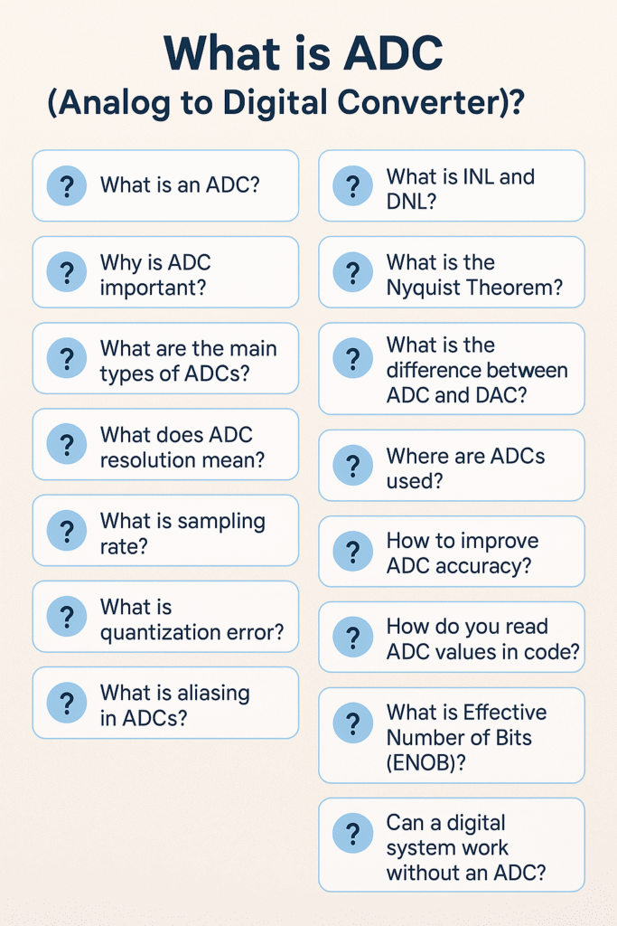
    1. What is an ADC?

    An ADC (Analog to Digital Converter) is an electronic device that converts continuous analog signals (like voltage) into discrete digital numbers that a microcontroller or computer can process.

    2. Why is ADC important?

    Digital systems (like microcontrollers) cannot understand analog signals directly. ADCs allow these systems to sense real-world signals such as temperature, sound, and light.

    3. What are the main types of ADCs?

    • Successive Approximation Register (SAR) ADC
    • Flash ADC
    • Sigma-Delta (ΔΣ) ADC
    • Dual Slope ADC
    • Pipelined ADC

    4. What does ADC resolution mean?

    ADC resolution refers to the number of bits used to represent the analog signal. For example, a 10-bit ADC divides the voltage range into 210=10242^{10} = 1024 levels.

    5. What is sampling rate?

    Sampling rate is the number of times per second the ADC samples the analog signal. It’s measured in samples per second (S/s or Hz).

    6. What is quantization error?

    Quantization error is the difference between the actual analog input and its closest digital representation. It’s an inherent limitation of ADC resolution.

    7. What is aliasing in ADCs?

    Aliasing occurs when the signal is sampled below the Nyquist rate (less than twice the highest signal frequency), causing distortion. An anti-aliasing filter is used to prevent this.

    8. What is INL and DNL?

    • INL (Integral Non-Linearity): Deviation of ADC output from the ideal line across the full range.
    • DNL (Differential Non-Linearity): Deviation in step size between adjacent digital codes.

    9. What is the Nyquist Theorem?

    It states that to accurately sample a signal, the sampling rate must be at least twice the highest frequency present in the signal.

    10. What is the difference between ADC and DAC?

    • ADC: Converts analog to digital.
    • DAC (Digital to Analog Converter): Converts digital back to analog.

    11. Where are ADCs used?

    • Microcontrollers (sensors)
    • Audio recording systems
    • Medical devices (ECG)
    • Communication systems
    • Industrial automation

    12. How to improve ADC accuracy?

    • Use a stable voltage reference
    • Reduce electrical noise
    • Use averaging in software
    • Shield analog paths from digital interference

    13. How do you read ADC values in code?

    You configure the ADC module (select channel, resolution, start conversion) and then read the digital value from a register (e.g., ADC_READ() in many platforms).

    14. What is Effective Number of Bits (ENOB)?

    ENOB indicates the actual resolution of an ADC considering all sources of noise and distortion.

    15. Can a digital system work without an ADC?

    Yes, if it only processes digital signals. But to interact with the real world (sensors, audio, etc.), an ADC is essential.

    You can also Visit other tutorials of Embedded Prep 

    Special thanks to @mr-raj for contributing to this article on Embedded Prep

  • Master Understanding of GPIO: Beginner-Friendly Tutorial (2026)

    Introduction to GPIO

    GPIO : In the world of electronics and embedded systems, GPIO is a term you will encounter very often.
    GPIO stands for General Purpose Input/Output. It refers to programmable pins on a microcontroller, microprocessor, or SoC (System on Chip) that can be controlled through software to perform simple tasks like reading a sensor value or controlling an LED.

    In this beginner-friendly tutorial, we will break down GPIOs in a very simple way, perfect for those just getting started!

    What is GPIO?

    GPIO pins are versatile electrical connections.
    They can be configured either as input or output depending on what you want to do:

    • Input Mode: The GPIO pin reads a signal, such as a button press.
    • Output Mode: The GPIO pin sends a signal, such as turning on an LED or running a motor.

    Think of GPIO pins as the communication wires between your software and hardware.

    Why is GPIO Important?

    GPIO pins allow microcontrollers and processors to interact with the physical world.
    Without GPIO, you wouldn’t be able to connect buttons, sensors, LEDs, or many other hardware components to your board.

    They are used for:

    • Reading data from sensors (temperature, humidity, motion, etc.)
    • Controlling outputs (LEDs, motors, relays)
    • Communicating with other devices (using protocols like SPI, I2C, UART)

    How Does GPIO Work?

    Basic Steps:

    1. Configure the Pin Direction
      • Set the GPIO pin as either INPUT or OUTPUT.
    2. Write or Read Data
      • If OUTPUT, send a HIGH (1) or LOW (0) voltage.
      • If INPUT, read the voltage level to determine the signal (pressed, not pressed, etc.).
    3. Use Pull-up or Pull-down Resistors
      • These resistors ensure the GPIO pin has a default voltage when nothing is connected.

    Real-World Example: Blinking an LED with GPIO

    Let’s understand GPIO with a simple example: Blinking an LED using a microcontroller like Arduino.

    Components Needed:

    • 1 x LED
    • 1 x 220-ohm resistor
    • 1 x Arduino board
    • Breadboard and wires

    Circuit Connection:

    • Connect the longer leg of the LED (anode) to GPIO pin 13 through the resistor.
    • Connect the shorter leg (cathode) to GND (Ground).

    Arduino Code Example:

    void setup() {
      pinMode(13, OUTPUT); // Set GPIO 13 as OUTPUT
    }
    
    void loop() {
      digitalWrite(13, HIGH); // Turn LED ON
      delay(1000);            // Wait for 1 second
      digitalWrite(13, LOW);  // Turn LED OFF
      delay(1000);            // Wait for 1 second
    }
    

    Explanation:

    • pinMode(13, OUTPUT) configures pin 13 as an output pin.
    • digitalWrite(13, HIGH) sends a HIGH voltage to turn on the LED.
    • digitalWrite(13, LOW) sends a LOW voltage to turn off the LED.
    • delay(1000) waits for 1000 milliseconds (1 second) between ON and OFF.

    Important GPIO Terms You Should Know

    TermMeaning
    HIGHLogical 1 or 3.3V/5V (depending on board)
    LOWLogical 0 or 0V (Ground)
    Pull-up resistorKeeps input HIGH when switch is open
    Pull-down resistorKeeps input LOW when switch is open

    Best Practices When Working with GPIOs

    • Always check the maximum voltage and current that your GPIO pin can handle.
    • Use resistors to protect your GPIO pins from damage.
    • Debounce inputs like buttons to avoid false triggering.
    • When using output GPIOs to drive high-power devices (like motors), use transistors or relays.

    GPIO Practical Example on ARM Cortex-M4 Processor (STM32)

    Introduction

    When working with ARM Cortex-M4 microcontrollers (like STM32F4 series), controlling GPIO pins is one of the first and most important tasks you’ll learn.

    In this tutorial, we’ll show you how to configure a GPIO pin to blink an LED using STM32 microcontroller, and understand what’s happening step-by-step!

    Let’s dive right in. 🚀

    Prerequisites

    Before we start, you should have:

    • An STM32F4 (or similar Cortex-M4 board)
    • STM32CubeIDE installed (free official IDE from STMicroelectronics)
    • A basic setup (board, USB cable)

    GPIO Basics on ARM Cortex-M4

    On STM32, each pin is part of a GPIO port like GPIOA, GPIOB, GPIOC, etc.

    Each GPIO pin needs:

    • Clock Enable (for the GPIO port)
    • Pin Mode Configuration (Input, Output, Alternate Function, Analog)
    • Output Type (Push-Pull or Open-Drain)
    • Pull-up/Pull-down (None, Pull-up, Pull-down)
    • Speed (Low, Medium, High)

    Step-by-Step: Blinking an LED on STM32 (Cortex-M4)

    1. Hardware Setup

    • Use the on-board LED (usually connected to Pin PA5 on Nucleo-F401RE, or check your board’s datasheet).
    • If no onboard LED, connect an LED through a resistor to PA5 and GND.

    2. Software Setup (STM32CubeIDE)

    Create a New STM32 Project:

    1. Open STM32CubeIDE.
    2. Click File > New > STM32 Project.
    3. Select your MCU (example: STM32F401RE).
    4. Name your project (GPIO_Blink).

    Configure GPIO:

    In the Pinout & Configuration view:

    • Click on pin PA5 (or your chosen pin).
    • Set it as GPIO_Output.

    CubeIDE automatically configures the GPIO clock and settings!

    3. Write the Code

    Go to Src/main.c and edit the code:

    #include "main.h"
    
    int main(void)
    {
      HAL_Init(); // Initialize Hardware Abstraction Layer
      
      __HAL_RCC_GPIOA_CLK_ENABLE(); // Enable clock for GPIOA
    
      GPIO_InitTypeDef GPIO_InitStruct = {0};
    
      // Configure PA5 as Output
      GPIO_InitStruct.Pin = GPIO_PIN_5;
      GPIO_InitStruct.Mode = GPIO_MODE_OUTPUT_PP; // Push-Pull Output
      GPIO_InitStruct.Pull = GPIO_NOPULL;
      GPIO_InitStruct.Speed = GPIO_SPEED_FREQ_LOW;
      HAL_GPIO_Init(GPIOA, &GPIO_InitStruct);
    
      while (1)
      {
        HAL_GPIO_TogglePin(GPIOA, GPIO_PIN_5); // Toggle LED
        HAL_Delay(500);                        // Delay 500 ms
      }
    }
    

    4. Build and Flash the Code

    • Click the hammer icon (build project).
    • Connect your board.
    • Click the green play button (flash and run).

    You should see the LED blinking every 500ms!

    What’s Happening Behind the Scenes?

    StepDescription
    HAL_Init()Initializes the HAL Library.
    __HAL_RCC_GPIOA_CLK_ENABLE()Enables the clock for GPIOA peripheral.
    HAL_GPIO_Init()Sets pin PA5 as output, no pull-up/down, low speed.
    HAL_GPIO_TogglePin()Changes pin state (HIGH to LOW or LOW to HIGH).
    HAL_Delay()Creates a software delay to control blink rate.

    Tips for GPIO on ARM Cortex-M4

    • Always enable the clock for the GPIO port before configuring.
    • Use HAL library for easier and safer coding (good for beginners).
    • For high-speed GPIO, set GPIO Speed to GPIO_SPEED_FREQ_HIGH.
    • Read the Reference Manual of your microcontroller to understand more detailed control.

    Imagine it like this:

    A GPIO pin is like a small door.

    • When you listen at the door → It’s an input.
    • When you shout through the door → It’s an output.

    And you (the programmer) decide whether to listen or shout through the door!

    How GPIO Works Internally (Step-by-Step)

    1. GPIO Pin is Connected to Internal Hardware

    Every GPIO pin is connected to a small electrical circuit inside the microcontroller.
    This circuit can behave differently based on how you configure it.

    At its heart, the pin connects to:

    • Logic gates
    • Pull-up/pull-down resistors
    • Drive transistors
    • MUX (Multiplexer for selecting function)

    2. Configure the Pin as Input or Output

    When you write software for your MCU, the first thing you do is configure the pin:

    • Input mode: The pin will listen to outside voltage (HIGH or LOW).
    • Output mode: The pin will send a voltage signal (HIGH or LOW) outside.

    💬 In most microcontrollers, you configure this using special control registers (small memory locations inside the chip).

    Example (STM32):

    GPIOA->MODER |= (1 << (2 * 5));  // Set PA5 as output
    

    This means you’re telling the chip: “Hey, PA5, work as output!

    3. How Input Mode Works

    When the pin is in input mode:

    • It waits and senses if the voltage on the pin is High (1) or Low (0).
    • High means ~3.3V (depends on MCU).
    • Low means ~0V.

    If the signal is unstable, internal pull-up or pull-down resistors can be activated to stabilize it.

    4. How Output Mode Works

    When the pin is in output mode:

    • The software can write 1 or 0 to the pin.
    • Writing 1: The internal circuit connects the pin to 3.3V (HIGH).
    • Writing 0: The internal circuit connects the pin to GND (LOW).

    Example (STM32 HAL):

    HAL_GPIO_WritePin(GPIOA, GPIO_PIN_5, GPIO_PIN_SET); // Set PA5 High
    HAL_GPIO_WritePin(GPIOA, GPIO_PIN_5, GPIO_PIN_RESET); // Set PA5 Low
    

    Thus, the pin can turn ON an LED, activate a motor, or send data to another device.

    5. Special Features Inside GPIO

    GPIOs are not just dumb wires. They have smart features:

    FeatureMeaning
    Pull-up / Pull-downStabilize input when nothing connected
    Open-DrainPin can pull LOW but not drive HIGH (external pull-up needed)
    Speed ControlControl how fast pin changes (important for EMI)
    Alternate FunctionsGPIO can become UART, SPI, I2C pins when needed
    Interrupt CapabilityGPIO can detect changes and alert CPU instantly

    GPIO Life Cycle in Software

    Typical steps in a C program:

    1. Enable the GPIO port clock (power the module).
    2. Configure the pin mode (input/output/alternate).
    3. Set pull-up or pull-down resistors if needed.
    4. Set speed (for output pins).
    5. Read or Write data.

    This process never changes — whether you’re working on STM32, NXP, or TI boards.

    Real-Life Practical Example (ARM Cortex-M4)

    Example Task: Blink an LED using PA5 pin

    Software Steps:

    // 1. Enable GPIOA Clock
    RCC->AHB1ENR |= (1 << 0); // Enable clock to GPIOA
    
    // 2. Set PA5 as output
    GPIOA->MODER &= ~(3 << (2 * 5)); // Clear Mode Bits
    GPIOA->MODER |= (1 << (2 * 5));  // Set Output Mode
    
    // 3. Toggle PA5 forever
    while(1) {
        GPIOA->ODR ^= (1 << 5); // Toggle PA5
        for (volatile int i = 0; i < 100000; i++); // Small delay
    }
    

    Result:
    The LED connected to PA5 will blink continuously.

    Important Concepts to Remember

    ConceptSummary
    Input ModeReads voltage from external world
    Output ModeSends voltage to external world
    FloatingInput pin without pull-up/down can behave randomly
    Pull-up/Pull-downAvoid undefined signals on inputs
    Open-Drain OutputSafer for multi-device communication
    Alternate FunctionsTurn GPIO into UART, SPI, I2C, PWM, etc.
    DebounceClean noisy signals from mechanical buttons

    GPIO Interview Questions for Embedded Systems

    Basic Level

    1. What is GPIO? Explain its role in microcontrollers.
    2. What is the difference between GPIO input and GPIO output?
    3. What are pull-up and pull-down resistors? Why are they important in GPIO input mode?
    4. How do you configure a GPIO pin as an output in ARM Cortex-M4?
    5. What happens if you leave a GPIO input pin floating?
    6. What is the difference between push-pull and open-drain output configurations?
    7. Explain the concept of debouncing. Why is it needed for GPIO inputs?

    Intermediate Level

    1. Describe the steps needed to configure a GPIO pin manually (without using a HAL library).
    2. What registers are involved in GPIO configuration on ARM Cortex-M4 (STM32)?
    3. How would you implement GPIO interrupts for a button press?
    4. Explain the importance of enabling the peripheral clock before accessing GPIO registers.
    5. What is alternate function mode in GPIOs? Give examples where it’s used.
    6. How would you drive an LED matrix using GPIOs?
    7. What are the power considerations when using GPIOs, especially in battery-operated devices?
    8. What is GPIO drive strength? Why does it matter in certain designs?

    Advanced Level

    1. Explain how you would design a low-power GPIO input system.
    2. Describe a scenario where open-drain GPIO configuration is preferred over push-pull.
    3. How do you configure GPIO wake-up from sleep or standby mode in ARM Cortex-M4?
    4. How would you handle a situation where multiple peripherals share the same GPIO pins?
    5. What are the risks of GPIO glitches during boot or reset, and how can you minimize them?
    6. How do GPIO multiplexers work internally in microcontrollers?
    7. How would you optimize GPIO control for high-speed applications (e.g., toggling pins in MHz range)?

    Practical / Coding Level

    1. Write a C code snippet to configure PA0 as input with pull-up resistor on STM32.
    2. Write a code to toggle a GPIO pin at a 1-second interval without using HAL libraries.
    3. How would you structure GPIO initialization code for easy scalability in large embedded projects?

    Bonus Questions (for Deeper Insight)

    • Have you ever used GPIO pins for bit-banging protocols like I2C or SPI? Explain how.
    • What are the key differences in GPIO handling between STM32, NXP, and TI microcontrollers?
    • How would you simulate a GPIO toggle using a timer interrupt?

    GPIO FAQs (Frequently Asked Questions)

    1. What is GPIO in a microcontroller?

    Answer:
    GPIO stands for General Purpose Input/Output. It allows microcontrollers to read external signals (input) or control external devices (output) like LEDs, buttons, sensors, motors, etc.

    2. What is the difference between GPIO input and GPIO output?

    Answer:

    • GPIO Input: Reads external signals (like button presses or sensor outputs).
    • GPIO Output: Sends signals to control external devices (like LEDs, buzzers, relays).

    3. What are pull-up and pull-down resistors in GPIO?

    Answer:
    Pull-up and pull-down resistors prevent GPIO input pins from floating (i.e., being in an undefined state) by tying them to a known voltage:

    • Pull-up: Connects the pin weakly to Vcc (logic high).
    • Pull-down: Connects the pin weakly to GND (logic low).

    4. Why do we enable the GPIO clock before using GPIO?

    Answer:
    Microcontrollers use clock gating to save power.
    Without enabling the GPIO clock, the GPIO registers are inaccessible, and the pin cannot function properly.

    5. What is the purpose of GPIO alternate function mode?

    Answer:
    Alternate function mode allows a GPIO pin to be repurposed for other hardware functions like:

    • UART (Serial communication)
    • SPI (Serial Peripheral Interface)
    • I2C (Inter-Integrated Circuit)
    • PWM (Pulse Width Modulation)

    6. What is push-pull vs open-drain GPIO configuration?

    Answer:

    • Push-Pull: The pin can actively drive both high and low voltage levels.
    • Open-Drain: The pin can only pull the line low or stay floating (external pull-up required).

    Tip: Open-drain is commonly used in I2C and shared-bus designs.

    7. What happens if a GPIO input pin is left floating?

    Answer:
    If left floating, the GPIO input can randomly read HIGH or LOW, causing unpredictable behavior due to electrical noise.
    Solution: Always configure input pins with a pull-up or pull-down resistor.

    8. How to configure a GPIO pin in STM32?

    Answer:
    Steps to configure:

    1. Enable the GPIO port clock.
    2. Set the pin mode (Input/Output/Alternate/Analog).
    3. Configure output type (Push-Pull/Open-Drain).
    4. Set pull-up/pull-down resistors.
    5. Define pin speed (Low/Medium/High).
    6. Write or read data to/from the pin.

    9. How to toggle a GPIO pin in C?

    Answer:
    Example (STM32 HAL):

    HAL_GPIO_TogglePin(GPIOA, GPIO_PIN_5);
    

    This function toggles the state of the specified GPIO pin.

    10. What is debouncing and why is it needed for GPIO inputs?

    Answer:
    Debouncing is the process of removing noisy, fast-changing signals generated by mechanical switches when pressed or released.
    Without debouncing, a single button press might be registered as multiple presses.

    Solutions:

    • Software debounce (adding small delay)
    • Hardware debounce (using capacitors or circuits)

    11. Can GPIOs be used for interrupts?

    Answer:
    Yes!
    GPIOs can be configured to generate interrupts on events like:

    • Rising edge (LOW to HIGH)
    • Falling edge (HIGH to LOW)
    • Both edges

    This is useful for buttons, sensors, and real-time events.

    12. How fast can a GPIO toggle?

    Answer:
    It depends on:

    • Microcontroller clock speed
    • GPIO speed settings (Low/Medium/High/Fast)
    • Code execution time

    With direct register access (bare-metal), GPIOs can toggle at several megahertz (MHz) frequencies.

    13. How can I reduce GPIO power consumption?

    Answer:
    To minimize GPIO power use:

    • Set unused GPIOs to analog mode.
    • Avoid floating inputs.
    • Use pull-downs or pull-ups appropriately.
    • Reduce output toggle frequency if not needed.

    14. How to protect GPIO pins from damage?

    Answer:
    Protection methods:

    • Use series resistors.
    • Use TVS (Transient Voltage Suppression) diodes.
    • Never exceed the maximum voltage/current ratings.
    • Add current-limiting resistors for outputs like LEDs.

    15. What is GPIO multiplexing?

    Answer:
    GPIO multiplexing allows one physical pin to perform multiple functions based on configuration (e.g., GPIO, UART TX, SPI MISO, etc.).
    The correct function is selected by setting MUX bits in the configuration registers.

    Special thanks to @mr-raj for contributing to this article on Embedded Prep

  • Master Polling in Embedded Systems (2026)

    Polling in Embedded Systems : In the world of embedded systems, efficient communication and control are the backbone of creating robust, reliable devices. One of the most common techniques used in embedded systems is polling. Whether you’re building a microcontroller-based project, working with real-time operating systems (RTOS), or diving into low-level programming, understanding how polling works is essential.

    This article will walk you through the concept of polling in embedded systems, making it easy for beginners to grasp. Plus, we’ll discuss how it compares to other methods like interrupt-driven systems. By the end of this article, you’ll have a clear understanding of polling, its applications, and how to implement it effectively in embedded projects.

    What are Embedded Systems?

    An embedded system is a specialized computer designed to perform specific tasks within a larger system. Unlike general-purpose computers (like your laptop or desktop), embedded systems are designed to do a single job efficiently. Examples include smart thermostats, automobiles, washing machines, and smartwatches.

    Key characteristics of embedded systems:

    • Dedicated Functionality: They are designed to perform a specific task or a set of related tasks.
    • Real-time Operation: Many embedded systems need to meet real-time constraints, which means they must respond to events within a specified time.
    • Low Power Consumption: These systems are often battery-powered or energy-efficient.
    • Hardware-Software Integration: Embedded systems typically combine both hardware (e.g., microcontrollers, sensors) and software (e.g., embedded C code, firmware).

    Polling in Embedded Systems: An Overview

    Polling is a method used in embedded systems to continuously check or “poll” a specific resource, sensor, or status register at regular intervals. It involves checking the status of a peripheral or input/output (I/O) device to determine if any action is needed.

    How Polling Works:

    1. Check the Status: The system regularly checks whether a certain condition or event has occurred (e.g., button press, sensor data available).
    2. Wait for Action: If the condition is met, the system performs the required action (e.g., turning on a light, sending data).
    3. Repeat the Process: After performing the action, the system continues to check the status in a continuous loop.

    Example of Polling:

    Imagine a simple embedded system connected to a temperature sensor. The system might check the sensor’s value every second to determine if the temperature has crossed a threshold. If the threshold is exceeded, the system might trigger a fan or an alarm.

    Polling vs. Interrupts: What’s the Difference?

    While polling is a simple and easy-to-understand approach, it’s not always the most efficient. The main alternative to polling is the interrupt-driven approach.

    Polling:

    • Process: The system checks for events at regular intervals.
    • Efficiency: Polling can be inefficient, especially when there are no events to handle.
    • CPU Load: It consumes CPU cycles even if no action is needed, which may lead to unnecessary power consumption.
    • Simplicity: Polling is easy to implement, making it a popular choice for simple applications.

    Interrupts:

    • Process: The system waits for an external event, and when the event occurs, it triggers an interrupt to immediately respond to the event.
    • Efficiency: Interrupts are more efficient since the CPU doesn’t have to constantly check for events.
    • CPU Load: The CPU remains idle until an interrupt occurs, saving energy.
    • Complexity: Interrupt-driven systems are more complex to implement and require careful management.

    Which One to Use?

    For simple applications with limited resources (e.g., small microcontrollers), polling is a straightforward and practical choice. However, for more complex systems that need to handle multiple events simultaneously, interrupts provide better performance and efficiency.

    Advantages and Disadvantages of Polling

    Advantages of Polling:

    1. Simplicity: Polling is easy to implement and understand, making it ideal for beginners.
    2. Predictability: Polling allows you to have complete control over the timing of checks and actions.
    3. Low Overhead: In small systems with minimal processing power, polling can be a low-overhead approach.

    Disadvantages of Polling:

    1. Inefficiency: If the system is checking for events continuously, but nothing happens, it’s wasting processing power.
    2. Latency: In some cases, polling may introduce delays in responding to events, especially if the polling interval is too long.
    3. CPU Intensive: Polling can put unnecessary strain on the CPU, especially when many resources are being monitored.

    Applications of Polling in Embedded Systems

    Polling is commonly used in many embedded system applications. Here are a few examples:

    1. Button Press Detection: Polling can be used to detect when a button is pressed. The microcontroller continuously checks the state of the button, and once it detects a press, it can perform an action (e.g., turning on a light).
    2. Sensor Monitoring: In systems where sensors continuously measure parameters (e.g., temperature, humidity, or pressure), polling can be used to check sensor data at regular intervals.
    3. Communication Protocols: Polling is often used in communication protocols like UART or SPI, where data is checked periodically to determine if new information is available.
    4. LED Status Checking: Simple systems that involve controlling LEDs based on specific conditions can use polling to monitor input values and determine if the LED needs to be turned on or off.

    How to Implement Polling in Embedded Systems

    Implementing polling in an embedded system can be as simple as using a while loop or timer interrupt. Here’s a basic example of polling a button press on a microcontroller using C:

    #define BUTTON_PIN 3
    
    void setup() {
      pinMode(BUTTON_PIN, INPUT);
    }
    
    void loop() {
      // Poll the button state every cycle
      int buttonState = digitalRead(BUTTON_PIN);
      
      if (buttonState == HIGH) {
        // Button is pressed, perform action
        digitalWrite(LED_PIN, HIGH);
      } else {
        // Button is not pressed, turn off LED
        digitalWrite(LED_PIN, LOW);
      }
      
      delay(100); // Delay to avoid busy-waiting
    }
    

    In this simple code, the system continuously checks if a button is pressed and controls an LED based on the button’s state.

    Implement polling for a button press on the STM32

    Here’s how you can implement polling for a button press on the STM32F407VG microcontroller, specifically for a simple embedded system that checks the state of a button and toggles an LED when the button is pressed.

    Prerequisites:

    • STM32CubeMX for generating initialization code.
    • STM32 HAL library for easy peripheral management.
    • A button connected to a GPIO pin (e.g., GPIO pin PA0).
    • An LED connected to another GPIO pin (e.g., GPIO pin PC13).

    Step-by-Step Implementation

    Step 1: Setting up the STM32CubeMX Project

    1. Open STM32CubeMX and create a new project for the STM32F407VG.
    2. Configure the Button Pin:
      • Set PA0 (or any other GPIO pin) as an input pin.
    3. Configure the LED Pin:
      • Set PC13 (or any other GPIO pin) as an output pin.
    4. Enable the Clock for GPIO: CubeMX will automatically enable the necessary clocks.
    5. Generate the initialization code for your project by clicking on Project -> Generate Code.

    Step 2: Writing the Code

    Once the code has been generated, open it in STM32CubeIDE and write the logic for polling the button state.

    1. Open the main.c file to implement the logic.
    2. In the main.c, include the necessary headers and initialize the GPIO pins.
    #include "main.h"
    
    int main(void)
    {
      // HAL Initialization
      HAL_Init();
    
      // Initialize the System Clock
      SystemClock_Config();
    
      // Initialize the GPIO for button (PA0) and LED (PC13)
      MX_GPIO_Init();
    
      while (1)
      {
        // Poll the button state
        if (HAL_GPIO_ReadPin(GPIOA, GPIO_PIN_0) == GPIO_PIN_SET)  // If button is pressed
        {
          // Turn ON the LED
          HAL_GPIO_WritePin(GPIOC, GPIO_PIN_13, GPIO_PIN_SET);
        }
        else
        {
          // Turn OFF the LED
          HAL_GPIO_WritePin(GPIOC, GPIO_PIN_13, GPIO_PIN_RESET);
        }
    
        // Small delay to avoid bouncing issues
        HAL_Delay(50);  // 50ms delay
      }
    }
    

    Step 3: Configure the GPIO Pins in gpio.c

    The GPIO configuration will be handled by the generated MX_GPIO_Init() function, but ensure that the input and output pins are configured as follows:

    void MX_GPIO_Init(void)
    {
      GPIO_InitTypeDef GPIO_InitStruct = {0};
    
      // Enable GPIOA and GPIOC clocks
      __HAL_RCC_GPIOA_CLK_ENABLE();
      __HAL_RCC_GPIOC_CLK_ENABLE();
    
      // Configure GPIO pin for the button (PA0) as input
      GPIO_InitStruct.Pin = GPIO_PIN_0;
      GPIO_InitStruct.Mode = GPIO_MODE_INPUT;
      GPIO_InitStruct.Pull = GPIO_NOPULL;
      HAL_GPIO_Init(GPIOA, &GPIO_InitStruct);
    
      // Configure GPIO pin for the LED (PC13) as output
      GPIO_InitStruct.Pin = GPIO_PIN_13;
      GPIO_InitStruct.Mode = GPIO_MODE_OUTPUT_PP;
      GPIO_InitStruct.Pull = GPIO_NOPULL;
      GPIO_InitStruct.Speed = GPIO_SPEED_FREQ_LOW;
      HAL_GPIO_Init(GPIOC, &GPIO_InitStruct);
    }
    

    Step 4: System Clock Configuration

    Ensure the SystemClock_Config() function is correctly implemented to set the system clock. This is usually automatically configured by STM32CubeMX.

    void SystemClock_Config(void)
    {
      // System Clock Configuration code generated by STM32CubeMX
    }
    

    Step 5: Compiling and Flashing

    1. Compile the project by clicking on the “Build” button in STM32CubeIDE.
    2. Flash the code onto the STM32F407VG using a programmer like ST-Link or J-Link.

    Step 6: Testing

    1. When you press the button connected to PA0, the LED on PC13 will turn ON.
    2. When you release the button, the LED will turn OFF.

    Notes:

    • Button Debouncing: In real-world applications, button presses can cause multiple transitions due to contact bounce. To handle this, you can implement software debouncing by introducing a small delay after detecting a button press. For example: if (HAL_GPIO_ReadPin(GPIOA, GPIO_PIN_0) == GPIO_PIN_SET) // If button is pressed { HAL_Delay(200); // Wait for 200ms for debounce if (HAL_GPIO_ReadPin(GPIOA, GPIO_PIN_0) == GPIO_PIN_SET) // Confirm button press { HAL_GPIO_WritePin(GPIOC, GPIO_PIN_13, GPIO_PIN_SET); // Turn ON LED } }

    Conclusion

    Polling is a fundamental technique used in embedded systems for monitoring peripherals and sensors. While it may not be as efficient as interrupts, polling remains a great choice for simple applications where ease of implementation and control are key priorities.

    Understanding polling helps you build a foundation in embedded system development and prepares you for more advanced concepts, such as interrupt handling and real-time operating systems.

    By leveraging polling effectively, you can build efficient embedded systems that perform their tasks reliably. Now that you’ve got a basic understanding of polling, experiment with it in your projects and see how it can simplify your embedded designs!

    Polling Interview Questions in Embedded Systems

    1. Basic Concept of Polling

    • What is polling in embedded systems?
    • How does polling differ from interrupt-driven I/O in embedded systems?
    • What are the advantages of using polling over interrupts?
    • What are the disadvantages of using polling over interrupts?

    2. Polling Mechanism

    • How does the polling mechanism work in microcontrollers?
    • What is the role of a loop in a polling system?
    • What happens if polling does not check the condition in time?
    • How do you implement polling in an embedded system using a microcontroller?

    3. Performance and Efficiency

    • How does polling affect the performance of an embedded system?
    • What are the power consumption implications of using polling?
    • How can polling impact the responsiveness of real-time systems?
    • When is polling an appropriate method for handling input/output operations?

    4. Polling vs Interrupts

    • What are the main differences between polling and interrupts?
    • When would you choose polling over interrupts in an embedded system?
    • Can polling be used for real-time applications? Why or why not?
    • What are the trade-offs between using polling and interrupts for managing hardware resources?

    5. Polling in Practice

    • How would you use polling to check the status of a button press in an embedded system?
    • How do you implement polling for an analog-to-digital conversion (ADC) in an embedded system?
    • How does polling work in a sensor-based system (e.g., temperature or pressure sensors)?
    • How can you poll multiple devices in an embedded system without affecting performance?

    6. Timing and Delays in Polling

    • How do you manage timing and delays in polling-based systems?
    • What is the role of software timers in polling systems?
    • How can you avoid excessive CPU usage in polling systems with tight timing requirements?

    7. Polling and System Design

    • How does polling impact the overall system design in an embedded system?
    • Can polling be used in safety-critical embedded systems? Why or why not?
    • How can you optimize a polling-based embedded system for better performance?
    • What are some examples of systems that are ideal candidates for polling-based designs?

    8. Polling and Real-Time Operating Systems (RTOS)

    • How does polling interact with an RTOS in embedded systems?
    • What are the challenges of implementing polling in a system with an RTOS?
    • How does an RTOS handle polling tasks in comparison to interrupt-based tasks?

    9. Advanced Polling Techniques

    • How do you implement efficient polling for high-frequency data in embedded systems?
    • What strategies can be used to handle multiple input devices through polling without bottlenecking?
    • How can you combine polling with other techniques (e.g., interrupt handling) to improve performance?

    10. Polling in Communication Protocols

    • How does polling work in communication protocols like SPI, I2C, or UART?
    • How do you handle polling when multiple devices are involved in a communication protocol?
    • How do polling and baud rates relate in serial communication?

    Here’s an FAQ for “Introduction to Embedded Systems: Polling Explained for Beginners”:

    FAQ: Polling in Embedded Systems

    1. What is polling in embedded systems?

    • Answer: Polling is a technique in embedded systems where the microcontroller continuously checks the status of an input or a device at regular intervals. The system “polls” the device to see if any action is required, such as reading a sensor or checking for an interrupt.

    2. Why is polling used in embedded systems?

    • Answer: Polling is used in embedded systems for simple tasks where real-time performance is not critical. It provides a way to monitor inputs or devices without complex interrupt-driven mechanisms. It’s easy to implement and doesn’t require handling interrupts, which can complicate system design.

    3. What are the advantages of polling?

    • Answer:
      • Simplicity: Polling is straightforward to implement and doesn’t require additional configuration like interrupts.
      • Control: The system has control over when and how often it checks inputs, which can be useful in some applications.
      • No need for interrupts: Polling eliminates the need for interrupt handling, which can be complex to manage in some systems.

    4. What are the disadvantages of polling?

    • Answer:
      • Inefficiency: Polling constantly uses the CPU, which can lead to wasted processing power, especially if the event being polled for happens infrequently.
      • Latency: If the polling interval is too large, the system may take longer to detect and respond to important events.
      • No real-time response: Since the system is busy checking the device regularly, it may not respond quickly to other tasks or inputs that require immediate attention.

    5. How does polling differ from interrupt handling?

    • Answer: Polling involves checking a device’s status at regular intervals, while interrupt handling allows the system to respond to events immediately when they occur. With interrupts, the system can react to a specific event as soon as it happens without constantly checking the device.

    6. When should polling be used?

    • Answer: Polling is best suited for simple tasks where the event rate is low, and real-time performance is not a strict requirement. For instance, it can be used to read sensors periodically or check switches in low-complexity systems.

    7. What is the typical polling frequency in embedded systems?

    • Answer: The polling frequency depends on the application. It can range from milliseconds to seconds, based on the nature of the task. In some cases, polling might happen every few milliseconds, while in others, it could be slower, depending on how often the device or sensor needs to be checked.

    8. Can polling be used in real-time systems?

    • Answer: Polling can be used in real-time systems, but it is not ideal for systems requiring quick responses to external events. For real-time systems, interrupts or other real-time scheduling techniques are preferred to achieve low latency.

    9. What is the role of polling in low-power embedded systems?

    • Answer: In low-power systems, polling can be designed to minimize power consumption by having the system enter low-power states between polling intervals. However, if not properly managed, polling can increase power usage, especially in devices that need to be continuously active.

    10. What are some examples of polling in embedded systems?

    • Answer:
      • Reading temperature sensors in a weather station.
      • Checking for a button press in a microcontroller-based device.
      • Monitoring a status register in a peripheral device, such as an ADC (Analog-to-Digital Converter).

    11. Can polling be combined with interrupts?

    • Answer: Yes, polling and interrupts can be combined. For example, polling can be used for less time-critical tasks, while interrupts handle more urgent events. This hybrid approach allows a system to manage different types of tasks effectively.

    12. What is a polling loop?

    • Answer: A polling loop is a continuous loop in the code where the system repeatedly checks the status of a device or sensor. The loop keeps running until a specific condition is met, such as a button being pressed or a sensor reading exceeding a threshold.

    You can also Visit other tutorials of Embedded Prep 

    Special thanks to @mr-raj for contributing to this article on Embedded Prep

  • Interrupts in Embedded Systems : A Complete Beginner’s Guide 2026

    Introduction

    Interrupts in Embedded Systems : An interrupt is a way for hardware or software to get the processor’s attention when something important happens. It’s like someone tapping you on the shoulder while you are busy working, saying, “Hey, look at this right now!”

    When an interrupt happens, the processor doesn’t stop immediately. It first finishes the instruction it is currently working on. After that, it quickly moves to a special piece of code called the Interrupt Service Routine (ISR) or Interrupt Handler.

    The ISR is like a small program that tells the processor what to do when a specific interrupt occurs. For example, if you press a button connected to your device, the processor will run the ISR to check which button was pressed and what action should be taken.

    In the world of embedded systems, interrupts are powerful tools that help a device respond quickly to important events. Instead of constantly checking (polling) whether something has happened, interrupts alert the processor immediately, saving time and power.

    What is an Interrupt?

    An interrupt is a signal that pauses the normal flow of a program and forces the CPU to run a special piece of code called an Interrupt Service Routine (ISR).

    After the ISR finishes, the CPU resumes its previous work as if nothing happened.

    In simple words:
    An interrupt is like someone tapping your shoulder to get your attention while you are busy working.

    Why are Interrupts Important?

    Interrupts offer several benefits in embedded systems:

    • Real-time Response: Immediate reaction to critical events like button presses, sensor readings, or incoming data.
    • Efficiency: No need to waste CPU time constantly checking for events.
    • Power Saving: Processor can stay in low-power modes and wake up only when needed.
    • Multitasking: Perform multiple tasks effectively without missing important signals.

    How Interrupts Work: Step-by-Step

    Here’s a simple flow of how interrupts work:

    1. Normal Execution: CPU is busy running the main program.
    2. Interrupt Event: An external or internal event occurs (like a button press).
    3. Interrupt Request: The event triggers an interrupt request to the CPU.
    4. Interrupt Handling:
      • CPU pauses the main program.
      • CPU saves the current program state (so it can return later).
      • CPU jumps to the Interrupt Service Routine (ISR).
    5. ISR Execution: Special code in ISR runs to handle the event.
    6. Return to Main Program: CPU restores the saved state and continues where it left off.

    Real-World Example of Interrupt

    Imagine a smart doorbell:

    • Normally, the microcontroller is managing Wi-Fi or saving battery in sleep mode.
    • When a visitor presses the doorbell button, it sends an interrupt.
    • The microcontroller wakes up immediately and rings the chime or sends a notification.

    Without interrupts, the microcontroller would have to keep checking the button all the time, wasting energy.

    Key Components of an Interrupt System

    • Interrupt Request (IRQ): The signal that notifies the CPU about an event.
    • Interrupt Vector Table (IVT): A table that holds the addresses of all ISRs.
    • Interrupt Service Routine (ISR): A short program that handles the interrupt.
    • Interrupt Controller: Manages multiple interrupts and prioritizes them if needed.

    Simple Code Example (Pseudocode)

    #include <some_microcontroller_library.h>
    
    // Define Interrupt Service Routine
    void button_press_ISR(void) {
        // Code to handle button press
        turnOnLED();
    }
    
    int main() {
        setupButtonInterrupt(button_press_ISR); // Link ISR to button press
        while (1) {
            // Main program continues
            doOtherTasks();
        }
    }
    

    Explanation:

    • setupButtonInterrupt() configures the button to generate an interrupt.
    • When the button is pressed, button_press_ISR() runs.
    • The main program (doOtherTasks()) keeps working without constantly checking the button.

    Best Practices When Using Interrupts

    • Keep ISR Short: The interrupt service routine should be as fast as possible.
    • Avoid Heavy Operations: No complex calculations or long delays inside the ISR.
    • Protect Shared Data: Use techniques like disabling interrupts or using volatile variables when accessing shared data.
    • Set Priorities Wisely: If multiple interrupts can occur, assign proper priorities.

    Types of Interrupts

    Interrupts are mainly divided into two big categories:

    • Hardware Interrupts
    • Software Interrupts

    And under these, there are some more types based on behavior.

    Let’s dive into each of them :

    1. Hardware Interrupts

    Definition:
    Hardware interrupts are triggered by external hardware devices like a keyboard, mouse, sensor, timer, or network card.

    Example:

    • Pressing a key on the keyboard
    • Clicking a mouse
    • Receiving data from a sensor

    When these hardware components want CPU attention, they send a signal to the CPU — “Hey, I need you now!”

    Types inside hardware interrupts:

    a) Maskable Interrupt

    • Meaning:
      These are interrupts that can be ignored (masked) by the CPU if needed.
    • Example:
      • You have a low-priority temperature sensor reading.
        CPU may postpone or disable it temporarily if a higher-priority task is running.
    • Real use:
      Useful for less urgent tasks.

    b) Non-Maskable Interrupt (NMI)

    • Meaning:
      These interrupts cannot be ignored by the CPU. They are critical.
    • Example:
      • Hardware failure like memory errors
      • Power failure warning
    • Real use:
      To handle very serious issues that must be fixed immediately to prevent damage.

    2. Software Interrupts

    Definition:
    Software interrupts are triggered by programs or instructions inside the CPU — not by external hardware.

    Example:

    • A program might intentionally request a service from the operating system, like asking to print a document 🖨️.

    How it works:
    The software uses a special instruction (often called INT) to generate an interrupt.

    Real-world Example:

    • A C program calling an operating system function like printf() indirectly uses a software interrupt to talk to the printer or screen.

    Special Classifications

    Apart from the basic two types, interrupts are often further classified based on how they are handled:

    3. Synchronous Interrupts

    • Meaning:
      Happen at predictable times, usually caused by the instruction flow of the program.
    • Example:
      • Division by zero error (mathematical mistake)
      • Invalid memory access (segmentation fault)
    • Real use:
      Catching software bugs or errors.

    4. Asynchronous Interrupts

    • Meaning:
      Happen at unpredictable times, triggered by external hardware.
    • Example:
      • User pressing a keyboard key at any moment.
      • Receiving network data.
    • Real use:
      Handling random real-world events.

    5. Vectored Interrupts

    • Meaning:
      CPU knows exactly where the Interrupt Service Routine (ISR) is located — because the address is predefined.
    • Example:
      • In ARM Cortex-M processors, vector tables store all ISR addresses.
    • Real use:
      Faster because CPU jumps directly to the correct code.

    6. Non-Vectored Interrupts

    • Meaning:
      CPU does not know directly where to go — it must find the ISR address first.
    • Example:
      • Older systems using interrupt controllers.
    • Real use:
      Slower but more flexible for dynamic interrupt management.

    Quick Summary Table

    Type of InterruptTriggered ByCan Be Masked?Predictability
    Hardware InterruptExternal deviceMaskable/Non-MaskableAsynchronous
    Software InterruptSoftware programGenerally MaskableSynchronous
    Synchronous InterruptProgram executionDependsPredictable
    Asynchronous InterruptExternal eventDependsUnpredictable
    Vectored InterruptPredefined addressFast access
    Non-Vectored InterruptDynamic addressSlower

    Final Picture

    Think of interrupts like urgent notifications in your phone:

    • 🛎️ Hardware interrupts = Phone call from someone (external event)
    • 🛎️ Software interrupts = Reminder set by yourself (internal event)
    • 🔕 Maskable = You can put it on silent
    • 🔔 Non-Maskable = Emergency call — can’t ignore
    • 📍 Vectored = Direct link to caller
    • 🔍 Non-Vectored = You have to search who’s calling first

    What is an Interrupt Service Routine (ISR)?

    Imagine you are watching your favorite TV show and suddenly your phone rings.
    You pause the show, answer the call, finish talking, and then return to watching the show.

    This is exactly what an interrupt is in a microcontroller!

    • The TV show = Main program running normally
    • Phone call = Interrupt (something urgent needing immediate attention)
    • Answering the call = Executing the Interrupt Service Routine (ISR)
    • Returning to TV = Going back to the main program after handling the interrupt

    In technical words:
    An interrupt is a signal that temporarily stops the main program and forces the microcontroller to do something else immediately.

    When an interrupt happens, the microcontroller needs to know:

    • What to do?
    • Which code to run?

    The special piece of code that runs when an interrupt occurs is called the Interrupt Service Routine (ISR).

    ➡️ In short:
    ISR = A function that is automatically called when an interrupt happens.

    How Does the Microcontroller Know Which ISR to Run?

    Every interrupt has a fixed place in memory where the microcontroller looks to find the address of the ISR.
    This fixed list of addresses is called the Interrupt Vector Table.

    • Think of it like an emergency contact list.
    • Each type of interrupt (like Timer, UART, External Pin) has its own slot in this table.
    • The table points to the correct ISR for that interrupt.

    So, Interrupt Vector Table = List of addresses that point to ISRs.

    Step-by-Step Flow of What Happens During an Interrupt:

    1. Interrupt Occurs
      (Example: A timer overflow, a button press, or a sensor signal)
    2. Microcontroller Pauses Main Program
      (It saves where it was in the main code.)
    3. Microcontroller Looks at Interrupt Vector Table
      (Finds the address of the ISR.)
    4. Microcontroller Jumps to the ISR
      (Starts executing the interrupt service routine.)
    5. ISR Executes
      (Handles the emergency or event.)
    6. Return to Main Program
      (After ISR finishes, the microcontroller goes back exactly where it left off.)

    Important Points About ISRs

    • Fast and Short: ISRs should be quick. Don’t put slow operations inside ISR.
    • No Return Value: ISRs usually do not return any value.
    • Special Syntax: In some programming languages (like C), you have to tell the compiler that a function is an ISR (using special keywords or attributes).
    • Global Variables: If you change variables inside an ISR, be careful — you might need to use volatile keyword.

    Real Life Example

    Suppose you have a doorbell system:

    • The microcontroller is busy displaying the time on a screen.
    • When someone presses the doorbell button, it triggers an interrupt.
    • The microcontroller pauses updating the time, rings the bell (by running the ISR), and then returns to updating the time.

    Simple, right?

    In a Simple Diagram:

    Main Program --> [Interrupt Occurs] --> ISR Runs --> Main Program Continues

    Simple External Interrupt ISR in C

    Imagine:

    • You have a button connected to a GPIO pin (say Pin 2).
    • When the button is pressed, the microcontroller should turn ON an LED.

    C Code Example:

    #include <avr/io.h>      // Header for I/O functions (AVR microcontrollers)
    #include <avr/interrupt.h> // Header for Interrupt functions
    
    void setup()
    {
        // Set Pin 2 (PD2) as input (button)
        DDRD &= ~(1 << PD2);
    
        // Set Pin 5 (PB5) as output (LED)
        DDRB |= (1 << PB5);
    
        // Enable external interrupt INT0 (which is usually on PD2)
        EIMSK |= (1 << INT0);
    
        // Set interrupt on rising edge (button press)
        EICRA |= (1 << ISC01) | (1 << ISC00);
    
        // Enable global interrupts
        sei();
    }
    
    ISR(INT0_vect)
    {
        // This function will run when the button is pressed
        PORTB ^= (1 << PB5); // Toggle LED (ON if OFF, OFF if ON)
    }
    
    int main(void)
    {
        setup(); // Call the setup function
    
        while (1)
        {
            // Main program loop does nothing
            // Microcontroller waits here until interrupt happens
        }
    }
    

    Now let’s explain this code line-by-line:

    1. Header Files

    #include <avr/io.h> 
    #include <avr/interrupt.h>
    
    • avr/io.h: To control input/output pins.
    • avr/interrupt.h: To use interrupt-related functions and macros.

    2. Setup Function

    void setup()
    {
        // Set Pin 2 as Input
        DDRD &= ~(1 << PD2);
    
    • DDRD is the Data Direction Register for Port D.
    • PD2 means Pin 2 of Port D.
    • &= ~(1 << PD2) sets that pin as input.
        // Set Pin 5 as Output
        DDRB |= (1 << PB5);
    
    • DDRB is the Data Direction Register for Port B.
    • PB5 usually controls the on-board LED.
    • |= (1 << PB5) sets it as output.

    3. Enable External Interrupt

        EIMSK |= (1 << INT0);
    
    • EIMSK is the External Interrupt Mask Register.
    • INT0 is the external interrupt for Pin 2.
    • This enables external interrupt 0.

    4. Set Interrupt Trigger (Rising Edge)

        EICRA |= (1 << ISC01) | (1 << ISC00);
    
    • EICRA is the External Interrupt Control Register A.
    • ISC01 and ISC00 bits control how the interrupt is triggered.
    • Setting both = trigger interrupt on rising edge (button press).

    5. Enable Global Interrupts

        sei();
    
    • sei() function enables global interrupts.
    • Without this, no interrupt would happen!

    6. Interrupt Service Routine (ISR)

    ISR(INT0_vect)
    {
        PORTB ^= (1 << PB5);
    }
    
    • ISR(INT0_vect) defines the Interrupt Service Routine for External Interrupt 0.
    • Inside the ISR, we toggle the LED:
      • If LED was OFF, it turns ON.
      • If LED was ON, it turns OFF.

    7. Main Loop

    int main(void)
    {
        setup();
        while (1)
        {
            // Main code does nothing
        }
    }
    
    • We call setup() once to configure pins and interrupts.
    • Then, we sit in a forever loop.
    • The real work (turning the LED ON/OFF) happens inside the ISR when the button is pressed.

    Important Note:

    • Never put delay or slow code inside an ISR.
      (Because it blocks the microcontroller from responding to new interrupts!)
    • Keep ISRs short and fast!

    Final Big Picture Diagram:

    Button Press (on PD2) --> Trigger INT0 Interrupt --> Run ISR(INT0_vect) --> Toggle LED --> Return to Main Loop

    Quick Summary

    TermMeaning
    InterruptA sudden event that needs immediate attention
    ISRSpecial function that runs when an interrupt occurs
    Interrupt Vector TableList that stores addresses of all ISRs

    Why Do We Need to Enable or Disable Interrupts?

    • Enable interrupts when you want your system to listen and respond to external or internal events.
    • Disable interrupts temporarily if:
      • You are performing a critical task that should not be interrupted (example: updating shared memory).
      • You want to avoid conflicts between normal code and interrupt code.

    How to Enable and Disable an Interrupt?

    In general, enabling and disabling interrupts can happen in two ways:

    • Globally — affecting all interrupts.
    • Individually — affecting a specific interrupt.

    Let’s see both!

    Enabling and Disabling Global Interrupts

    When you disable global interrupts, all interrupts are temporarily ignored.
    When you enable global interrupts, the CPU starts accepting interrupts again.

    Common in C programming (Microcontrollers like AVR, ARM):

    // Disable all interrupts globally
    __disable_irq();  // For ARM Cortex (CMSIS standard)
    cli();            // For AVR (Atmel chips)
    
    // Enable all interrupts globally
    __enable_irq();   // For ARM Cortex
    sei();            // For AVR
    

    Notes:

    • cli() = Clear Interrupt Flag (disable all interrupts)
    • sei() = Set Interrupt Flag (enable all interrupts)

    Enabling and Disabling Specific Interrupts

    Sometimes you don’t want to disable all interrupts — only a specific one (like just disabling the timer interrupt).

    Example: Disabling specific interrupt in C

    // Assuming you're using an AVR microcontroller
    TIMSK0 &= ~(1 << TOIE0); // Disable Timer0 Overflow Interrupt
    
    // To enable it back
    TIMSK0 |= (1 << TOIE0);  // Enable Timer0 Overflow Interrupt
    
    • TIMSK0 is the Timer Interrupt Mask Register.
    • TOIE0 is the Timer Overflow Interrupt Enable bit.

    Important Best Practices for Beginners

    • Only disable interrupts for a very short time (few microseconds) to avoid missing important events.
    • Always re-enable interrupts after your critical code section.
    • Never disable interrupts during long tasks like delays, communication, etc.

    Example of correct usage:

    __disable_irq();   // Disable interrupts
    
    // Critical section starts
    shared_variable = 10;  // Safely update
    // Critical section ends
    
    __enable_irq();    // Enable interrupts
    

    What Happens if You Forget to Enable Interrupts?

    If you disable interrupts and forget to enable them again:

    • Your system may stop responding to events.
    • Timers, communication (UART, SPI, I2C), and other peripherals may fail.
    • It can freeze parts of your program.

    Always double-check: if you disable interrupts, enable them back!

    Summary for Enable / Disable Interrupts

    TaskC Code (ARM Cortex)C Code (AVR)
    Disable all interrupts__disable_irq();cli();
    Enable all interrupts__enable_irq();sei();
    Disable specific interruptClear relevant bit in interrupt mask registerSame
    Enable specific interruptSet relevant bit in interrupt mask registerSame

    Interrupt Priority in 8051 Microcontroller

    Interrupt Priority means deciding which interrupt should be serviced first if two or more interrupts happen at the same time.

    The 8051 microcontroller allows us to assign priorities to each interrupt:

    • Higher priority interrupt gets serviced first.
    • Lower priority interrupt waits until higher priority one finishes.

    Thus, even if multiple events occur together, the CPU always knows which one is more important to handle first.

    How Many Interrupts Are There in 8051?

    The standard 8051 microcontroller has five interrupt sources:

    Interrupt NameTypeDescription
    INT0ExternalExternal Interrupt 0 (P3.2 pin)
    Timer 0InternalTimer 0 Overflow
    INT1ExternalExternal Interrupt 1 (P3.3 pin)
    Timer 1InternalTimer 1 Overflow
    SerialInternalSerial Communication (Receive/Transmit Complete)

    How is Interrupt Priority Set in 8051?

    In 8051, interrupt priorities are set using a special register called the Interrupt Priority Register (IP).

    Each bit of the IP register corresponds to one interrupt:

    • Bit = 1 → High Priority
    • Bit = 0 → Low Priority

    Structure of IP Register:

    BitNameInterrupt
    7(Reserved)
    6(Reserved)
    5PSSerial Port
    4PT1Timer 1
    3PX1External Interrupt 1
    2PT0Timer 0
    1PX0External Interrupt 0
    0(Reserved)

    Example:

    IP = 0x10; // Set Timer 1 (PT1) as high priority
    

    Default Interrupt Priority Order (Without Manual Setting)

    If you don’t set anything manually, the default priority order is:

    1. External Interrupt 0 (INT0)
    2. Timer 0 Overflow
    3. External Interrupt 1 (INT1)
    4. Timer 1 Overflow
    5. Serial Communication

    👉 Lower number = Higher default priority

    Example: Practical Understanding

    Suppose:

    • External Interrupt 0 (INT0) is set to high priority.
    • Timer 1 Overflow is set to low priority.

    If both interrupts occur together:

    • INT0 will be serviced immediately.
    • Timer 1 must wait until INT0’s ISR is completed.

    Can Higher Priority Interrupt Interrupt an Ongoing ISR?

    ✅ Yes!
    If the CPU is executing a low-priority ISR and a high-priority interrupt occurs, the CPU pauses the low-priority ISR, services the high-priority ISR, and then returns back to complete the low-priority ISR.

    But if two interrupts have the same priority, no interrupt nesting happens. The CPU finishes the current ISR first and then services the next interrupt.

    Comparison between Interrupts and Polling:

    AspectInterruptsPolling
    DefinitionCPU is alerted by hardware when attention is needed.CPU repeatedly checks the device status at regular intervals.
    CPU UsageEfficient; CPU works on other tasks until interrupted.Inefficient; CPU wastes cycles checking status.
    Response TimeImmediate (when interrupt occurs).Depends on polling frequency; can be delayed.
    System EfficiencyHigh, as CPU can perform other tasks.Low, especially if polling rate is high.
    ComplexityMore complex to implement (needs ISR – Interrupt Service Routine).Simpler to implement.
    Power ConsumptionLower (saves power by sleeping/waiting).Higher (continuous checking uses more power).
    SuitabilityBest for time-critical applications.Suitable for simple, non-time-critical tasks.
    Example Use CaseKeyboard input handling, real-time systems.Reading sensor data at fixed intervals.

    Interrupt Triggering Methods

    Interrupts can be triggered in multiple ways, each with its own behavior and use case:

    1. Level Triggered Interrupts

    Level-triggered interrupts occur when a signal stays high (or low) for a certain period. The interrupt is triggered as long as the level condition is met.

    • Example: A button connected to the GPIO pin. If the button is pressed, the voltage level changes, and the interrupt is triggered as long as the button remains pressed.

    2. Edge Triggered Interrupts

    Edge-triggered interrupts occur when the signal changes state, such as from low to high (rising edge) or high to low (falling edge). These are often used when you only want to respond once to a signal transition.

    • Example: An external clock or pulse generator. You might want to trigger an interrupt every time the signal transitions from low to high.

    3. Both Edge Triggered Interrupts

    Some systems support interrupts on both rising and falling edges. This means the interrupt will be triggered whenever the signal transitions from low to high or high to low.

    • Example: A system that needs to respond to every clock pulse, whether it’s rising or falling.

    Setting Up Interrupts in Embedded Systems

    Setting up interrupts typically involves the following steps:

    1. Configure the Interrupt: Set the interrupt priority, triggering method (rising edge, falling edge, level triggered), and the pin to which the interrupt is connected.
    2. Enable the Interrupt: Enable the interrupt in the processor’s interrupt controller to start listening for the event.
    3. Write an Interrupt Service Routine (ISR): The ISR is the function executed when the interrupt occurs. The ISR should be as fast as possible to avoid interrupting other important processes.
    4. Enable Global Interrupts: After setting up the individual interrupt, enable global interrupts in the system to allow interrupts to occur.

    Example Code for Setting up an Interrupt in C (Embedded Systems)

    #include <avr/io.h>
    #include <avr/interrupt.h>
    
    void init_interrupt()
    {
        // Set INT0 (external interrupt 0) to trigger on the rising edge
        EICRA |= (1 << ISC01) | (1 << ISC00);   // ISC01 and ISC00 bits for rising edge
        EIMSK |= (1 << INT0);                    // Enable INT0 interrupt
        sei();                                   // Enable global interrupts
    }
    
    ISR(INT0_vect)
    {
        // Interrupt Service Routine (ISR) for INT0
        // This code will execute when the interrupt occurs
        PORTB ^= (1 << PB0);  // Toggle LED on PB0
    }
    
    int main()
    {
        DDRB |= (1 << PB0);   // Set PB0 as output for LED
        init_interrupt();      // Initialize interrupt
        while (1)
        {
            // Main program loop
            // The program will continue running while waiting for interrupts
        }
    }
    

    Common Interrupts in Embedded Systems

    • Timer Interrupts: Used to trigger an interrupt after a specific time delay.
    • External Interrupts: Triggered by external events such as a button press or signal change on a GPIO pin.
    • USART Interrupts: Triggered when there is data received or transmitted via UART/USART.
    • ADC Interrupts: Triggered when an Analog-to-Digital Conversion (ADC) is completed.

    Best Practices for Handling Interrupts

    1. Keep ISRs Short and Efficient: Interrupts should be serviced as quickly as possible to avoid blocking other interrupts or tasks.
    2. Minimize Global Variables in ISR: Avoid using global variables directly in the ISR. If needed, mark them volatile to prevent optimization issues.
    3. Use Interrupt Priorities: In complex systems, interrupt priorities ensure that more important interrupts are processed first.
    4. Disable Interrupts When Necessary: In critical sections of your code, disable interrupts temporarily to avoid unexpected behavior.

    Differentiating the level-triggered and edge-triggered interrupt methods:

    AspectLevel-Triggered InterruptsEdge-Triggered Interrupts
    Triggering ConditionTriggered when the signal remains at a specific level (high or low) for a period of time.Triggered when there is a transition in the signal, either from low to high (rising edge) or from high to low (falling edge).
    BehaviorInterrupt remains active as long as the condition (level) is met.Interrupt is triggered only once per signal transition.
    ExamplesA button press (signal stays high or low while the button is pressed).A pulse generator (interrupt triggered on each pulse).
    Type of SignalContinuous (signal level stays constant).Discrete (signal changes state).
    Use CaseTypically used for continuous monitoring of a signal state (e.g., power-on signals, continuous sensor readings).Used for detecting specific events like edges of clock signals, pulse counting, or event-driven systems.
    ComplexitySimpler to implement but may result in longer interrupt durations.More complex but allows for precise handling of events at the signal transition.
    Example ApplicationButton press detection, monitoring constant voltage levels.Clock edge detection, signal pulse measurement.

    Frequently Asked Questions (FAQ) on Embedded System Interrupts

    Q1: What is an interrupt in embedded systems?

    • An interrupt is a mechanism by which a processor’s normal execution flow is interrupted to handle an event or a condition that needs immediate attention. It allows the processor to deal with high-priority tasks in real-time.

    Q2: What are the types of interrupts?

    • Hardware Interrupts: Triggered by external devices like sensors or timers, which notify the processor of the need for attention.
    • Software Interrupts: Generated by software instructions to request specific services, such as system calls.

    Q3: What are interrupt vectors?

    • Interrupt vectors are memory addresses associated with each interrupt. When an interrupt occurs, the processor looks up the corresponding interrupt vector to find the appropriate service routine.

    Q4: What is an interrupt vector table (IVT)?

    • The Interrupt Vector Table (IVT) is a table of addresses that defines where the processor should jump when an interrupt occurs. It contains the addresses of interrupt service routines (ISR) for each interrupt source.

    Q5: What is an Interrupt Service Routine (ISR)?

    • An ISR is a function or routine that is executed when a specific interrupt occurs. It handles the interrupt, performs necessary tasks, and then returns control back to the main program.

    Q6: What is interrupt priority?

    • Interrupt priority determines the order in which multiple interrupts are handled. High-priority interrupts are handled before low-priority ones, ensuring time-sensitive tasks are addressed first.

    Q7: What are nested interrupts?

    • Nested interrupts allow a higher-priority interrupt to interrupt the ISR of a lower-priority interrupt. This ensures that critical tasks can preempt less important tasks.

    Q8: How does interrupt masking work?

    • Interrupt masking is used to disable or enable specific interrupts. The processor may mask certain interrupts to prevent them from interrupting the current process, which can be useful for critical sections in the code.

    Q9: What is the difference between edge-triggered and level-triggered interrupts?

    • Edge-triggered interrupts: Triggered by a change in the signal (either rising or falling edge).
    • Level-triggered interrupts: Triggered when the interrupt signal remains at a certain level (high or low) for a period of time.

    Q10: How are interrupts managed in microcontrollers?

    • Microcontrollers usually have a dedicated interrupt controller (such as a Nested Vectored Interrupt Controller – NVIC) to handle and prioritize interrupts. This controller determines the response and execution order for interrupts.

    Q11: What are the common uses of interrupts in embedded systems?

    • Interrupts are used in time-sensitive applications like handling external sensors, timers, communication protocols (e.g., UART, SPI, I2C), and real-time processing.

    Q12: What is interrupt latency?

    • Interrupt latency is the time taken by the processor to start executing an ISR after an interrupt has occurred. Lower latency is critical for real-time applications.

    Q13: What is the importance of context switching in interrupt handling?

    • Context switching refers to saving the state of the current process and loading the state of the ISR when an interrupt occurs. It ensures that the main program can resume after the ISR is executed.

    Q14: How do you avoid interrupt handling issues like jitter and race conditions?

    • Proper synchronization techniques such as disabling interrupts, using flags, or employing atomic operations can help avoid issues like jitter (variability in interrupt response time) and race conditions (conflict between interrupt and main program).

    Q15: What is the difference between polling and interrupt-based systems?

    • Polling: The processor continuously checks if an event has occurred.
    • Interrupt-based: The processor is alerted to an event only when it happens, reducing unnecessary CPU usage.

    Q16: What are interrupt-driven I/O systems?

    • In interrupt-driven I/O systems, the processor is interrupted when I/O operations (such as reading from a sensor or writing to a peripheral) are ready to be processed, instead of constantly checking the status.

    Q17: How do you implement an interrupt in an embedded system?

    • Steps include:
      1. Enable the interrupt source (e.g., a peripheral or timer).
      2. Configure the interrupt vector table.
      3. Write the ISR to handle the interrupt.
      4. Enable global interrupts.
      5. Ensure proper return from the ISR to resume normal execution.

    You can also Visit other tutorials of Embedded Prep 

    Special thanks to @embedded-prep for contributing to this article on Embedded Prep

  • System Tick Timer (SysTick) in Embedded Systems 2026

    System Tick Timer: In embedded systems, timers are crucial for scheduling tasks, generating delays, and handling periodic events. One of the most commonly used timers in ARM-based microcontrollers is the SysTick Timer. It provides a simple and efficient way to keep track of time and manage periodic operations, making it an essential feature in embedded software development.

    In this tutorial, we’ll walk through the fundamentals of the SysTick Timer, how it works, and how to configure and use it in embedded systems.

    What is SysTick Timer?

    The SysTick Timer is a special-purpose timer built into ARM Cortex-M microcontrollers. It’s designed to generate time delays and periodic interrupts at regular intervals. It’s part of the ARM Cortex-M core and is available on all Cortex-M-based processors.

    The SysTick timer is ideal for applications like:

    • Timekeeping (e.g., generating regular time ticks)
    • Managing periodic tasks (e.g., polling sensors, updating displays)
    • Generating delays in programs

    Key Features of the SysTick Timer

    1. Reload Value: The SysTick timer counts down from a specified value, generating interrupts when it reaches zero.
    2. Clock Source: The timer can be configured to use the system clock or an external clock.
    3. Interrupt Handling: SysTick can generate an interrupt on every count-down, which is useful for periodic task scheduling.
    4. Automatic Reload: After the timer reaches zero, it automatically reloads with the value specified by the user, continuing the cycle.
    5. Programmable Frequency: You can set the interval at which the timer triggers an interrupt, giving flexibility to control periodic events.

    How the SysTick Timer Works

    The SysTick Timer operates in a countdown mode. Here’s a breakdown of how it works:

    1. Initialization: The timer is configured with a reload value and a clock source. The reload value determines how many clock cycles the timer will count before triggering an interrupt.
    2. Countdown: The timer starts counting down from the reload value.
    3. Interrupt: When the timer reaches zero, it triggers an interrupt (if enabled), and the timer automatically reloads to the specified value to begin the next countdown.
    4. System Clock: The timer operates based on the system clock or an external clock, and its frequency is dependent on the clock source.

    Configuring the SysTick Timer

    Let’s walk through how to configure and use the SysTick timer on a typical ARM Cortex-M microcontroller.

    1. Setting Up the SysTick Timer The first step is to include the necessary header files for accessing the registers and configuring the SysTick timer.

    #include "stm32f4xx.h"
    

    2. Configuring the Timer The next step is to configure the SysTick timer’s reload value and clock source. Let’s say we want a periodic interrupt every 1 millisecond. To achieve this, we’ll configure the timer with the following steps:

    • Set the reload value based on the clock speed (system clock).
    • Enable the timer and interrupt.
    void SysTick_Init(void) {
        // Assuming system clock is 16 MHz
        uint32_t reload_value = 16000 - 1;  // For 1 ms tick with 16 MHz clock
    
        // Set the reload value
        SysTick->LOAD = reload_value;
    
        // Set the clock source to system clock and enable interrupt
        SysTick->CTRL |= SysTick_CTRL_CLKSOURCE_Msk | SysTick_CTRL_TICKINT_Msk;
    
        // Enable the SysTick timer
        SysTick->CTRL |= SysTick_CTRL_ENABLE_Msk;
    }
    

    3. Handling the SysTick Interrupt To handle the SysTick interrupt, you need to write an interrupt service routine (ISR) to handle the periodic task triggered by the timer.

    Here’s an example of a simple SysTick ISR:

    void SysTick_Handler(void) {
        // Code to execute every time SysTick timer reaches zero (every 1 ms)
        // For example, toggle an LED or increment a counter
        static uint32_t counter = 0;
        counter++;
    }
    

    Example: Blinking an LED using SysTick Timer

    Let’s now implement a simple example where an LED blinks every second using the SysTick timer. Assume we have an LED connected to a GPIO pin and want it to toggle every 1 second.

    1. Configure the GPIO for LED

    void GPIO_Init(void) {
        // Enable GPIO clock (assuming using STM32F4)
        RCC->AHB1ENR |= RCC_AHB1ENR_GPIOAEN;
        
        // Configure PA5 as output for LED (on-board LED for STM32F4)
        GPIOA->MODER |= GPIO_MODER_MODE5_0;
        GPIOA->MODER &= ~GPIO_MODER_MODE5_1;
    }
    

    2. Modify SysTick ISR to Toggle LED

    In the SysTick interrupt, we’ll toggle the LED every time the counter reaches 1000 (i.e., 1 second).

    void SysTick_Handler(void) {
        static uint32_t counter = 0;
        counter++;
        
        if (counter >= 1000) {  // 1000 ms = 1 second
            GPIOA->ODR ^= GPIO_ODR_OD5;  // Toggle LED
            counter = 0;  // Reset counter
        }
    }
    

    Benefits of Using SysTick Timer

    1. Low Overhead: SysTick is part of the ARM Cortex-M core, so it’s very efficient in terms of resource usage.
    2. Time Management: It simplifies time management in embedded systems, making it easier to implement periodic tasks.
    3. Easy to Use: Configuring the SysTick timer is straightforward and requires minimal code.
    4. Interrupt Handling: SysTick allows efficient interrupt-based handling of time-sensitive tasks.

    Conclusion

    The SysTick Timer is a valuable tool in embedded systems for managing time, generating delays, and handling periodic events. It’s simple to configure, offers low overhead, and is available on all ARM Cortex-M microcontrollers. With this timer, you can handle time-based tasks more efficiently in your embedded applications.

    By following this beginner-friendly tutorial, you should now have a solid understanding of how to use the SysTick timer and its key features. Experiment with different configurations and interrupt handling to explore more advanced uses in your projects!

    FAQ on SysTick Timer for Embedded Systems

    Here’s a detailed FAQ covering all key aspects of the SysTick Timer in embedded systems. This FAQ is SEO-optimized with relevant keywords and answers common queries related to the SysTick timer.

    1. What is the SysTick Timer in Embedded Systems?

    The SysTick timer is a special-purpose timer built into ARM Cortex-M microcontrollers that helps manage time, generate delays, and handle periodic tasks. It’s a system tick timer designed for embedded systems to provide a simple, efficient way to manage time-based operations like task scheduling and periodic interrupts.

    2. What Are the Key Features of SysTick Timer?

    Some key features of the SysTick timer include:

    • Reload Value: Determines how many clock cycles the timer counts before triggering an interrupt.
    • Clock Source: Can be configured to use the system clock or an external clock source.
    • Interrupt Handling: Triggers an interrupt when the timer reaches zero, ideal for periodic tasks.
    • Automatic Reload: Reloads with the original value after reaching zero to start the next cycle.
    • Programmable Frequency: Allows configuration of the interval at which the timer triggers an interrupt.

    3. How Does the SysTick Timer Work in ARM Cortex-M Microcontrollers?

    The SysTick timer in ARM Cortex-M microcontrollers counts down from a specified reload value and triggers an interrupt when it reaches zero. The timer automatically reloads with the specified value to restart the countdown. It works based on the system clock or an external clock, and the interrupt generated can be used to handle time-critical operations in embedded systems.

    4. How Do I Configure the SysTick Timer for Periodic Interrupts?

    To configure the SysTick timer for periodic interrupts, follow these steps:

    • Set the Reload Value: This determines the timer’s interval based on the system clock. For example, if you want a periodic interrupt every 1 ms with a 16 MHz clock, you would set the reload value to 16000 - 1.
    • Enable Interrupts: You need to enable the SysTick interrupt and configure the SysTick control register to use the system clock and trigger interrupts.
    • Start the Timer: The SysTick timer is started by setting the appropriate control bits in the SysTick register.

    Example code snippet:

    void SysTick_Init(void) {
        uint32_t reload_value = 16000 - 1;  // For 1 ms with 16 MHz clock
        SysTick->LOAD = reload_value;
        SysTick->CTRL |= SysTick_CTRL_CLKSOURCE_Msk | SysTick_CTRL_TICKINT_Msk;
        SysTick->CTRL |= SysTick_CTRL_ENABLE_Msk;
    }
    

    5. What is the SysTick Interrupt Service Routine (ISR)?

    The SysTick ISR is the function that gets executed every time the SysTick timer reaches zero. This ISR is triggered by the interrupt generated when the timer countdown completes. In this routine, you can perform tasks like toggling LEDs, updating counters, or executing other periodic actions.

    Example SysTick ISR:

    void SysTick_Handler(void) {
        static uint32_t counter = 0;
        counter++;
        if (counter >= 1000) {  // 1000 ms = 1 second
            GPIOA->ODR ^= GPIO_ODR_OD5;  // Toggle LED
            counter = 0;  // Reset counter
        }
    }
    

    6. How Do I Use the SysTick Timer to Blink an LED?

    To blink an LED using the SysTick timer, you can configure the timer to trigger every 1 second (1000 ms). Inside the SysTick ISR, toggle the LED each time the counter reaches 1000.

    Here’s how you can set it up:

    1. Configure GPIO for the LED void GPIO_Init(void) { RCC->AHB1ENR |= RCC_AHB1ENR_GPIOAEN; GPIOA->MODER |= GPIO_MODER_MODE5_0; GPIOA->MODER &= ~GPIO_MODER_MODE5_1; }
    2. Configure SysTick for 1-second interrupts void SysTick_Init(void) { uint32_t reload_value = 16000 - 1; // For 1 ms with 16 MHz clock SysTick->LOAD = reload_value; SysTick->CTRL |= SysTick_CTRL_CLKSOURCE_Msk | SysTick_CTRL_TICKINT_Msk; SysTick->CTRL |= SysTick_CTRL_ENABLE_Msk; }
    3. Toggle the LED in the ISR void SysTick_Handler(void) { static uint32_t counter = 0; counter++; if (counter >= 1000) { // 1000 ms = 1 second GPIOA->ODR ^= GPIO_ODR_OD5; // Toggle LED counter = 0; // Reset counter } }

    7. What Are the Benefits of Using the SysTick Timer in Embedded Systems?

    The SysTick timer offers several benefits in embedded systems:

    • Low Overhead: Being a part of the ARM Cortex-M core, the SysTick timer operates with minimal resource usage.
    • Accurate Time Management: It simplifies time management, ensuring periodic tasks run at precise intervals.
    • Interrupt Handling: SysTick provides an efficient mechanism to handle periodic interrupts, ideal for managing real-time operations.
    • Easy to Configure: With simple register settings, configuring the SysTick timer is straightforward and doesn’t require complex code.

    8. How Do I Calculate the SysTick Timer’s Reload Value?

    The reload value is calculated based on the system clock frequency and the desired interrupt interval. Use the following formula to calculate the reload value: Reload Value=(Desired Interval×System Clock Frequency)−1\text{Reload Value} = (\text{Desired Interval} \times \text{System Clock Frequency}) – 1

    For example, if your system clock is 16 MHz and you want a 1 ms interval: Reload Value=(1 ms×16,000,000)−1=16,000−1=15,999\text{Reload Value} = (1 \, \text{ms} \times 16,000,000) – 1 = 16,000 – 1 = 15,999

    9. Can I Use the SysTick Timer for Delays?

    Yes, the SysTick timer can be used to generate delays in embedded systems. By configuring it to trigger at regular intervals, you can create precise delays. This is useful for creating timed operations without blocking the main program flow.

    10. What Are Some Common Applications of SysTick Timer in Embedded Systems?

    Some common uses of the SysTick timer in embedded systems include:

    • Generating periodic interrupts for task scheduling.
    • Creating time delays for sensor sampling or display updates.
    • Managing real-time operations like polling buttons or controlling motors.
    • Timekeeping for system uptime or clock generation.
  • Beginner-Friendly Guide on Watchdog Timer (WDT) and Configuration on STM32F407VG

    What is a Watchdog Timer (WDT)?

    A Watchdog Timer (WDT) is a hardware timer that helps in ensuring your system or microcontroller doesn’t get stuck in an infinite loop or remain unresponsive. It’s a safety mechanism that resets the system in case it becomes unresponsive. If the software fails to reset the watchdog timer (indicating the system is stuck), the WDT will automatically generate a system reset.

    Why Use a Watchdog Timer?

    The Watchdog Timer is crucial for embedded systems, especially in critical applications like medical devices, automotive systems, and industrial control systems. If a fault occurs, such as the software entering an infinite loop or not responding to external events, the WDT ensures the system resets and recovers, thus preventing further malfunction.

    Working of Watchdog Timer

    1. Initialization: The WDT is set up to start counting.
    2. Periodic Reset: Your software (application code) must periodically reset the WDT by writing a value to it. This is called “feeding” the watchdog.
    3. Timeout: If the WDT is not reset within a specified timeout period, the watchdog will trigger a system reset to recover from a fault.

    How to Configure WDT on STM32F407VG

    We’ll go through how to configure and use the Watchdog Timer (WDT) in STM32F407VG using the HAL (Hardware Abstraction Layer).

    Step 1: Enable Watchdog Timer Clock

    To use the WDT on STM32F407VG, we first need to enable its clock. The STM32 microcontroller uses the Independent Watchdog (IWDG) peripheral. Let’s enable its clock through the RCC (Reset and Clock Control) register.

    // Enable IWDG clock
    RCC->CSR |= RCC_CSR_IWDGRSTF;  // Reset IWDG if it's active
    RCC->CSR |= RCC_CSR_IWDGEN;    // Enable IWDG clock
    
    Step 2: Configure the IWDG (Independent Watchdog)

    The IWDG requires a configuration of three key parameters:

    1. Prescaler: The prescaler divides the clock to provide the timeout period.
    2. Reload Value: The reload value sets the timeout duration.
    3. Enable the Watchdog: Finally, enable the IWDG.

    Here’s how you can configure it:

    // IWDG setup
    IWDG->KR = 0x5555;  // Unlock the IWDG configuration
    IWDG->PR = IWDG_PR_PR_4;  // Set prescaler (divides clock by 128)
    IWDG->RLR = 0xFFF;  // Set reload value (Max timeout)
    IWDG->KR = 0xAAAA;  // Start the watchdog timer
    
    • Prescaler: In the example above, we divide the clock by 128.
    • Reload Value: The reload value is set to its maximum value (0xFFF), so the timer will trigger a reset after a long timeout period.
    Step 3: Feeding the Watchdog Timer (Resetting the WDT)

    Once the WDT is configured and running, your application must periodically reset the timer to avoid a reset. If the WDT is not reset within the timeout period, it will automatically generate a system reset.

    // Reset the watchdog timer (feeding the WDT)
    IWDG->KR = 0xAAAA;
    

    This command resets the WDT and starts counting down again.

    Step 4: Wait for Watchdog Timeout (Optional)

    For testing purposes, you can wait for the watchdog timer to trigger a system reset by intentionally avoiding feeding the WDT:

    while(1) {
        // Your application code here
        // Don't feed the watchdog to cause a reset
    }
    

    If the WDT is not reset within the specified timeout, the system will automatically reset, allowing the system to recover from a potential fault.

    Key Points to Remember:

    • Timeout Configuration: The timeout period is determined by the prescaler and reload value.
    • Watchdog Reset: Always ensure that the watchdog timer is fed (reset) periodically to prevent an automatic system reset.
    • IWDG vs WWDG: STM32 offers two watchdog timers: IWDG (Independent Watchdog) and WWDG (Window Watchdog). The IWDG is more common, and in this guide, we used it.
    • System Recovery: The watchdog timer helps in automatically recovering from software issues, especially in embedded applications that need high reliability.
  • Understanding Timers: A Beginner-Friendly, In-Depth Guide

    Timers : Timers are one of the most fundamental concepts in embedded systems, electronics, and programming. Whether you are blinking an LED, setting a countdown, or building a real-time system, timers play a crucial role.

    In this blog post, we will dive deep into the world of timers, keeping it simple and easy to understand even if you’re just starting out.

    What is a Timer?

    A timer is a hardware or software component that counts time intervals. It can measure how long something takes or create a delay between actions.

    Imagine you set an alarm to wake up in the morning — that alarm is a kind of timer. Similarly, in computers and microcontrollers, timers help track time to perform actions like:

    • Blinking an LED at regular intervals
    • Creating delays
    • Measuring the duration of events
    • Scheduling tasks
    • Generating PWM signals
    • Counting external events (like button presses)

    How Does a Timer Work?

    At its core, a timer is just a counter. It increments or decrements its value at a constant rate, based on a clock signal.

    Basic Components of a Timer:

    1. Clock Source:
      The timer relies on a clock signal. This clock can be the system clock (like 16 MHz for Arduino Uno) or a dedicated clock for more precise timing.
    2. Prescaler:
      A prescaler divides the clock frequency to slow down the timer count rate.
      Example: If the clock is 16 MHz and the prescaler is 8, the timer will count at 2 MHz.
    3. Counter:
      This register counts either up or down. Once it reaches a set value (overflow or compare match), an action is triggered.
    4. Interrupts (Optional):
      When a timer reaches a certain value, it can trigger an interrupt, allowing the processor to execute specific code immediately.

    Understanding Counters and Timers: A Beginner’s Guide

    Counters and timers are fundamental concepts in embedded systems and digital electronics. While both are used to measure time or events, they work in slightly different ways. In this article, we will explore how counters and timers work together, using simple, beginner-friendly explanations and examples.

    What is a Counter?

    A counter is a device that keeps track of the number of events or pulses. It increments or decrements a value every time an event occurs. These events could be things like:

    • A clock pulse.
    • A signal change.
    • An external input signal.

    For example, imagine you’re counting the number of cars that pass through a gate. Every time a car passes, the counter increments by one.

    Counters are commonly used in applications like:

    • Counting the number of interrupts in a microcontroller.
    • Tracking the number of cycles or events in a process.
    • Keeping track of objects or items in various applications.

    What is a Timer?

    A timer is a special type of counter that tracks time rather than events. It typically counts in fixed time intervals, such as seconds or milliseconds. Timers are crucial for controlling actions that need to happen after a specific amount of time has passed.

    For example, imagine setting a timer to remind you after 10 minutes. When the timer counts down to zero, it triggers an event, such as sounding an alarm.

    Timers can be used in:

    • Setting delays in embedded systems.
    • Generating periodic interrupts.
    • Running scheduled tasks in real-time systems.

    How Do Counters and Timers Work Together?

    Counters and timers can work together to measure time and handle events in a coordinated way. A timer often generates periodic interrupts, which can be used to increment a counter.Here’s how the process typically works:

    1. Timer Starts: A timer is set to count in regular time intervals (e.g., every 1 second, or every 1 millisecond).
    2. Timer Generates an Interrupt: Once the timer counts down to zero or completes its cycle, it triggers an interrupt.
    3. Counter Increments: The interrupt causes the counter to increment by 1, which can be used to track how many times the timer has triggered or how much time has passed.

    This combined use of timers and counters can be useful in real-time systems where time-sensitive tasks need to be managed.

    Practical Example: Blinking an LED with Timer and Counter

    Imagine you’re using a microcontroller (like an Arduino) and want to blink an LED every second. You can use a timer to generate an interrupt every second and a counter to track how many seconds have passed.

    Here’s a simple overview of how the system would work:

    • Step 1: Set the timer to trigger every 1 second.
    • Step 2: Every time the timer triggers an interrupt, increment the counter by 1.
    • Step 3: After 5 seconds (i.e., when the counter reaches 5), toggle the LED state.

    In pseudo-code:

    int counter = 0;
    int LED_state = LOW;
    
    void setup() {
      // Initialize timer to trigger every 1 second
    }
    
    void loop() {
      if (timer_interrupt) {
        counter++;
        
        if (counter == 5) {
          LED_state = !LED_state;  // Toggle LED state
          counter = 0;  // Reset counter
        }
        
        // Update LED based on LED_state
      }
    }
    

    In this example:

    • The timer triggers every second.
    • The counter keeps track of how many seconds have passed.
    • The LED toggles after 5 seconds.

    Types of Timers

    Timers can vary depending on the system. Here are the most common types:

    Timer TypeDescription
    Delay TimerUsed to create simple delays (e.g., wait 1 second).
    Interval TimerFires events at regular intervals (e.g., every 100ms).
    Watchdog TimerResets the system if it freezes or malfunctions.
    Capture/Compare TimerMeasures the timing of external signals (e.g., pulse width measurement).
    PWM TimerUsed to generate Pulse Width Modulated signals, often for motor control, dimming LEDs, etc.

    Timer Modes (in Microcontrollers)

    In microcontrollers (like Arduino, STM32, ESP32), timers can operate in different modes:

    1. Normal Mode:
      The timer counts from 0 to its maximum value (e.g., 255 for 8-bit) and then resets to 0 (overflow).
    2. CTC Mode (Clear Timer on Compare Match):
      The timer resets when it matches a set value instead of reaching the maximum.
      Useful for precise timing events.
    3. PWM Mode:
      The timer controls the width of an output signal, creating analog-like behavior on digital pins.
    4. Input Capture Mode:
      Records the timer value when an external event happens (like a signal going from LOW to HIGH).

    Real-World Example: Timer on Arduino Uno

    Let’s see a simple example: blinking an LED using a delay (software timer) and then using a hardware timer.

    Using delay() (Software Timer)

    void setup() {
      pinMode(13, OUTPUT);
    }
    
    void loop() {
      digitalWrite(13, HIGH);  // Turn LED on
      delay(1000);             // Wait for 1 second
      digitalWrite(13, LOW);   // Turn LED off
      delay(1000);             // Wait for 1 second
    }
    

    Limitation: delay() blocks the program — the microcontroller does nothing else during the delay.

    Using Timer Interrupt (Hardware Timer)

    Using Timer1 on Arduino Uno to toggle LED without blocking:

    #include <avr/io.h>
    #include <avr/interrupt.h>
    
    void setup() {
      pinMode(13, OUTPUT);
    
      // Configure Timer1
      noInterrupts();           // Disable all interrupts
      TCCR1A = 0;
      TCCR1B = 0;
      TCNT1  = 0;
    
      OCR1A = 15624;             // Compare match register (16 MHz / 1024 / 1Hz)
      TCCR1B |= (1 << WGM12);    // CTC mode
      TCCR1B |= (1 << CS12) | (1 << CS10); // Prescaler 1024
      TIMSK1 |= (1 << OCIE1A);   // Enable timer compare interrupt
      interrupts();             // Enable all interrupts
    }
    
    ISR(TIMER1_COMPA_vect) {
      digitalWrite(13, !digitalRead(13));  // Toggle LED
    }
    
    void loop() {
      // Nothing here, main code runs independently
    }
    

    Advantage: The microcontroller is free to do other tasks while the timer keeps track of time independently.

    Key Concepts to Remember

    • Prescaler: Adjusts timer speed.
    • Overflow: When the timer value wraps from maximum back to zero.
    • Compare Match: When the timer reaches a specific value.
    • Interrupts: Special functions that get triggered without checking manually.
    • PWM: Timers can help create analog-like outputs.

    Where Are Timers Used?

    Timers are everywhere in the real world!
    Here are just a few examples:

    • Kitchen timers (obviously!)
    • Digital clocks
    • Speed sensors
    • Heartbeat monitors (tracking timing between pulses)
    • Communication protocols (precise timing needed)
    • Sound generation (buzzers, tones)

    The Role of Timers in Embedded Systems

    Timers are crucial components in embedded systems. They help manage time-based tasks like measuring time intervals, controlling delays, and triggering events at regular intervals. Some common applications include:

    • Pulse Width Modulation (PWM): Used to control motors, dim LEDs, and generate analog signals from digital data.
    • Event Timing: Measures the duration of specific events, such as a button press or a sensor reading.
    • Task Scheduling: In real-time systems, timers ensure tasks are executed at precise intervals.

    How Clocks and Timers Work Together

    Timers rely on clocks to count and measure time. The system clock provides a base signal, and the timer counts the number of clock cycles to measure time or trigger events.

    Example: How Timers Use Clocks:

    • Counting: A timer counts the clock pulses to measure a specific period. For example, to create a 1-second delay, the timer would count 1 million clock pulses if the clock runs at 1 MHz.
    • Interrupt Generation: Timers can generate interrupts after counting a certain number of clock cycles, allowing the system to execute tasks at regular intervals without busy-waiting.

    Key Concepts of Timers in Embedded Systems

    Timers come with different modes and configurations, each suited for specific tasks. Here are the main modes:

    1. One-Shot Mode: The timer counts to a predetermined value and then stops. It’s useful for creating single delays or triggering events once.
    2. Periodic Mode: The timer counts to a set value, triggers an interrupt, and then resets to start counting again. This mode is used for tasks that need to be repeated regularly, like updating a display or controlling a motor.
    3. Capture Mode: In this mode, the timer records the exact time an external event occurs, such as a button press or a sensor signal.
    4. Compare Mode: The timer compares its current count with a preset value and triggers an event when they match. This mode is useful for generating precise output waveforms or controlling PWM.

    Hardware Timers

    In embedded systems, hardware timers are built directly into the microcontroller or microprocessor. They work independently of the main software, offering high precision and dependable timing operations. A hardware timer typically includes three main parts: a counter, a clock source, and control registers.

    • Counter:
      At the heart of a hardware timer is the counter. It either counts up or down at a rate defined by the clock source. The counter’s value helps track elapsed time or the number of clock cycles that have passed.
    • Clock Source:
      The clock source supplies the timer with its timing signals. This clock can come from the system’s internal clock or an external crystal oscillator. The frequency of the clock impacts both the timer’s resolution and the maximum time range it can cover.
    • Control Registers:
      These registers allow software to configure how the timer behaves. Through them, you can select the clock source, set up interrupts, choose different operating modes like periodic or one-shot, and manage any timer-related input/output functionalities.

    Software Timers

    Sometimes, systems either lack enough hardware timers or need extra timers beyond what hardware alone can offer. In these cases, software timers provide a flexible solution.
    They are created using software libraries or built-in features of an operating system. Instead of relying on hardware counters, software timers use variables that increment based on system ticks or timer interrupts.

    Software timers are very adaptable—you can modify them at runtime with ease. However, they can be less accurate compared to hardware timers because their performance can be influenced by factors like system processing load, interrupt delays, and scheduling overhead.

    Timer Interrupts

    Timer interrupts are crucial for real-time operations in embedded systems. When a timer hits a certain value or completes a set interval, it generates an interrupt.
    This interrupt signals the processor to momentarily pause its current work and execute a special piece of code related to the timer event.
    For example, a timer interrupt might trigger a function that reads sensor data, toggles an LED, or starts a communication protocol.

    Using timer interrupts ensures that critical tasks are handled promptly, keeping the system responsive and efficient.

    Understanding Timers in the 8051 Microcontroller: Timer 0 and Timer 1

    The 8051 microcontroller is one of the most popular microcontrollers used in embedded systems. One of its key features is the availability of two built-in timers: Timer 0 and Timer 1. These timers are essential for performing time-related operations like generating precise delays, measuring time intervals, counting external events, and even generating baud rates for serial communication.

    What Are Timers in 8051?

    A timer in a microcontroller is simply a register (or a set of registers) that counts up or down at a predictable rate, based on a clock source. In the 8051, timers can operate either as:

    • Timers: Counting internal clock pulses (for timing purposes).
    • Counters: Counting external events (like the number of signals at a pin).

    Timer 0 and Timer 1 Overview

    The 8051 has two 16-bit timers/counters:

    TimerPurposeBitsRegisters
    Timer 0General-purpose timer/counter16TL0 (Low byte), TH0 (High byte)
    Timer 1General-purpose timer/counter16TL1 (Low byte), TH1 (High byte)

    Each timer uses two 8-bit registers (a low and high byte) to form a 16-bit value. These timers can work in several modes, offering flexibility for different applications.

    Key Features of Timer 0 and Timer 1

    • Mode selection: Timers can operate in different modes (Mode 0, Mode 1, Mode 2, and Mode 3).
    • Internal or external clock source: Timers can use the microcontroller’s clock or external signals.
    • Overflow Interrupt: When the timer counts beyond its maximum value, it can trigger an interrupt.

    How They Work

    • In timer mode, the timer counts internal clock pulses divided by 12 (since 8051 divides its crystal clock by 12 for the machine cycle).
    • In counter mode, the timer counts pulses from an external source connected to specific pins (T0 and T1).

    The mode of operation is controlled by the TMOD (Timer Mode) register, and the timer/counter is started or stopped using the TCON (Timer Control) register.

    Why Are They Important?

    Timers are crucial in real-time applications, such as:

    • Creating software delays (e.g., blinking an LED after every 1 second).
    • Measuring the time between two events.
    • Counting external pulses.
    • Setting baud rates for serial communication.

    Without timers, tasks like generating precise time delays would be highly inaccurate and would waste the CPU’s processing time.

    What is Timer Mode?

    Timer Mode simply means:
    👉 How you want the timer to work.

    You can configure the timer to behave differently based on what you need.

    Here are some common Timer Modes:

    Timer ModeWhat It Does
    Timer ModeCounts based on internal clock (to measure time)
    Counter ModeCounts external events (like button presses)
    PWM ModeCreates a signal that turns ON and OFF quickly (for controlling LED brightness, motors, etc.)
    Capture ModeCaptures the timer value when an event happens (used for measuring input signal timing)
    Compare ModeTriggers an action when the timer reaches a specific value (used for alarms, generating interrupts)

    Why is Timer Mode Important?

    • To make precise delays.
    • To blink LEDs at a fixed rate.
    • To generate sounds.
    • To control motor speed using PWM.
    • To measure how fast something is happening.

    Quick Example:

    Suppose you want an LED to blink every 1 second:

    • You set the timer in Timer Mode.
    • Configure it to count for 1 second.
    • When 1 second passes ➡️ Toggle the LED ON or OFF.


    List of follow-up interview questions

    Basic Understanding

    1. What is a timer in embedded systems?
    2. What are the typical use cases for timers in embedded applications?
    3. What is the difference between a timer and a counter?
    4. How does a timer differ from a delay function like delay() in Arduino?
    5. What is the difference between hardware timers and software timers?

    Timer Operation Concepts

    1. How does a timer generate an interrupt?
    2. What is a prescaler in a timer? Why is it used?
    3. How is the timer period calculated?
    4. What happens when a timer overflows?
    5. What is the role of the clock source for a timer?

    Timer Modes

    1. What are different timer modes (e.g., one-shot, periodic, PWM mode)?
    2. Can you explain what PWM (Pulse Width Modulation) mode of a timer is?
    3. What is the difference between up-counting, down-counting, and up/down counting modes?

    Timer Programming

    1. How would you configure a basic timer to generate a 1-second interrupt?
    2. What would you do if your timer resolution is not sufficient for your application?
    3. How would you handle multiple timers firing at the same time?
    4. What are common mistakes when programming timers?

    Hardware-Specific Questions

    1. How does an 8-bit timer differ from a 16-bit timer?
    2. What will happen if a timer interrupt is not serviced quickly?
    3. On microcontrollers like STM32, what are the basic differences between TIMx and SysTick timers?

    Practical and Troubleshooting

    1. If a timer interrupt is firing faster than expected, what could be the reasons?
    2. If you configure a timer but no interrupt occurs, what things would you check?
    3. How can timers be used for timeouts in communication protocols?
    4. Why is it not a good practice to use busy-waiting (polling) with timers?
    5. How can a watchdog timer be different from a regular timer?

    Advanced Thought-Provoking

    1. How would you implement a software timer using a hardware timer?
    2. If you have only one hardware timer but need multiple timing events, how would you design it?
    3. How would you minimize power consumption while using timers?
    4. Can a timer be used for both input capture and output compare at the same time?
    5. How does timer jitter affect real-time applications
  • Python try-except Made Easy: Handling Errors Like a Pro (2026)

    Python try-except : When you are writing Python programs, sometimes things go wrong. Maybe you tried to open a file that doesn’t exist, or divided a number by zero.
    Without handling these mistakes, your program will crash!
    That’s where try-except comes in — your superhero cape for handling errors gracefully.

    What is try-except?

    try-except is a way to tell Python:

    “Hey, try to run this code.
    But if something goes wrong, don’t crash. Instead, do this other thing.”

    Simple, right?

    Basic Structure

    try:
        # code that might cause an error
    except:
        # code that runs if there is an error
    

    Example 1: Handling Division

    try:
        number = int(input("Enter a number: "))
        result = 10 / number
        print(f"Result is: {result}")
    except:
        print("Oops! Something went wrong.")
    

    ✅ If you enter 2, it prints Result is: 5.0.
    ❌ If you enter 0, it says Oops! Something went wrong. (because you can’t divide by zero!)

    Why Use try-except?

    • Prevent crashing
    • Give friendly messages to users
    • Handle specific problems differently

    Imagine your app crashing just because someone entered a wrong value… Not good! 🙈

    Catching Specific Errors

    You can catch specific types of errors!
    This is more professional and safe.

    Example:

    try:
        number = int(input("Enter a number: "))
        result = 10 / number
        print(f"Result is: {result}")
    except ZeroDivisionError:
        print("Cannot divide by zero!")
    except ValueError:
        print("Please enter a valid number.")
    

    👉 Now, Python knows what went wrong and responds smartly!

    Bonus Tip: else and finally

    You can add two more blocks:

    • else: → Runs if no errors happen.
    • finally: → Always runs no matter what.

    Example:

    try:
        number = int(input("Enter a number: "))
        result = 10 / number
    except ZeroDivisionError:
        print("Cannot divide by zero!")
    except ValueError:
        print("Please enter a valid number.")
    else:
        print(f"Success! The result is {result}")
    finally:
        print("Thanks for using our calculator!")