
Category: STM32 Cube IDE

  • FPU Warning Fix & FPU Errors: Complete Beginner-Friendly Guide (2026)

    FPU Warning Fix & FPU Errors :Fix FPU warnings and floating-point errors easily. Learn causes, solutions, and how to resolve “FPU is not initialized” in this simple beginner-friendly guide.

    Understand, Diagnose, and Fix Floating Point Unit Problems Like a Pro

    If you’ve ever written embedded code, worked with a microcontroller, or compiled software for an ARM system, you’ve probably run into strange messages that look like this:

    • FPU warning fix required
    • FPU errors during execution
    • warning “FPU is not initialized”

    At first, they feel scary. You see words like “FPU” and instantly think something major is broken. But don’t worry. These warnings are more common than you think, and they’re usually easy to fix once you understand what’s going on.

    So let’s grab a coffee and debugging code together.

    What Is the FPU and Why It Matters

    Before we talk about fpu errors or a proper fpu warning fix, you need a simple picture of what the FPU is.

    FPU = Floating Point Unit
    It’s a tiny hardware block inside your processor that performs:

    • floating-point calculations
    • mathematical operations like division or square root
    • DSP-style computations
    • audio, sensor, and graphics-related math

    In short, any time your program uses:

    float
    double
    sin()
    exp()
    pow()
    0.1 + 4.5
    

    …the FPU is involved.

    If the FPU isn’t enabled, isn’t initialized, or your build settings don’t match your CPU, you’ll see fpu errors or warnings like:

    warning “FPU is not initialized”

    This is your system telling you:
    “Hey, I’m trying to run floating-point stuff, but I’m not set up for it.”

    How to Solve FPU Errors in STM32CubeIDE (Step-by-Step Guide)

    If you’re working with STM32 microcontrollers, especially Cortex-M4 or Cortex-M7 devices, you may often see warnings like:

    • FPU not enabled
    • warning “FPU is not initialized”
    • FPU instructions generated but FPU not present
    • floating point instructions cause HardFault

    These usually appear in STM32CubeIDE when your compiler flags, MCU configuration, or startup code are not aligned.
    Here’s the simplest, beginner-friendly guide to fixing all fpu errors in STM32CubeIDE.

    1. Enable FPU in STM32CubeMX (Device Configuration Tool)

    Step 1: Open Your Project in CubeMX inside STM32CubeIDE

    Go to:
    Project > Open in CubeMX

    Step 2: Enable FPU in “System Core → Cortex-Mx”

    Navigate to:
    System Core → Cortex-Mx

    Under FPU Settings, choose:

    • “Hardware Floating Point (single precision)” for Cortex-M4F
    • “Hardware Floating Point (single precision)” for Cortex-M7

    Make sure FPU = Enabled.

    Step 3: Save and Regenerate Code

    CubeMX automatically updates:

    • startup code
    • system initialization
    • compiler flags

    This alone fixes 80% of FPU warnings.

    2. Verify Compiler Settings in STM32CubeIDE

    Even if CubeMX enables the FPU, sometimes the IDE still uses incorrect compiler flags.
    Check them manually.

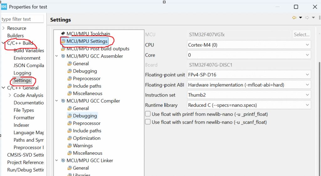
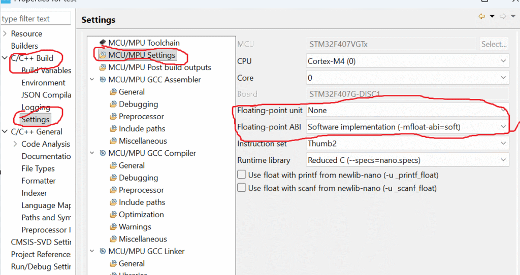
    Step 1: Right-click Your Project → Properties

    Step 2: Go to

    C/C++ Build → Settings → MCU Settings
    

    Make sure these settings are correct:

    • Floating Point Unit: FPv4-SP-D16 (for Cortex-M4)
    • Floating Point ABI: Hard

    Internal flags that must appear automatically:

    -mfpu=fpv4-sp-d16
    -mfloat-abi=hard
    

    If you’re using Cortex-M7, expect:

    -mfpu=fpv5-sp-d16
    -mfloat-abi=hard
    

    If these are wrong…

    You will get typical fpu errors like:

    • unexpected NaN
    • wrong floating-value output
    • HardFault on floating math
    • slow float performance

    Fixing the flags eliminates these issues instantly.

    3. Ensure FPU Is Enabled in system_stm32xxxx.c

    Even if CubeMX should do this automatically, it sometimes doesn’t.

    Open:

    system_stm32f4xx.c
    system_stm32f7xx.c
    system_stm32h7xx.c
    

    Look for:

    SCB->CPACR |= (0xF << 20);   // Enable CP10 + CP11
    

    If it’s missing, add this line inside SystemInit() before calling HAL functions.

    This prevents the common error:

    warning “FPU is not initialized”

    4. Avoid Using Floats Before SystemInit()

    Many beginners accidentally use float operations inside:

    • constructor of a global object
    • static initializers
    • early Reset_Handler code
    • before HAL_Init()

    This leads to runtime fpu errors.

    Fix:

    Make sure floating-point math happens after:

    HAL_Init();
    SystemClock_Config();
    

    5. Fix HardFault from Floating Point Use in FreeRTOS

    If you’re using FreeRTOS with STM32, you must enable FPU support for tasks.

    Add:

    configUSE_TASK_FPU_SUPPORT 2
    

    Or create tasks with:

    xTaskCreate(taskFunc, "task", stack, NULL, priority, &handle);
    

    FreeRTOS will automatically:

    • save/restore FPU registers
    • prevent task-switch corruption
    • avoid NaN randomness

    Without this, multiple tasks fight for the same FPU, causing floating-point bugs.

    6. Clean and Rebuild Your Project

    After enabling FPU:

    • Project → Clean
    • Project → Build

    STM32CubeIDE sometimes keeps old flags; a full clean ensures the new settings apply.

    7. Test Floating Point Output

    Add a simple test:

    float a = 10.5f;
    float b = 3.2f;
    float c = a * b;
    
    printf("FPU Test: %f\n", c);
    

    If output is correct and no warning appears, you’ve solved the issue.

    Why you see the warning (short):

    The compiler is telling you that your project is set to use the processor’s hardware FPU, but your code never enables (initializes) it. If you run floating-point code before the FPU is enabled, the CPU can raise a fault.

    Quick step-by-step fix (STM32CubeIDE):

    1. Right-click your project → Properties.
    2. Open C/C++ Build → Settings.
    3. Under Tool Settings, find MCU Settings.
    4. Set Floating Point Unit to the correct hardware FPU for your MCU.
    5. Set Floating Point ABI to the matching ABI (usually hard when you use the hardware FPU).
    6. Click Apply and Close.
    7. Do Project → Clean (or clean the build).
    8. Rebuild the project.

    After these steps, either the IDE will add proper FPU init code for you or you’ll know to enable the FPU at startup in your SystemInit() (e.g. by setting CPACR on Cortex-M) before any floating-point operations run.
    Fixing FPU Errors in STM32CubeIDE
    Fixing FPU Errors in STM32CubeIDE

    Common Causes of FPU Errors

    Let’s break down the real reasons behind fpu warning fix requirements.

    1. FPU not enabled in the microcontroller startup code

    On Cortex-M4, M7, R5, or A-series processors, the FPU must be manually enabled.

    If not, you’ll see:

    • weird computation results
    • hard faults
    • NaN values
    • compiler warnings
    • runtime messages like warning “FPU is not initialized”

    2. Compiler flags mismatch

    On embedded systems, these flags matter:

    -mfpu=fpv4-sp-d16
    -mfloat-abi=hard
    

    If you compile with FPU support but the hardware lacks it, the program crashes.
    If the hardware supports FPU but compiler doesn’t use it, you get slow code or warnings.

    3. OS not initializing FPU during context switching

    In RTOS systems like:

    • FreeRTOS
    • QNX
    • ThreadX
    • Zephyr

    …each task must save/restore FPU registers.
    If not, FPU corruption occurs.

    4. Using floating values before startup completes

    Some developers accidentally call floating functions inside:

    • early boot
    • before system init
    • inside interrupts

    That leads to fpu errors.

    5. Incorrect exception or lazy stacking settings

    For example, on ARM:

    • enabling lazy FPU stacking incorrectly
    • disabling automatic FP context saving

    …triggers random crashes.

    Signs That You’re Facing FPU Problems

    Here’s how you know you need an fpu warning fix:

    • your program runs but produces incorrect float values
    • occasional crashes when using math functions
    • system gives warning “FPU is not initialized”
    • compiler prints FPU mismatch warnings
    • enabling or disabling FPU changes program behavior
    • DSP code runs extremely slow

    If any of these sound familiar, the next sections will help you fix it.

    How to Fix FPU Warnings (Step by Step)

    Let’s walk through the most common fpu warning fix steps.

    This works for ARM Cortex (M0+, M3, M4, M7, A-series) and most embedded platforms.

    1. Enable FPU in Startup Code

    For most ARM Cortex-M4/M7 microcontrollers, add this:

    SCB->CPACR |= (0xF << 20);    // Enable CP10 and CP11 (FPU)
    

    This registers block controls the CPU’s FPU access.

    After enabling:

    • flush caches
    • set CONTROL register if needed
    • call SystemInit()

    If this isn’t done, you’ll keep seeing warning “FPU is not initialized”.

    2. Fix Compiler Flags

    For Cortex-M4F or M7F:

    -mfpu=fpv4-sp-d16
    -mfloat-abi=hard
    

    For Cortex-A processors:

    -mfpu=neon-fp-armv8
    -mfloat-abi=hard
    

    If you choose the wrong option, GCC throws:

    • “FPU not supported on this architecture”
    • “FPU instructions generated but target does not support FPU”

    Quick rule:

    HardwareCompiler Flag
    Cortex-M0/M3No FPU; disable FPU
    Cortex-M4Ffpv4-sp-d16
    Cortex-M7Ffpv5-sp-d16
    Cortex-Aneon-fp

    3. OS/RTOS Must Manage FPU Context

    In systems like FreeRTOS:

    You must enable:

    configUSE_TASK_FPU_SUPPORT
    

    Otherwise:

    • tasks overwrite each other’s float registers
    • random NaN values appear
    • fpu errors show up under load

    4. Do Not Use Float in Early Boot

    The FPU is usually disabled before system startup.

    Avoid using floating point in:

    • Reset handler
    • Early init functions
    • Bare-metal interrupt handlers

    If you must use it, initialize the FPU first.

    5. Disable or Adjust Lazy FPU Stacking

    Lazy stacking is a power optimization.
    But on some MCUs, it triggers weird issues.

    To disable:

    FPU->FPCCR &= ~(FPU_FPCCR_LSPEN_Msk);
    

    If you experience random hard faults, try toggling lazy stacking.

    FPU Errors During Runtime: What They Really Mean

    Even after initialization, you may face runtime fpu errors like:

    • invalid operation
    • divide by zero
    • underflow
    • overflow
    • inexact result

    These are normal floating-point exceptions.

    Example:

    float x = 1.0 / 0.0;   // Inf
    float y = 0.0 / 0.0;   // NaN
    

    How to debug:

    • print float values
    • check stack corruption
    • inspect FPU registers (S0–S31)
    • check your ABI settings

    Practical Example: Eliminating the FPU Initialization Warning

    Let’s fix the exact error:

    warning “FPU is not initialized”

    Cause:
    Code uses floats before FPU is enabled.

    Fix:
    Enable FPU at the very start of SystemInit.

    void SystemInit(void)
    {
        SCB->CPACR |= (0xF << 20);    // FPU enable
        __DSB();
        __ISB();
    }
    

    Now the warning disappears.
    And your float math becomes faster, correct, and stable.

    FPU Warning Fix in Linux / QNX / Android Systems

    Sometimes the warning comes not from bare metal, but from OS logs.

    Why it happens:

    • kernel doesn’t initialize thread FP state
    • user-space app uses floating point before kernel setup
    • context switching issues

    Fix:

    On QNX or Linux, ensure your thread creates an FP context:

    pthread_attr_setfp(regs, PTHREAD_FP_ENABLE);
    

    Some OSes call it “VFP context” instead of FPU.

    How to Avoid FPU Errors in the Future

    Here are practical tips:

    Always match your toolchain flags to your CPU

    Check the datasheet.

    Enable FPU before using floats

    Do it in SystemInit.

    Avoid floats in interrupts

    Use fixed-point instead.

    Test with edge cases

    Division by zero
    Very small numbers
    Very large numbers

    Keep RTOS FPU context switching enabled

    This prevents cross-task corruption.

    Beginner vs. Experienced Developer Understanding

    Here’s how different developers see the issue.

    Beginners

    • see the warning
    • google it
    • try random fixes
    • still face errors

    Experienced developers

    • check CPU architecture
    • verify compiler flags
    • check startup code
    • inspect context switching

    But now, after this guide, you’ll think like the second group.

    FPU Warning Fix & FPU Errors

    Q1. What is the simplest fix for “warning FPU is not initialized”?
    Enable the FPU in startup code using CPACR.

    Q2. Will enabling FPU break anything?
    No. If your CPU has an FPU, enabling it only improves performance.

    Q3. Why do I get FPU errors only sometimes?
    Usually due to RTOS tasks not saving/restoring FPU registers.

    Q4. Why does float computation produce random values?
    Because FPU registers were overwritten by another task or interrupt.

    Q5. Can an MCU run without FPU enabled?
    Yes, but float operations become slow and warnings appear.

    Q6. Why does enabling lazy stacking cause random crashes?
    Some MCUs have silicon bugs related to it.

    Q7. Do Cortex-M0/M3 have FPU?
    No. Never compile them with FPU flags.

    Q8. What causes floating-point divide-by-zero errors?
    Normal IEEE-754 behavior; not a hardware issue.

    Q9. My compiler shows FPU mismatch warnings. What now?
    Fix your -mfpu and -mfloat-abi flags.

    Q10. Can I completely avoid FPU errors?
    Yes, by initializing FPU properly and using correct compiler flags.

    If you’re learning C programming and want to strengthen your fundamentals before practicing Structures and Unions Interview Questions, you should explore this detailed beginner-friendly guide on structures: Structures in C – Complete Guide
    It explains structure syntax, memory layout, padding, nesting, and real-world examples in a very simple way. Reading this will give you a strong foundation before jumping into advanced interview questions.

    Conclusion: You Can Now Fix Any FPU Warning

    You now understand:

    • what the FPU is
    • why fpu errors appear
    • how to solve fpu warning fix issues
    • how to fix warning “FPU is not initialized”
    • how to configure compiler flags
    • how to avoid problems in RTOS

    Whether you’re a beginner or an experienced embedded developer, this guide covers everything you need to solve floating-point issues confidently.

    FAQ : PU Warning Fix & FPU Errors

    1. What does “FPU Warning Fix” actually mean in STM32 or embedded projects?

    FPU Warning Fix simply means your compiler is alerting you that hardware floating-point instructions are enabled, but your startup code has not initialized the FPU yet. If you use floating-point operations without enabling the FPU, your MCU can crash due to a UsageFault.

    2. Why do FPU errors happen in ARM Cortex-M processors?

    FPU errors occur when:
    FPU hardware is enabled in project settings
    But FPU is not activated in CPACR register
    Or floating-point ABI does not match compiler flags
    This mismatch leads to NOCP faults, crashes, or undefined behavior.

    3. How do I fix FPU warnings in STM32CubeIDE?

    You can solve the warning by:
    Enabling the correct FPU type (e.g., FPv4-SP-D16).
    Selecting the correct floating-point ABI (Hard or SoftFP).
    Initializing CP10/CP11 in SystemInit() before using floats.
    Cleaning and rebuilding the project.

    4. Do I need to enable the FPU manually in code?

    Yes if your startup file does not handle it automatically.
    You must set CPACR bits for CP10 and CP11. Without this, the processor cannot execute any floating-point instructions, causing exceptions.

    5. Why does my project crash when using float or double?

    This happens when FPU instructions are generated, but the processor does not have permission to execute them. The CPU then raises a UsageFault, commonly due to:
    FPU not initialized
    Wrong ABI
    Wrong compiler flags
    RTOS not handling FPU context switching

    6. What FPU settings should I select in STM32CubeIDE?

    For most Cortex-M4/M7 MCUs:
    Floating Point Unit: FPv4-SP-D16 / FPv5
    Floating Point ABI: Hard (recommended)
    SoftFP can be used, but code will be slower.

    7. How does improper FPU configuration affect performance?

    Incorrect FPU setup forces the compiler to use software-based emulation for floating-point operations. This increases CPU cycles drastically, slows application performance, and can create unexpected delays.

    8. Can RTOS users face FPU errors more often?

    Yes. RTOS switches context between tasks.
    If the RTOS does not save/restore FPU registers correctly, tasks using floating-point variables may corrupt the FPU state, causing random crashes or hard faults.

    9. What is the best way to avoid FPU errors in new projects?

    Follow this checklist:
    Choose correct FPU + ABI settings
    Initialize CPACR early
    Avoid floating-point operations inside ISRs
    Verify your RTOS supports FPU context switching
    Test float operations under debugger

    10. How do I verify my FPU is working correctly?

    You can debug by checking:
    CPACR register (CP10 & CP11 bits = 0xF)
    No NOCP bit set in UsageFault Status Register
    Simple float operations execute without exception
    If all checks pass, your FPU is fully enabled and stable.
  • STM32 Cube IDE Tutorial for Beginners: Master Step-by-Step Guide to Start STM32 Programming

    Master STM32 programming with this STM32 Cube IDE tutorial. Learn setup, code, debugging, pros, cons, advanced features in one beginner guide

    If you’ve ever wanted to get started with microcontroller programming, this STM32 Cube IDE tutorial is the perfect place to begin. Think of it like your friendly guide to understanding how STM32 development really works — no fluff, no confusion, just hands-on learning.

    Let’s grab a cup of coffee and dive into what STM32 Cube IDE is, why it’s awesome, and how you can build your first embedded project with it.

    Introduction of STM32 Cube IDE tutorial

    What is STM32 Cube IDE?

    Before we go deep into the STM32 Cube IDE tutorial, let’s talk about what it actually is.

    STM32 Cube IDE is an integrated development environment (IDE) from STMicroelectronics designed for STM32 microcontrollers. It combines STM32CubeMX (the configuration tool) and Eclipse-based IDE into one complete platform.

    In simple terms, it helps you write, compile, debug, and flash code to your STM32 board — all in one place.

    That’s why in this STM32 Cube IDE tutorial, you’ll see how it takes care of everything from pin configuration to code generation.

    Why Use STM32 Cube IDE?

    If you’re wondering why developers love STM32 Cube IDE, here’s why it’s a game-changer:

    • All-in-one tool – You don’t need separate software for configuration, coding, and debugging.
    • Hardware abstraction – You can focus on logic instead of hardware complexity.
    • STM32CubeMX integration – Automatically generates initialization code for GPIO, UART, I2C, SPI, ADC, and more.
    • Built-in debugger – Works directly with ST-Link or J-Link.

    This STM32 Cube IDE tutorial focuses on helping you make the most of these features even if you’re just starting out.

    What You’ll Need

    To follow this STM32 Cube IDE tutorial, here’s your starter pack:

    1. An STM32 development board (like STM32F4 or STM32F103 “Blue Pill”).
    2. A USB cable to connect the board.
    3. STM32 Cube IDE installed on your computer.
    4. Basic knowledge of C programming (don’t worry, nothing advanced).

    If you’re ready with these, let’s jump into your first STM32 Cube IDE tutorial project.

    Step-by-Step: Creating Your First STM32 Project

    This part of the STM32 Cube IDE tutorial walks you through building a simple “Blink LED” program — the classic way to start embedded programming.

    Step 1: Open STM32 Cube IDE

    Once installed, launch STM32 Cube IDE. You’ll see a workspace selection popup. Choose a folder where your projects will be stored.

    Step 2: Create a New STM32 Project

    Click File → New → STM32 Project.
    You can either:

    • Select your STM32 chip manually (like STM32F103C8T6), or
    • Choose your board directly (for example, “NUCLEO-F401RE”).

    This STM32 Cube IDE tutorial uses the board-based approach since it automatically loads pin mappings.

    Step 3: Configure the Microcontroller

    Here’s where STM32CubeMX comes in. You’ll see a graphical pinout view.

    • Click on PA5 (or LED pin) and set it as GPIO Output.
    • Go to Clock Configuration to set the clock frequency.
    • Then click Project → Generate Code.

    You’ve just completed one of the most important parts of this STM32 Cube IDE tutorial — automatic code generation.

    Step 4: Write Your Code

    Now, open main.c inside your project. You’ll see a function called main().
    Replace the user section with this:

    while (1)
    {
      HAL_GPIO_TogglePin(GPIOA, GPIO_PIN_5);
      HAL_Delay(500);
    }
    

    This will blink your LED every 500 ms — simple, right? That’s the magic of STM32 programming.

    Step 5: Build and Flash

    Click the Hammer icon to build your project.
    Then, click the Play (Debug) button to upload the program to your STM32 board.
    If all goes well, your LED will start blinking — your first success in this STM32 Cube IDE tutorial!

    Understanding What Happened

    Let’s break down what this STM32 Cube IDE tutorial just did:

    • The HAL (Hardware Abstraction Layer) handled all low-level code.
    • CubeMX configured the GPIO pin automatically.
    • You only wrote the logic.

    This is the power of STM32 Cube IDE — it removes the complexity while letting you focus on functionality.

    Common Tips for Beginners

    Even though this STM32 Cube IDE tutorial is beginner-friendly, here are a few pro tips:

    1. Always check Project → Properties → MCU Settings if something doesn’t build.
    2. Use HAL_Delay() only for testing; for real-time control, use timers.
    3. Read STM32 Reference Manual to understand peripherals better.
    4. Don’t skip the debugger — you can pause, inspect variables, and watch your code in action.

    What’s Next After This STM32 Cube IDE Tutorial?

    Once you’ve nailed the basics, here’s how to level up:

    • Try UART communication to send data to your PC.
    • Learn ADC to read sensor values.
    • Explore PWM to control motors or LEDs.
    • Dive into RTOS with STM32CubeIDE FreeRTOS integration.

    Every new project you build strengthens your understanding of embedded C and hardware.

    Advantages of STM32 Cube IDE

    Why should you choose this IDE for your next embedded project? This STM32 Cube IDE tutorial highlights its key advantages:

    1. Integrated toolchain — You can configure peripherals, write code, and flash firmware without switching tools.
    2. HAL support — The Hardware Abstraction Layer makes code reusable and easy to maintain.
    3. Auto code generation — STM32CubeMX handles pin setup and initialization code.
    4. Powerful debugger — Supports breakpoints, variable watch, memory inspection, and live expressions.
    5. Cross-platform — Works on Windows, Linux, and macOS.
    6. Free and official — Supported directly by STMicroelectronics.

    These features make it perfect for both beginners and professionals — which is why this STM32 Cube IDE tutorial is the go-to starting point.

    Disadvantages of STM32 Cube IDE

    Like every tool, it’s not flawless. Let’s be honest in this STM32 Cube IDE tutorial about its downsides:

    1. Heavy on resources – It can feel slow on older PCs.
    2. Complex for first-time users – So many menus can overwhelm beginners.
    3. Limited customization – Compared to VS Code or Keil uVision.
    4. Occasional debugging issues – ST-Link drivers sometimes need reinstallation.

    Still, for free software that handles configuration, build, and debugging — the pros outweigh the cons.

    Advanced Features of STM32 Cube IDE

    Once you’re comfortable with the basics, this STM32 Cube IDE tutorial encourages you to explore advanced features:

    1. FreeRTOS Integration – Add real-time multitasking with one click.
    2. Memory and CPU Analysis – Visual graphs for stack usage and runtime stats.
    3. Peripheral Register View – Inspect hardware registers during debugging.
    4. Code Profiling – Find performance bottlenecks in your embedded code.
    5. Firmware Package Manager – Download HAL libraries and middleware updates directly.
    6. Multi-core debugging – For advanced STM32H7 or dual-core systems.

    Each of these advanced features expands what you can build with STM32 Cube IDE — from IoT devices to complex real-time systems.

    Tips to Get Better at STM32 Programming

    To wrap up this STM32 Cube IDE tutorial, here are some helpful tips:

    • Learn how to use STM32CubeMX effectively — it saves hours of manual setup.
    • Read the Reference Manual for your MCU to understand peripheral registers.
    • Use breakpoints and watch windows instead of printf for debugging.
    • Gradually explore DMA, Timers, UART, SPI, and ADC peripherals.
    • Save and back up your workspace regularly.

    Step-by-Step: Your First STM32 Project

    Let’s get practical! This STM32 Cube IDE tutorial will walk you through making your first “Blink LED” project.

    Step 1: Open STM32 Cube IDE

    Launch STM32 Cube IDE and choose your workspace (the folder where your projects will be saved).

    Step 2: Create a New STM32 Project

    Go to File → New → STM32 Project.
    Select your MCU or board (like STM32F103C8T6 or NUCLEO-F401RE).
    Name your project and click Finish.

    Step 3: Configure the Board

    In the pinout view:

    • Click PA5 (for onboard LED) and set it as GPIO_Output.
    • Go to Clock Configuration → set your desired frequency (e.g., 72 MHz).
    • Click Project → Generate Code.

    Now the IDE generates all initialization code automatically — that’s one of the coolest parts of this STM32 Cube IDE tutorial.

    Step 4: Write the Blink Code

    Open Core/Src/main.c and modify it like this:

    #include "main.h"
    
    int main(void)
    {
      HAL_Init();
      SystemClock_Config();
      MX_GPIO_Init();
    
      while (1)
      {
        HAL_GPIO_TogglePin(GPIOA, GPIO_PIN_5);
        HAL_Delay(500);
      }
    }
    

    Step 5: Build and Upload

    Click the hammer icon (Build Project) to compile your code, then click the green bug icon (Debug) to flash your firmware onto the STM32 board.

    If everything is connected properly, your onboard LED should start blinking — proof that your configuration, code, and hardware setup are all working perfectly.

    Congratulations — you’ve successfully completed your first STM32 Cube IDE tutorial project!

    Now that your first STM32 program is running, you can explore more advanced topics like integrating security features in embedded systems. For example, learn how to add encryption and secure communication in your next project with this detailed guide on using a cryptographic library with STM32.

    Debugging in STM32 Cube IDE

    Let’s take this STM32 Cube IDE tutorial one step deeper — debugging. Debugging is where you watch your code think.

    Example C Code for Debugging

    Here’s a simple code to demonstrate debugging:

    #include "main.h"
    
    int counter = 0;
    
    int main(void)
    {
      HAL_Init();
      SystemClock_Config();
      MX_GPIO_Init();
    
      while (1)
      {
        counter++;
        HAL_GPIO_TogglePin(GPIOA, GPIO_PIN_5);
        HAL_Delay(500);
      }
    }
    

    Steps to Debug of STM32 Cube IDE

    1. Click Debug (green bug icon).
    2. Once in Debug Mode:
      • Set a breakpoint on the line counter++; by clicking beside it.
      • Click Resume (F8) to run the program.
      • When it stops at the breakpoint, hover over counter to see its value.
      • Press Step Over (F6) to run line-by-line.

    This helps you observe variables in real-time — exactly what makes STM32 Cube IDE debugging so powerful.

    Conclusion of STM32 Cube IDE tutorial

    So, that’s the complete STM32 Cube IDE tutorial — beginner-friendly, practical, and totally hands-on. You’ve learned how to:

    • Set up STM32 Cube IDE
    • Configure pins using STM32CubeMX
    • Write and flash your first embedded program

    Once you complete this STM32 Cube IDE tutorial, you’ll realize how easy it is to move from simple code to full embedded applications.

    The world of STM32 microcontrollers is huge, and this STM32 Cube IDE tutorial is just your first step into it. Keep experimenting, stay curious, and you’ll soon be creating advanced STM32 projects with confidence.

    Frequently Asked Questions (FAQ) on STM32 Cube IDE Tutorial

    1. What is STM32 Cube IDE and why should I use it?

    STM32 Cube IDE is an official, free development platform from STMicroelectronics that combines STM32CubeMX, a C/C++ compiler, and a powerful debugger into one tool.
    If you’re learning embedded programming, this STM32 Cube IDE tutorial is the easiest way to start because it simplifies hardware configuration, code generation, and debugging — all in one environment.

    2. Is STM32 Cube IDE beginner-friendly?

    Yes! That’s the best part. This STM32 Cube IDE tutorial was written with beginners in mind. The IDE provides graphical pin configuration, code auto-generation, and HAL libraries — so even if you’re new to embedded C programming, you can quickly understand and build working projects without diving deep into hardware registers right away.

    3. What is the difference between STM32CubeMX and STM32 Cube IDE?

    STM32CubeMX is the configuration tool — it lets you set up pins, clocks, and peripherals graphically.
    STM32 Cube IDE, on the other hand, is a full integrated development environment (IDE) where you write, compile, and debug your code.
    This STM32 Cube IDE tutorial shows you how both tools work together: CubeMX handles configuration, and Cube IDE handles coding and debugging.

    4. Can I use STM32 Cube IDE for any STM32 microcontroller?

    Yes. The STM32 Cube IDE supports all STM32 series — including STM32F0, F1, F4, L4, H7, and G0.
    Whether you have a Blue Pill board, a NUCLEO board, or a custom STM32 board, this STM32 Cube IDE tutorial will guide you through creating and debugging your projects easily.

    5. What programming language is used in STM32 Cube IDE?

    The STM32 Cube IDE primarily uses Embedded C and C++ for coding STM32 microcontrollers.
    You can also mix C and assembly if needed.
    As explained in this STM32 Cube IDE tutorial, beginners should start with C using the HAL (Hardware Abstraction Layer) before moving to low-level or register-level programming.

    6. How do I debug code in STM32 Cube IDE?

    Debugging is one of the most powerful features covered in this STM32 Cube IDE tutorial.
    You can set breakpoints, watch variable values in real-time, inspect memory, and step through your code using the ST-Link debugger.
    It’s a hands-on way to understand what your code is doing on the microcontroller, line by line.

    7. Does STM32 Cube IDE support FreeRTOS?

    Absolutely! STM32 Cube IDE has built-in FreeRTOS integration.
    With just a few clicks, you can enable multitasking, manage threads, and create real-time embedded systems.
    This STM32 Cube IDE tutorial is a great foundation before diving into advanced RTOS topics.

    8. What are the advantages of using STM32 Cube IDE over Keil or IAR?

    Unlike Keil or IAR, STM32 Cube IDE is completely free and officially supported by STMicroelectronics.
    It integrates STM32CubeMX, has no code size limitation, supports FreeRTOS, and offers powerful debugging tools.
    This STM32 Cube IDE tutorial focuses on how you can achieve professional-level results without any paid license.

    9. Can STM32 Cube IDE be used on Linux or macOS?

    Yes. One of the key benefits mentioned in this STM32 Cube IDE tutorial is cross-platform compatibility.
    It runs smoothly on Windows, Linux, and macOS, making it perfect for developers on any system.

    10. Where can I learn more about STM32 projects after this tutorial?

    Once you complete this STM32 Cube IDE tutorial, you can explore more embedded concepts like:

    • Using a cryptographic library with STM32
    • Communication protocols (UART, SPI, I2C)
    • ADC and PWM applications
    • FreeRTOS-based multitasking
      Each new project helps deepen your understanding of STM32 microcontrollers and embedded C programming.

    11. What hardware do I need for following this STM32 Cube IDE tutorial?

    You’ll need an STM32 development board (like STM32F103C8 “Blue Pill” or NUCLEO-F401RE), a USB cable, and an ST-Link programmer/debugger.
    That’s all! The rest of the setup — code, drivers, and configuration — is done within STM32 Cube IDE itself.

    12. Can I use STM32 Cube IDE without coding?

    Not completely, but thanks to STM32CubeMX, you can generate most of the setup code automatically.
    This STM32 Cube IDE tutorial shows you how to configure peripherals graphically and then tweak only the logic part of your program — so even if you’re not an expert coder, you can still build working embedded systems.

    13. What are some common issues faced by beginners?

    Beginners often face errors related to:

    • Missing ST-Link drivers
    • Wrong clock configuration
    • Incorrect pin mapping
    • Build errors after code generation
      This STM32 Cube IDE tutorial explains these issues and how to fix them step-by-step, so you don’t get stuck during setup or debugging.

    14. Is STM32 Cube IDE suitable for professional embedded projects?

    Yes. Many professionals use STM32 Cube IDE in automotive, industrial, and IoT applications.
    It’s not just for students — it offers advanced tools like code profiling, register-level debugging, and FreeRTOS support, as mentioned in this STM32 Cube IDE tutorial.

    15. How can I optimize code performance in STM32 Cube IDE

    You can enable optimization levels in Project Properties → C/C++ Build → Settings → Optimization.
    This STM32 Cube IDE tutorial recommends starting with -O1 or -O2 for faster execution while keeping debugging easier.
    For performance-critical code, consider using DMA and interrupts instead of delays.

    Bonus Tip:

    If you’re serious about STM32 development, check out this related guide —
    👉 Cryptographic Library with STM32 — it shows how to add security and encryption to your embedded systems