Learn drone anatomy for programmers explained from scratch motors, ESCs, flight controllers, sensors, MAVLink, and PID loops all explained in plain language so your code actually makes sense.
If you have ever stared at a drone and thought “I want to program this thing, but I have no idea what I am looking at” this guide is for you.
Most tutorials online assume you either already know hardware or do not care about it. Neither of those is helpful if you want to actually write code that controls a physical flying machine. You need to understand the drone’s body before you can talk to it intelligently. Think of it like learning API docs before you start writing integrations. You would not call endpoints blindly without knowing what data goes in and what comes out.
Drone anatomy for programmers explained properly means understanding not just the names of parts, but why those parts exist, how they communicate, and what your code is actually telling them to do. That is what this article covers from the ground up.
Why Programmers Need to Understand Drone Hardware
Here is the thing most drone programming tutorials skip: you can copy-paste flight code all day and still produce a drone that flies erratically, crashes, or simply does not do what you intended. The reason is almost always a disconnect between the programmer and the physical machine.
When you write drone.move_forward(speed=50), something physical is happening. Motors are spinning at different speeds. A sensor is correcting for wind drift. A PID controller is making micro-adjustments 400 times per second. If you do not know what those layers look like, debugging is basically guesswork.
Understanding drone hardware components for developers is not about becoming a mechanical engineer. It is about knowing your interface. You do not need to build a motor from scratch, but you do need to understand that a motor has a maximum RPM, that it responds to PWM signals, and that asking it to do too much will cause brownouts or overheating.
This is the same reason good backend developers understand database internals even when using an ORM. The abstraction is useful, right up until it is not.
The Big Picture: Drone System Architecture
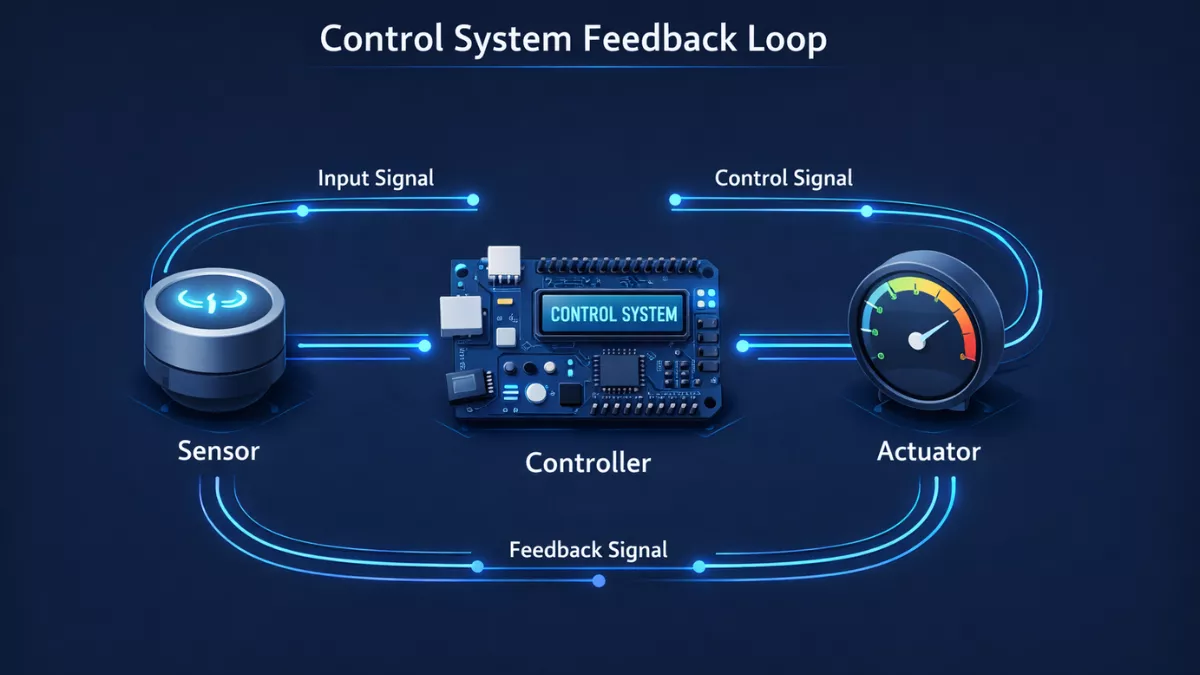
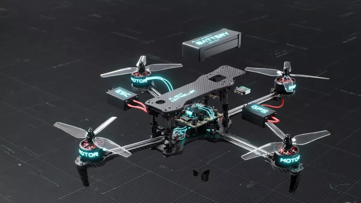
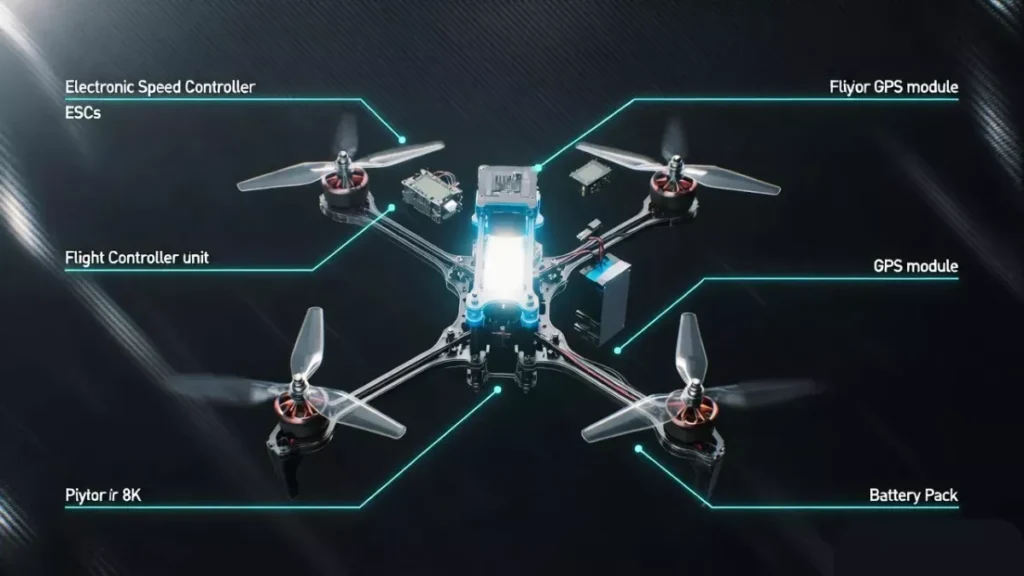
Before diving into individual parts, zoom out and look at the overall system. A drone is essentially a distributed embedded system. Multiple sensors feed data into a central flight controller, which makes decisions and sends commands to motors via speed controllers. Optionally, a companion computer runs your higher-level code and talks to the flight controller through a communication protocol.
Here is a simplified view of the data flow:
Sensors → Flight Controller → ESCs → Motors → Physical Motion
And in parallel:
Your Code → Companion Computer → MAVLink/Serial → Flight Controller → ESCs → Motors
Every component in that chain matters. Drop any one of them and the drone either does not fly or flies unpredictably. As someone writing code for drones, you sit in the middle of that chain, and understanding every node makes you a dramatically better programmer.
1. The Frame: The Skeleton Your Code Lives On
The frame is the physical structure that holds everything together. Most programmers ignore it completely, but the frame actually affects your code in surprising ways.
Frame Configuration and Motor Layout
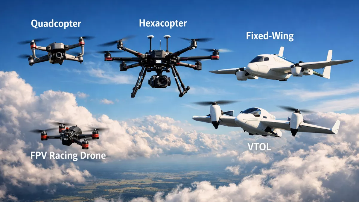
Drones most commonly come in three configurations: tricopter (3 motors), quadcopter (4 motors), hexacopter (6 motors), and octocopter (8 motors). The vast majority of drones developers work with are quadcopters, and those come in two standard layouts: X configuration and + configuration.
In X configuration, the drone’s nose points between two arms. In + configuration, one arm points straight forward. This changes which motor combination the flight controller uses for forward pitch, and it also changes how your telemetry data maps to physical orientation when you are debugging flight logs.
When you work with a flight controller or autopilot system like ArduPilot or PX4, you have to tell it the frame type during configuration. Get this wrong in your setup code and the drone will flip on takeoff.
Frame Size and Its Coding Implications
Frame size is measured in millimeters diagonally between motors, so a 250mm quad has motors 250mm apart corner to corner. Larger frames carry heavier payloads including bigger cameras, more sensors, or companion computers. They also have more rotational inertia, which means the PID tuning parameters you use in your flight controller configuration need to be different.
If you are writing code that auto-tunes PID values, or if you are configuring an existing autopilot, frame size is one of the inputs you need. It is not just a hardware detail.
2. Motors: What Your ESC Commands Actually Do
Motors are where electrical signals become physical rotation. For programmers, understanding motors is about understanding the relationship between your commands and actual angular velocity.
Brushless DC Motors: How They Work
Almost every serious drone uses brushless DC (BLDC) motors. Unlike brushed motors, BLDC motors do not have physical contact between the rotating and stationary parts. Instead, the speed controller electronically commutates the three-phase power to spin the motor.
What this means for your code is that you never directly command a motor. You command an ESC, which interprets your signal and applies the appropriate voltage phasing to the motor. The motor’s actual behavior is one abstraction layer below your code.
KV Rating: The Spec That Matters for Developers
Motor KV rating tells you how many RPM the motor spins per volt of input with no load. A 2300KV motor on a 3S battery (11.1V nominal) spins at roughly 25,000 RPM unloaded.
Why does this matter to you as a programmer? Two reasons.
First, when you are doing thrust calculations or simulations, KV directly feeds into your motor model. If you are writing a physics-based simulation or a software-in-the-loop (SITL) test environment, you need this number.
Second, KV affects how quickly the motor responds to throttle changes. Higher KV motors react faster, which matters for control loop tuning. If your PID parameters were written for a low-KV motor and you swap to a high-KV motor, your code will become unstable without retuning.
Motor Direction: CW and CCW
On a quadcopter, motors spin in alternating directions. Two spin clockwise (CW) and two spin counterclockwise (CCW). This is not arbitrary. The opposing torque forces cancel out, preventing the drone from spinning uncontrollably on its yaw axis.
In code, when you issue a yaw command, the flight controller speeds up all the CW motors slightly and slows down all CCW motors (or vice versa), creating a net torque that rotates the airframe. If your motor order or direction is wrong in the flight controller configuration, yaw commands will do unexpected things. Diagnosing this almost always comes back to motor mapping.
3. ESCs: The Interface Between Code and Motors
The Electronic Speed Controller (ESC) is arguably the most important hardware interface for drone programmers to understand. Your flight controller sends signals to ESCs, and ESCs translate those signals into the three-phase AC power that spins brushless motors.
ESC Protocols: The Language Your Code Uses
This is where drone hardware gets genuinely interesting from a programming perspective. ESCs do not just accept a generic signal. They accept specific protocols, and the protocol you use has real implications for your system’s performance.
PWM (Pulse Width Modulation): The oldest and most universal protocol. A 1ms pulse means minimum throttle, a 2ms pulse means maximum, and everything in between is proportional. The issue is refresh rate, typically limited to 50Hz, which means the ESC only receives a new command 50 times per second. For a control loop running at 400Hz, that is a severe bottleneck.
OneShot125 and OneShot42: These are faster versions of PWM. OneShot125 runs pulses between 125 and 250 microseconds (8x faster than PWM). OneShot42 is even faster. They sync the ESC update rate to the flight controller’s loop rate, dramatically reducing latency.
DSHOT: This is a fully digital protocol, and it is the modern standard. Unlike PWM which uses pulse timing and is vulnerable to noise and drift, DSHOT sends actual binary packets. DSHOT300, DSHOT600, and DSHOT1200 refer to the bitrate in kbits/second. With DSHOT, you also get bidirectional communication meaning the ESC can send RPM telemetry back to the flight controller, which is extremely useful for RPM-based filtering and control.
KISS and BLHeli protocols: These are ESC firmware-level protocols that add configuration and telemetry capabilities. ESC configuration (like motor direction, timing, and demag settings) can be done programmatically if you implement these protocols in your software.
For a programmer choosing a protocol: use DSHOT if your ESC and flight controller both support it. The digital reliability and bidirectional telemetry are worth it.
ESC Firmware and What You Can Actually Configure
Modern ESCs run firmware like BLHeli_32 or AM32 that you can flash and configure via USB or via a pass-through from the flight controller. If you are building a drone automation system, knowing that ESC firmware parameters like motor timing and PWM frequency are configurable via software is useful. ESC timing affects motor efficiency and heat, and some autopilot configurations involve pushing ESC parameter changes during runtime.
Current, Voltage, and Protecting Your Hardware in Code
ESCs have a continuous current rating and a burst rating. Exceeding continuous ratings for extended periods will cause thermal shutdown or permanent damage. As a drone programmer, this means your code should respect throttle ramp rates and not issue abrupt full-throttle commands, especially during complex maneuvers.
When you write automated flight scripts, smooth throttle transitions are not just about comfortable flight, they are about hardware longevity. Hard throttle spikes also cause voltage spikes that can corrupt flight controller data or trigger brownout detection.
4. Flight Controller: The Brain You Program Against
The flight controller (FC) is the embedded computer that runs the real-time control algorithms keeping your drone stable. This is the most important piece of hardware to understand deeply because most of your code either runs on it or talks to it.
What the Flight Controller Actually Does
Every control loop cycle, the flight controller reads sensor data, runs stabilization algorithms, and outputs motor commands. This happens at rates between 1kHz and 32kHz on modern hardware. At the same time, it manages communication with your ground control station, RC receiver, GPS, and any companion computer you have connected.
Popular flight controllers include the Pixhawk series (which runs ArduPilot or PX4 firmware), Betaflight boards (popular in FPV racing), and various custom boards. Each has different capabilities and different programming interfaces.
Betaflight, ArduPilot, and PX4: What the Difference Means for Your Code
This is something beginners frequently get confused about. The flight controller is hardware, but the firmware running on it defines your programming interface.
Betaflight is optimized for manual FPV flying with extremely fast loop times. Its CLI (Command Line Interface) is accessible via serial and can be scripted. Betaflight is not really designed for autonomous flight it has limited GPS and waypoint capability. Programming against Betaflight usually means configuring its parameters, not running complex autonomous missions.
ArduPilot is the workhorse of autonomous drone programming. It runs on Pixhawk hardware and supports full GPS-based autonomous missions, guided mode control, MAVLink communication, and Python scripting via DroneKit. If you are writing code to make a drone navigate a complex route, avoid obstacles, or run automated inspection tasks, you are probably using ArduPilot.
PX4 is ArduPilot’s main competitor in the autonomous space. It has a more modern software architecture, excellent ROS (Robot Operating System) integration, and is popular in research settings. The MAVSDK library lets you control PX4-based drones in Python, C++, Swift, and Java.
Choosing between ArduPilot and PX4 is often an ecosystem decision. ArduPilot has a larger community and more vehicle types. PX4 is more developer-friendly in terms of code architecture if you want to modify the firmware itself.
PID Controllers: The Algorithm at the Heart of Stability
You will hear PID everywhere in drone programming. PID stands for Proportional, Integral, Derivative, and it is the control algorithm that keeps the drone stable. When you command a 30-degree pitch angle and the drone only achieves 28 degrees, the PID controller calculates the error (2 degrees), adjusts motor speeds to correct it, and keeps doing this hundreds of times per second.
As a programmer, you will interact with PID parameters in several ways. You will configure them in your flight controller settings, you might implement your own PID loops for position control in your companion computer, and you will need to understand them to debug unstable flight behavior.
The three parameters are:
P (Proportional): How aggressively the drone corrects errors. Too high causes oscillation. Too low causes sluggish response.
I (Integral): Corrects for persistent offset errors like steady wind drift. Too high causes slow oscillation. Too low means the drone never fully reaches its target.
D (Derivative): Dampens corrections to prevent overshoot. Too high causes high-frequency vibration. Too low causes wobbling.
PID tuning is part science, part art. Tools like Betaflight’s Blackbox logging and PX4’s Flight Review let you analyze flight data and adjust parameters algorithmically. There are also autotune functions in ArduPilot that can run flight maneuvers and calculate optimal PID values automatically.
Flight Modes and What They Mean for Your Code
Flight controllers support multiple flight modes that define how they interpret commands. This is critical to understand before writing any control code.
Acro (Rate) Mode: Your commands directly set rotation rates. Full pitch stick means spin at X degrees per second. No stabilization. Highest precision but hardest to fly. Most FPV pilots use this.
Angle (Self-Level) Mode: Your commands set a target angle, not a rate. Release the stick and the drone levels itself. Good for beginners and payload drones.
Altitude Hold Mode: The flight controller uses barometric pressure to maintain a constant altitude. Forward/backward commands still work, but the drone does not climb or descend unless you specifically command it.
Loiter/Position Hold Mode: GPS-based position hold. Release all sticks and the drone hovers in place. GPS drift can cause slow wandering, which your position control code needs to handle.
Guided Mode (ArduPilot) / Offboard Mode (PX4): This is the mode your code uses for autonomous control. In Guided/Offboard mode, the flight controller takes movement commands from an external computer via MAVLink or uORB. This is the gateway to writing code that actually makes autonomous decisions.
5. Sensors: The Data Your Code Reads and Trusts
A drone is a sensor-dense machine. Understanding each sensor type, its refresh rate, its error characteristics, and how the flight controller fuses its data is essential for writing reliable autonomous code.
Inertial Measurement Unit (IMU)
The IMU is the most fundamental sensor. It contains an accelerometer and a gyroscope in a single chip. The accelerometer measures linear acceleration (including gravity), and the gyroscope measures angular velocity.
The flight controller reads the IMU at very high rates, often 1kHz or more, and runs a complementary or Kalman filter to estimate the drone’s attitude (roll, pitch, yaw orientation). Without the IMU, the drone cannot stabilize itself at all.
What this means for your code: IMU data is your most immediate sensor reading, but it accumulates error over time (gyroscope drift) and is noisy in the short term. When you read attitude data from the flight controller, understand it has already been filtered and fused. If you are building custom state estimation, you need to implement your own filter on top of raw IMU data.
Temperature affects IMU accuracy. Consumer-grade drones usually do IMU calibration at room temperature. In cold weather operations, expect more drift and potentially more aggressive PID oscillations until the IMU warms up.
Barometric Pressure Sensor
The barometer measures atmospheric pressure to estimate altitude. It is accurate to roughly 10-20cm in calm conditions but is extremely sensitive to prop wash (airflow from the motors blowing into the barometer) and wind gusts.
Flight controllers typically have foam covers over the barometer to reduce prop wash effects. In your code, when you are doing altitude-critical operations like landing on a platform or flying at a fixed height indoors, barometer-based altitude is often not reliable enough. You need to fuse it with other sensors.
GPS: Position Data Your Autonomous Code Depends On
The GPS module gives you latitude, longitude, altitude, and speed. Most drones use an external GPS module mounted on a mast above the frame to get it away from electromagnetic interference from the power system.
GPS accuracy is typically 1-3 meters CEP (Circular Error Probable) with a standard GPS. RTK (Real-Time Kinematic) GPS can get you to centimeter-level accuracy using correction signals from a base station. If you are writing code for precision landing, surveying, or agricultural spraying, RTK GPS is often necessary.
GPS has latency. There is a delay between physical movement and the GPS position update, typically 100-200ms. In high-speed autonomous flight code, you need to account for this lag or your position corrections will always be slightly behind reality. Kalman filter implementations in autopilots do this through GPS-IMU fusion, but custom position controllers need to handle it explicitly.
GPS spoofing and jamming are real concerns for drone security. If you are writing code for critical applications, GPS sanity checking (comparing GPS position with optical flow or other position sensors) adds a layer of protection.
Optical Flow Sensor
An optical flow sensor is basically a downward-facing camera that measures how fast ground features are moving beneath the drone. Combined with a rangefinder for altitude, it gives precise horizontal velocity measurements that GPS cannot provide.
Optical flow is invaluable for indoor flight where GPS is unavailable, and for precise hovering at low altitudes outdoors. The big limitation is that it needs a textured surface to work. Flying over water, sand, or featureless white surfaces gives the optical flow sensor nothing to track, and position estimates degrade rapidly.
In your code, optical flow data typically comes in as velocity measurements in body frame (relative to where the drone is pointing). Transforming these into world-frame velocity requires knowing the drone’s current heading, which comes from the IMU.
Rangefinder and Lidar
Rangefinders measure distance to surfaces below the drone. Ultrasonic rangefinders work well indoors up to about 3-4 meters. Lidar (laser rangefinder) sensors are more accurate, work at greater ranges, and function better outdoors.
For landing code, a rangefinder is practically essential. Using barometer altitude for precision landing introduces enough error that you can easily overshoot by 20-30cm, which is fine on grass but problematic on a landing pad or ship deck.
Rangefinders are also used for terrain following, where the drone maintains a constant height above the ground rather than a constant barometric altitude. Writing terrain-following code requires reading rangefinder data in a tight control loop and adjusting throttle accordingly.
Compass (Magnetometer)
The compass measures the Earth’s magnetic field to determine the drone’s absolute heading. It is critical for GPS-based flight because the GPS tells you where you are but not which way you are facing.
Compass calibration is one of the most common sources of problems in drone programming. Magnetic interference from the power system, motors, and ESCs can overwhelm the compass reading if the magnetometer is too close to these components, which is why GPS modules with integrated compasses are mounted on masts.
In your flight code and configuration, always ensure compass offsets are calibrated before autonomous flights. ArduPilot’s automatic compass learning can help in some cases, but hard iron and soft iron calibrations done on the ground are generally more reliable.
Airspeed Sensor (Fixed-Wing and VTOL)
For fixed-wing drones and VTOL (Vertical Takeoff and Landing) aircraft transitioning to forward flight, an airspeed sensor that measures the pressure differential between pitot tube and static port gives true airspeed measurement. Ground speed from GPS and true airspeed together let you calculate wind speed and direction, which feeds into wind-aware path planning code.
6. Power System: How Voltage and Current Affect Your Code
The power system is easy to overlook from a programming perspective, but it has direct impacts on flight behavior, sensor reliability, and code stability.
LiPo Batteries: Voltage Curves and What They Mean
Lithium Polymer (LiPo) batteries are the standard for drone power. Each cell has a nominal voltage of 3.7V, a fully charged voltage of 4.2V, and a minimum safe voltage of around 3.5V per cell. A 4S battery (4 cells in series) has a nominal voltage of 14.8V.
Here is the critical insight for programmers: a LiPo battery’s voltage drops under load. At full throttle, a 4S battery might read 14.8V at rest but drop to 13.5V under full load. This voltage sag is not just a hardware problem. It affects your motor performance estimates. If you have code that calculates available thrust based on voltage, you need to account for sag under load, not just resting voltage.
More importantly, your flight controller monitors battery voltage and should trigger a low-battery warning or RTL (Return to Launch) failsafe at a configured threshold. Make sure your code handles these failsafes gracefully rather than assuming full power will always be available.
Power Distribution Board (PDB) and Voltage Regulators
The Power Distribution Board takes the battery voltage and distributes it to ESCs and other components. Many modern flight controller stacks integrate the PDB directly. The PDB also provides regulated 5V and 12V rails for the flight controller, servos, and peripherals.
Your companion computer, if you have one, also needs power. Running a Raspberry Pi or NVIDIA Jetson from the drone battery requires a quality BEC (Battery Eliminator Circuit) that provides clean regulated power. Noise on the power rail can cause I2C and SPI sensor communication errors, which show up in your code as sporadic sensor readings or communication timeouts.
Current Sensor and Power Monitor
Most advanced flight controllers include a current sensor that measures how much current the battery is supplying in real time. Combined with voltage measurement, this gives you instantaneous power draw and cumulative mAh consumption.
In your code, mAh consumed is your most reliable battery state metric. Voltage alone is noisy under load. Tracking mAh from a known capacity lets you estimate remaining flight time with much better accuracy. Implementations of battery-aware path planning typically use mAh budgets rather than voltage thresholds.
7. Communication Interfaces: How Your Code Talks to the Drone
This section is purely code-relevant. These are the actual interfaces your software uses.
MAVLink: The Protocol of Drone Autonomy
MAVLink (Micro Air Vehicle Link) is the communication protocol used by ArduPilot and PX4. It is a binary protocol that defines hundreds of message types for everything from requesting telemetry data to sending navigation commands to receiving sensor readings.
When you write Python code using DroneKit or MAVSDK, you are sending and receiving MAVLink messages under the hood. Understanding MAVLink at the packet level is useful when debugging communication issues or when you need to implement custom message types.
Key MAVLink message types you will frequently encounter:
HEARTBEAT: Sent every second by both the ground station and the autopilot. Both sides need to see heartbeats to consider the connection active. Your code must send heartbeats or the autopilot will trigger a communication loss failsafe.
COMMAND_LONG and COMMAND_INT: Used to send commands like DO_SET_MODE, NAV_TAKEOFF, NAV_WAYPOINT, NAV_LAND. COMMAND_INT uses integer coordinates (in degrees * 1e7) which avoids floating-point precision issues for GPS coordinates.
SET_POSITION_TARGET_LOCAL_NED: Used in Guided/Offboard mode to send velocity, position, or acceleration setpoints in local North-East-Down frame. This is the bread and butter of custom autonomous navigation code.
GLOBAL_POSITION_INT: Telemetry message containing current GPS position, altitude, and velocity. Your position monitoring loop reads this constantly.
Serial Communication and Baud Rates
Flight controllers have multiple UART serial ports. Each can be configured to run a different function: MAVLink telemetry, RC receiver input, GPS input, ESC telemetry, or Bluetooth/WiFi module connection.
When connecting a companion computer to a flight controller, you typically use a serial connection at 921600 baud or higher for low-latency communication. Getting the baud rate and flow control settings right in your serial configuration is necessary before MAVLink can work reliably.
ROS and MAVROS for Research Applications
If you are working in a research environment, you will likely encounter ROS (Robot Operating System). ROS provides a publish-subscribe messaging infrastructure that connects different software nodes. MAVROS is a ROS package that acts as a bridge between ROS topics/services and MAVLink, allowing you to write drone control nodes in the familiar ROS paradigm.
With MAVROS, you can subscribe to topics like /mavros/local_position/pose to get position data, publish to /mavros/setpoint_velocity/cmd_vel to command velocity, and use services like /mavros/set_mode to change flight modes. If you are doing drone swarms, sensor fusion research, or computer vision-based navigation, the ROS ecosystem has mature tools that integrate cleanly through MAVROS.
SPI, I2C, and UART: Onboard Sensor Communication
Inside the flight controller, sensors communicate with the main processor via SPI or I2C buses. The IMU typically uses SPI for its high data rate. GPS uses UART. The barometer and compass often use I2C.
This matters if you are adding custom sensors to your drone. Attaching an I2C sensor to the flight controller’s I2C bus is straightforward if the sensor has a driver in ArduPilot or PX4. Writing a custom sensor driver requires implementing the appropriate bus protocol and integrating your readings into the flight controller’s sensor fusion pipeline, which is a non-trivial firmware modification.
8. Radio Control and Telemetry
RC Receivers: The Human Pilot Interface
Even on autonomous drones, an RC receiver is typically present as a safety override mechanism. If your autonomous code behaves badly, a human pilot can take over manually.
RC receivers communicate with flight controllers via several protocols:
PPM (Pulse Position Modulation): Encodes all channels on a single wire sequentially. Simple but limited bandwidth.
SBUS: A digital serial protocol used by Futaba and FrSky systems. Sends 16 channels at 100Hz. Requires signal inversion on some flight controllers.
CRSF (Crossfire): Modern protocol from TBS. Full duplex, ultra-low latency, works over the same long-range radio link as the video feed on FPV systems.
In your flight controller configuration code, you specify the RC protocol and which channels map to which functions (throttle, roll, pitch, yaw, flight mode switch, etc.).
Telemetry Radios
Telemetry radios give you a long-range bidirectional data link between your ground station software and the drone. The SiK radio modems at 915MHz (Americas) or 433MHz (Europe/Asia) are the most common. They connect to a UART on the flight controller and present as a serial port on your laptop, allowing QGroundControl or Mission Planner to communicate with the drone in real time.
For developers, telemetry radios mean you can run DroneKit or MAVSDK commands from your laptop to a flying drone without a physical cable. The radio introduces latency (typically 50-200ms depending on configuration), which matters if you are writing tight control loops from the ground station. For mission uploads and monitoring, latency is not a significant issue.
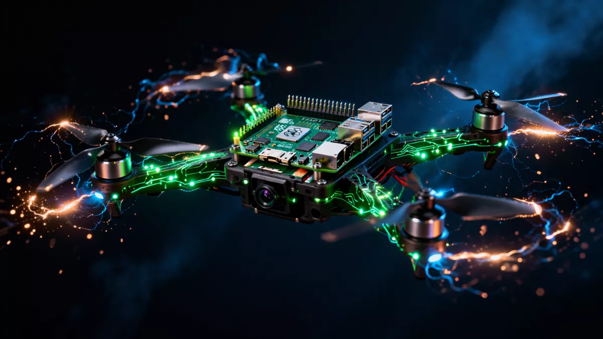
9. Companion Computers: Where Your Smart Code Runs
For anything beyond basic waypoint missions, you need a companion computer. This is an additional onboard computer, separate from the flight controller, that runs your application code.
Common Companion Computers
Raspberry Pi 4 or 5: Affordable, good community support, runs full Linux. Plenty of community examples for drone use. Limited by relatively low performance for computer vision.
NVIDIA Jetson Nano/Orin: The choice for GPU-accelerated inference. If your code does object detection, landing target recognition, or any neural network inference, Jetson hardware is worth the extra cost and weight.
Intel NUC or similar x86 boards: Maximum compute power, but heavy and power-hungry. Used in large research drones.
STM32 or ESP32 microcontrollers: For lightweight edge tasks like sensor interfacing or data logging where a full Linux environment is overkill.
Companion Computer Communication Pattern
The standard pattern is: companion computer connects to flight controller via UART or USB-serial, runs MAVROS or DroneKit, and issues high-level commands. The flight controller handles low-level stabilization and motor control.
Your code on the companion computer should never assume it is the sole authority. The flight controller has its own failsafe logic that can override your commands. Design your code with this in mind: handle failsafe transitions gracefully, listen for mode changes that your code did not initiate, and always have a path to safe landing.
10. Propellers: The Last Hardware Link Your Motor Commands Flow Through
Propellers convert motor rotation into thrust. The relationship between propeller size, pitch, and motor KV determines how efficiently your drone converts electrical power into lift.
Propeller Specifications and Thrust Calculations
A propeller is described as diameter x pitch, for example 5×4.5 (5 inch diameter, 4.5 inch pitch). Pitch is the distance the propeller would theoretically move forward in one rotation in a solid medium. Higher pitch means more air moved per rotation but also more load on the motor.
If you are writing a thrust model for simulation or for calculating maximum payload, you need to know propeller efficiency curves. These are measured in grams of thrust per watt of electrical power, and they vary with RPM and airspeed. Propeller databases like UIUC Propeller Data Site have measured performance data for common propellers that you can feed into your simulation models.
Propeller Direction and Balance
Propellers come in clockwise (CW) and counterclockwise (CCW) versions to match motor rotation direction. An imbalanced or wrong-direction propeller causes vibration that confuses IMU readings and shows up in your flight data as high-frequency noise.
When you are debugging erratic flight behavior and the IMU logs show vibration in the 100-300Hz range, the first thing to check is propeller balance and direction. This is a hardware fix, but identifying it is a code/data analysis task.
11. Putting It All Together: A Programmer’s Mental Model of a Drone
Now let us assemble this into a coherent mental model you can use when writing code.
When you call drone.takeoff(altitude=10) in DroneKit, here is what actually happens:
- DroneKit sends a
COMMAND_LONGMAVLink message with theNAV_TAKEOFFcommand and altitude parameter to the flight controller over serial. - The flight controller receives the command and enters auto-takeoff mode.
- The PID controller starts spinning up motors by increasing the throttle output.
- ESCs receive DSHOT packets from the flight controller with increasing throttle values.
- Motors spin up, spinning propellers that push air downward and generate lift.
- The barometer and GPS measure altitude increase. The IMU measures attitude.
- Sensor fusion feeds corrected altitude data back into the PID controller.
- The drone reaches 10 meters, the flight controller detects the target altitude, and transitions to hover state.
- DroneKit receives a
COMMAND_ACKmessage confirming the command completed. - Your code continues.
That chain, from your Python line to actual flight, crosses serial communication, a real-time OS, sensor fusion, PID control, digital motor protocols, brushless motor physics, and aerodynamics. Every component in that chain is a potential failure point and a potential debugging location.
12. Common Programming Mistakes That Come From Not Understanding Hardware
Let me give you some specific examples of bugs that come from hardware ignorance, because these are the things that will actually cost you time.
Forgetting to arm the motors before sending throttle commands. In ArduPilot, motors are always in an armed or disarmed state as a safety measure. Sending throttle commands to a disarmed drone does nothing. You must explicitly arm via MAVLink before the ESCs will respond.
Sending commands in the wrong reference frame. MAVLink position commands can be in local NED (North-East-Down) frame, body frame (relative to where the drone is pointing), or global GPS frame. Sending a “move forward” command in body frame when the drone is pointing west means the drone moves west, not in the direction your human operator considers “forward.” Always be explicit about frames in your code.
Ignoring EKF (Extended Kalman Filter) health. The EKF is the sensor fusion algorithm in ArduPilot/PX4. If GPS, compass, and barometer data are inconsistent (for example, if the drone launches before GPS gets a good lock), the EKF health flags will indicate a problem. Sending navigation commands when EKF health is bad leads to erratic flight. Your code should check EKF_STATUS_REPORT before starting autonomous missions.
Not handling communication loss failsafes. If your companion computer crashes or your code throws an exception and stops sending heartbeats, the flight controller will trigger a failsafe after a few seconds, typically RTL (Return to Launch) or land. Design your code so that controlled shutdowns always include a graceful handoff back to the flight controller, not a hard crash that stops heartbeats suddenly.
Overwhelming the serial bus with MAVLink requests. Requesting every available telemetry stream at maximum frequency is a common beginner mistake. Serial bandwidth is finite. Requesting GPS at 50Hz, attitude at 50Hz, battery status at 50Hz, and a dozen other streams simultaneously can saturate the link and cause command delivery failures. Be selective about which streams you enable and at what rate.
13. Setting Up Your Development Environment
For anyone who wants to start coding against this hardware immediately, here is the practical path.
Software-in-the-Loop (SITL) Simulation
Before you put code near real hardware, use SITL. Both ArduPilot and PX4 support SITL, which simulates the full flight controller, sensors, and vehicle physics in software. Your code talks to SITL exactly the same way it talks to real hardware.
ArduPilot SITL can be run natively on Linux or in WSL2 on Windows. Pairing it with QGroundControl gives you a full ground station. DroneKit or MAVSDK code written against SITL runs unmodified on real hardware.
Gazebo is the most common physics simulator to pair with PX4 SITL. It renders a full 3D environment, simulates wind, simulates camera sensors, and lets you test computer vision pipelines before flying real hardware.
Logging and Analysis Tools
ArduPilot Blackbox / .bin logs: Every ArduPilot flight generates a detailed binary log of every sensor reading, control output, and mode change at high frequency. Mission Planner and MAVExplorer can open these logs for analysis.
PX4 ULog format: PX4’s logging format is similar. Flight Review at review.px4.io is a web tool that visualizes PX4 logs and automatically identifies common tuning problems.
Blackbox Explorer for Betaflight: If you are working with FPV hardware running Betaflight, Blackbox Explorer decodes the flight controller’s onboard log and shows gyro data, PID outputs, and motor commands on a timeline.
14. Where to Go From Here
If you have read this far, you now have a solid conceptual foundation for drone anatomy from a programmer’s perspective. The logical next steps depend on what you want to build.
If you want to write autonomous navigation code, start with ArduPilot SITL and the DroneKit Python library. Work through basic takeoff-fly-land missions, then add waypoints, then add sensor-based decisions.
If you want to work on computer vision-based flight, get a Raspberry Pi or Jetson, set up MAVROS, and start with marker-based landing. It is a tractable first project that forces you to understand coordinate frames, camera calibration, and closed-loop visual control all at once.
If you want to work on firmware-level code, PX4 is more approachable than ArduPilot for custom module development. Their developer documentation is excellent and the uORB message bus makes adding custom sensor drivers relatively clean.
If you want to go deep on hardware interfacing, buy a Betaflight F4 or F7 flight controller, a cheap 5-inch quadcopter kit, and flash it yourself. Configuring ESC protocols, setting up telemetry, and tuning PIDs on real hardware teaches you things no simulator can replicate.
Conclusion
Drone anatomy for programmers explained properly is not about memorizing part names. It is about building a mental model of a complex embedded system so that every line of code you write is grounded in the physical reality it controls.
You now know that a motor’s KV rating affects your PID tuning, that ESC protocol choice determines your control loop latency, that flight controller firmware defines your programming interface, that GPS latency needs to be compensated in fast autonomous code, that MAVLink is the language your software speaks to autopilots, and that sensor fusion health determines whether your navigation commands will work at all.
Every one of those connections between software concepts and physical hardware will save you debugging time and make your code more reliable. The drone is not a black box anymore. It is a system you understand, and systems you understand are systems you can build on confidently.
Quick Reference: Key Terms for Drone Programmers
| Term | What It Means for Your Code |
|---|---|
| KV Rating | Affects thrust model and PID tuning sensitivity |
| DSHOT | Digital ESC protocol with RPM telemetry feedback |
| PID | Control algorithm you configure and sometimes implement |
| EKF | Sensor fusion health check before autonomous flight |
| MAVLink | The protocol your drone communication code speaks |
| Guided/Offboard Mode | The flight mode that allows external code control |
| SITL | Software simulation environment for safe code testing |
| RTK GPS | Centimeter-accurate positioning for precision applications |
| SBUS/CRSF | RC receiver protocols for human override systems |
| mAh Consumed | Better battery state metric than voltage for flight planning |
This article covers drone hardware and software concepts for educational purposes. Always follow local regulations for drone operation and never fly autonomous drones without proper safety measures in place.
If you are completely new to drones altogether, start with this guide on Types of Drones Explained: Your Complete Beginner’s Guide for 2026 first, then come back here it will make everything below click faster.
Mr. Raj Kumar is a highly experienced Technical Content Engineer with 7 years of dedicated expertise in the intricate field of embedded systems. At Embedded Prep, Raj is at the forefront of creating and curating high-quality technical content designed to educate and empower aspiring and seasoned professionals in the embedded domain.
Throughout his career, Raj has honed a unique skill set that bridges the gap between deep technical understanding and effective communication. His work encompasses a wide range of educational materials, including in-depth tutorials, practical guides, course modules, and insightful articles focused on embedded hardware and software solutions. He possesses a strong grasp of embedded architectures, microcontrollers, real-time operating systems (RTOS), firmware development, and various communication protocols relevant to the embedded industry.
Raj is adept at collaborating closely with subject matter experts, engineers, and instructional designers to ensure the accuracy, completeness, and pedagogical effectiveness of the content. His meticulous attention to detail and commitment to clarity are instrumental in transforming complex embedded concepts into easily digestible and engaging learning experiences. At Embedded Prep, he plays a crucial role in building a robust knowledge base that helps learners master the complexities of embedded technologies.