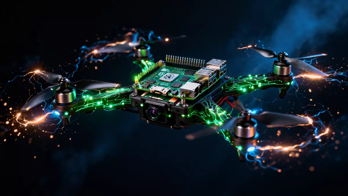
Learn how to build a Raspberry Pi powered drone from scratch with full Python code, wiring diagrams, PID tuning, and a step-by-step beginner guide.
Here’s the honest truth: building a Raspberry Pi powered drone is not the cheapest or easiest way to get something flying. You can buy a ready-to-fly drone for $50 on Amazon. So why would you spend weeks soldering wires and debugging Python code instead?
Because what you actually end up with is completely different. A commercial drone is a sealed box you point at the sky. A Raspberry Pi drone project is a computer you built that happens to fly. Once you’ve built one, you understand every single thing happening between the moment you arm it and the moment it lands. You can add a camera, hook it up to computer vision, program autonomous waypoints, or attach any sensor that communicates over I2C or SPI.
Researchers use Raspberry Pi drones for mapping. Engineering students use them for autonomous flight experiments. Hobbyists build them because flying something you wrote from scratch hits differently than anything you can buy off a shelf.
This guide is written for someone who has maybe played with a Raspberry Pi before, knows basic Python, and can follow instructions carefully. You don’t need an electrical engineering degree. You do need patience.
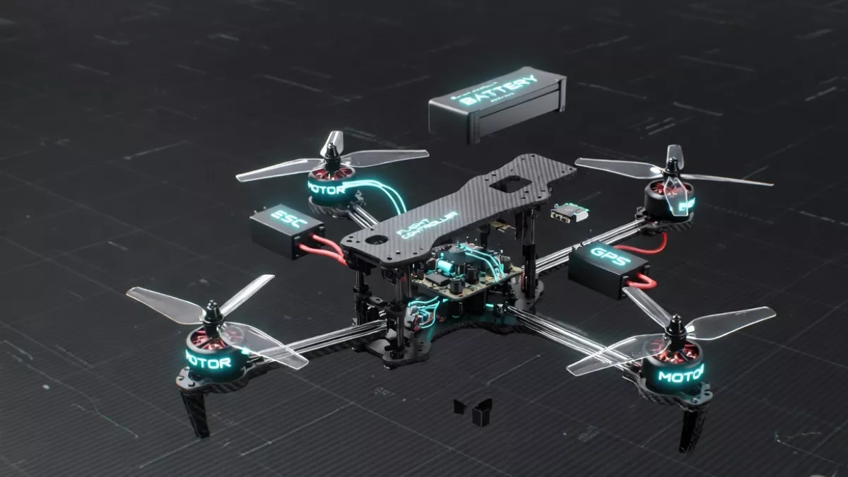
What you’ll have at the end: A fully functional quadcopter with a Raspberry Pi 4 as the flight controller brain, running a custom Python PID control loop, controllable via radio transmitter, with real-time telemetry. Total cost: roughly $180–$250 USD depending on where you source parts.
Build a Raspberry Pi Powered Drone
1. Complete Parts List and Budget Breakdown
Before you buy anything, read this section twice. Parts compatibility is the single biggest source of frustration in DIY drone building. Everything here has been chosen to work together without modification.
| Component | Recommended Model | Approx. Cost | Notes |
|---|---|---|---|
| Flight Computer | Raspberry Pi 4 (2GB or 4GB) | $35–$55 | Pi Zero 2W also works for weight savings |
| Frame | F450 Quadcopter Frame | $12–$18 | 450mm wheelbase, includes PCB power distribution board |
| Brushless Motors (x4) | EMAX RS2205 2300KV | $10–$14 each | Match KV rating to battery voltage |
| ESCs (x4) | LittleBee 30A BLHeli-S | $8–$12 each | Must support PWM or DSHOT protocol |
| Propellers | 5045 Tri-blade (4 pairs) | $8 total | Buy extras — they break |
| Battery | 3S 2200mAh 40C LiPo | $18–$25 | 3S = 11.1V nominal |
| IMU | MPU-6050 breakout board | $3–$6 | 6-DOF, I2C interface |
| Barometer | BMP280 | $2–$4 | Altitude hold capability |
| RC Receiver | FlySky FS-iA6B | $15–$20 | 6-channel, iBUS protocol |
| RC Transmitter | FlySky FS-i6X | $45–$55 | Pairs with FS-iA6B receiver |
| BEC / UBEC | 5V 3A UBEC | $5–$8 | Powers Pi from LiPo cleanly |
| LiPo Charger | iMAX B6AC | $25–$35 | Balance charging is non-negotiable for safety |
| Misc | Wires, heat shrink, standoffs, zip ties | $10–$15 | JST connectors are your best friend |
⚠ Safety First: LiPo batteries are not forgiving. Always use a proper balance charger, never charge unattended, and store them in a LiPo-safe bag. A puffed or punctured LiPo can catch fire within seconds. This is not fear-mongering — it’s the one thing you take seriously throughout this entire build.
Tools You’ll Need
- Soldering iron (60W minimum, adjustable temperature preferred)
- Rosin-core solder (63/37 tin/lead or lead-free)
- Digital multimeter
- Hex screwdriver set (M2, M3)
- Wire strippers and crimping tool
- Hot glue gun for vibration management
- Laptop or desktop with SSH access
- MicroSD card (16GB+ Class 10)
2. Assembling the Drone Frame
The F450 frame is the gold standard entry-level quadcopter frame for a reason. The four arms bolt onto a central PCB that doubles as your power distribution board, which means you’re soldering motors to the frame itself rather than running eight separate power wires everywhere. Clean, simple, effective.
Step 1 — Identify Your Arms
The F450 uses two red arms (front) and two white arms (rear). This color coding is how you’ll know which way your drone is pointing in the air. Front-left and front-right go red. Rear-left and rear-right go white. Bolt them to the bottom PCB plate first using M3 screws — don’t fully tighten yet.
Step 2 — Solder Power Pads
The F450’s bottom PCB has labeled solder pads. Tin the pads with your iron before attaching wires. You’ll solder your ESC power leads (red=positive, black=negative) to the corresponding pads on each arm. The main battery leads connect to the large pads in the center. Use 14AWG wire for the battery connector — anything thinner will heat up under current load.
Step 3 — Mount Motors to Arms
Each EMAX RS2205 motor bolts to the end of its arm using M3 screws through the motor mount. Thread the three motor phase wires down through the arm channel. Don’t worry about which order you connect them yet — motor direction is determined by which two of the three phase wires you swap, and you’ll sort that out during testing.
Step 4 — Mount Top Plate and Standoffs
Once the bottom assembly is solid, add M3 brass standoffs (35mm height recommended) to mount the top plate. This is where your Raspberry Pi, IMU, and receiver will live. Use a tiny drop of Loctite Blue on each threaded connection — vibration will loosen screws during flight.
Motor Layout and Spin Direction
This is critical. Quadcopters need specific motor spin directions to maintain yaw stability:
         FRONT
  M1 (CCW) --- M2 (CW)
      \             /
       \           /
        [  BODY  ]
       /           \
      /             \
  M4 (CW)  --- M3 (CCW)
         REAR

M1 = Front-Left  = Counter-Clockwise (CCW)
M2 = Front-Right = Clockwise (CW)
M3 = Rear-Right  = Counter-Clockwise (CCW)
M4 = Rear-Left   = Clockwise (CW)

Rule: Diagonal motors spin the SAME direction.
      Adjacent motors spin OPPOSITE directions.
3. Motors, ESCs, and Propellers Explained
If you want your DIY Raspberry Pi drone to actually lift off the ground, you need to understand the relationship between your motor’s KV rating, your battery voltage, and your propeller size.
Understanding KV Ratings
KV is RPM per volt. A 2300KV motor on a 3S LiPo (12.6V fully charged) spins at approximately 29,000 RPM unloaded. Under load with a 5-inch prop, you’re looking at 18,000–22,000 RPM. The general rule: higher KV = smaller props, more speed, less torque. For our F450 build, 2300KV motors with 5045 props gives you 600–800g of thrust per motor — more than enough to lift our ~600g finished build.
Connecting ESCs
Each ESC has three connections:
- Power input (thick red/black wires): Soldered to the F450 power distribution pads
- Motor output (three phase wires): Connected to your brushless motor
- Signal wire (thin 3-pin servo connector): Goes to your Raspberry Pi GPIO
The BLHeli-S ESCs support standard 50Hz PWM signals from 1000–2000 microseconds pulse width. 1000μs = motors off. 2000μs = full throttle. Your Python code outputs these signals through the Pi’s GPIO pins using the pigpio library.
ESC Calibration
- With props OFF and battery disconnected, connect the ESC signal wire to the Pi
- Power on the ESC while sending a 2000μs (full throttle) signal
- Wait for the confirmation beeps (usually 2–3 beeps)
- Immediately drop to 1000μs (zero throttle)
- Wait for the arm beeps
- Repeat for all four ESCs
⚠ Always remove propellers during ESC calibration and any software testing. An accidentally armed motor with propellers on is how people lose fingers. Every experienced builder has a story. Learn from theirs, not yours.
4. Setting Up Your Raspberry Pi for Flight Control
Your Raspberry Pi is about to become the brain of a flying machine, so the OS setup matters more than on a normal Pi project. We need real-time performance, minimal latency, and reliable GPIO control.
OS Installation
Download Raspberry Pi OS Lite (64-bit) from the official Raspberry Pi website. We’re using Lite because we don’t need a desktop environment, and every megabyte of unused software is latency we don’t need. Flash it to your MicroSD using Raspberry Pi Imager.
Before your first boot, create an empty file called ssh in the boot partition to enable SSH, and add your WiFi credentials:
# wpa_supplicant.conf
country=US
ctrl_interface=DIR=/var/run/wpa_supplicant GROUP=netdev
update_config=1

network={
    ssid="YourNetworkName"
    psk="YourPassword"
    key_mgmt=WPA-PSK
}
System Configuration
SSH into your Pi and run this full setup sequence:
sudo apt update && sudo apt upgrade -y

# Install required Python libraries
sudo apt install -y python3-pip python3-dev i2c-tools git

# Install pigpio — critical for precise GPIO timing
sudo apt install -y pigpio python3-pigpio
sudo systemctl enable pigpiod
sudo systemctl start pigpiod

# Install Python dependencies
pip3 install smbus2 pyserial numpy RPi.GPIO

# Enable I2C and SPI
sudo raspi-config nonint do_i2c 0
sudo raspi-config nonint do_spi 0

# Reduce GPU memory split
echo "gpu_mem=16" | sudo tee -a /boot/config.txt

# Enable UART for RC receiver
echo "enable_uart=1" | sudo tee -a /boot/config.txt
echo "dtoverlay=disable-bt" | sudo tee -a /boot/config.txt

sudo reboot
Real-Time Performance Tuning
Linux is not a real-time OS by default. The kernel scheduler can interrupt your control loop at inconvenient moments. For a flight controller, even a 50ms hiccup can cause instability:
# Set CPU governor to performance mode
echo performance | sudo tee /sys/devices/system/cpu/cpu*/cpufreq/scaling_governor

# Disable unnecessary services
sudo systemctl disable bluetooth
sudo systemctl disable avahi-daemon
sudo systemctl disable triggerhappy
5. Full Wiring Guide with GPIO Pinout
This is the section where most beginners make irreversible mistakes. Take your time, use a multimeter to verify every connection before applying power, and label your wires.
Raspberry Pi 4 GPIO Pinout — Drone Build
==========================================

POWER RAILS
  Pin 2  (5V)      → UBEC 5V output (+)
  Pin 6  (GND)     → UBEC GND / Common Ground

ESC SIGNAL WIRES (BCM numbering)
  GPIO 18 (Pin 12) → ESC1 Signal  (Front-Left  Motor M1)
  GPIO 23 (Pin 16) → ESC2 Signal  (Front-Right Motor M2)
  GPIO 24 (Pin 18) → ESC3 Signal  (Rear-Right  Motor M3)
  GPIO 25 (Pin 22) → ESC4 Signal  (Rear-Left   Motor M4)
  GND              → ESC Signal Ground (connect all 4)

MPU-6050 IMU (I2C)
  Pin 3  (SDA1)    → MPU-6050 SDA
  Pin 5  (SCL1)    → MPU-6050 SCL
  Pin 1  (3.3V)    → MPU-6050 VCC
  Pin 9  (GND)     → MPU-6050 GND

BMP280 BAROMETER (same I2C bus, address 0x76)
  Pin 3  (SDA1)    → BMP280 SDA
  Pin 5  (SCL1)    → BMP280 SCL
  Pin 17 (3.3V)    → BMP280 VCC

RC RECEIVER FlySky FS-iA6B (iBUS via UART)
  Pin 10 (UART RX) → Receiver iBUS output
  Pin 6  (GND)     → Receiver GND
  5V               → Receiver VCC (from UBEC)
⚠ Critical Wiring Warning: Do NOT connect the ESC’s red 5V wire to the Pi’s 5V rail. This creates a ground loop and can destroy your Pi. Tape off the red wire on every ESC signal connector — only signal (white/yellow) and ground (black) connect to the Pi.
Power Architecture
- High-power domain: LiPo → Power Distribution Board → ESCs → Motors. Carries up to 30A and produces electrical noise that corrupts sensor readings.
- Low-power domain: UBEC takes LiPo voltage in, outputs regulated 5V → Raspberry Pi + sensors. The UBEC isolates the Pi from the noisy motor circuit.
Always connect your main battery last and disconnect it first. Every time. Without exception.
6. IMU and Sensor Integration
The MPU-6050 is your drone’s inner ear. It contains a 3-axis accelerometer and 3-axis gyroscope. The gyroscope measures how fast the drone rotates around each axis (roll, pitch, yaw). The accelerometer measures linear acceleration including gravity. Your PID controller uses these readings hundreds of times per second.
Verify I2C Connection First
# Scan I2C bus — run this before writing any code
sudo i2cdetect -y 1

# You should see:
# 0x68 = MPU-6050
# 0x76 = BMP280
mpu6050.py — IMU Driver
import smbus2
import time
import math

class MPU6050:
    ADDR         = 0x68
    PWR_MGMT_1   = 0x6B
    ACCEL_XOUT_H = 0x3B
    GYRO_XOUT_H  = 0x43
    GYRO_CONFIG  = 0x1B
    ACCEL_CONFIG = 0x1C

    def __init__(self):
        self.bus = smbus2.SMBus(1)
        # Wake up the MPU-6050 (exits sleep mode)
        self.bus.write_byte_data(self.ADDR, self.PWR_MGMT_1, 0x00)
        time.sleep(0.1)
        # Set gyro full-scale range to +-500 deg/s
        self.bus.write_byte_data(self.ADDR, self.GYRO_CONFIG, 0x08)
        # Set accel full-scale range to +-4g
        self.bus.write_byte_data(self.ADDR, self.ACCEL_CONFIG, 0x08)
        self.gyro_offset = {'x': 0.0, 'y': 0.0, 'z': 0.0}

    def _read_raw_data(self, reg):
        high  = self.bus.read_byte_data(self.ADDR, reg)
        low   = self.bus.read_byte_data(self.ADDR, reg + 1)
        value = (high << 8) | low
        if value > 32767:
            value -= 65536
        return value

    def get_gyro(self):
        scale = 65.5  # LSB per deg/s for +-500 range
        return {
            'x': (self._read_raw_data(self.GYRO_XOUT_H)     / scale) - self.gyro_offset['x'],
            'y': (self._read_raw_data(self.GYRO_XOUT_H + 2) / scale) - self.gyro_offset['y'],
            'z': (self._read_raw_data(self.GYRO_XOUT_H + 4) / scale) - self.gyro_offset['z'],
        }

    def get_accel(self):
        scale = 8192.0  # LSB per g for +-4g range
        return {
            'x': self._read_raw_data(self.ACCEL_XOUT_H)     / scale,
            'y': self._read_raw_data(self.ACCEL_XOUT_H + 2) / scale,
            'z': self._read_raw_data(self.ACCEL_XOUT_H + 4) / scale,
        }

    def get_angle(self):
        a     = self.get_accel()
        roll  = math.atan2(a['y'], a['z']) * (180 / math.pi)
        pitch = math.atan2(-a['x'], math.sqrt(a['y']**2 + a['z']**2)) * (180 / math.pi)
        return roll, pitch

    def calibrate_gyro(self, samples=2000):
        print("Calibrating gyro... keep drone perfectly still")
        sx = sy = sz = 0.0
        for _ in range(samples):
            g = self.get_gyro()
            sx += g['x']
            sy += g['y']
            sz += g['z']
            time.sleep(0.002)
        self.gyro_offset = {
            'x': sx / samples,
            'y': sy / samples,
            'z': sz / samples
        }
        print(f"Gyro offsets: {self.gyro_offset}")
7. Complete Python Flight Controller Code
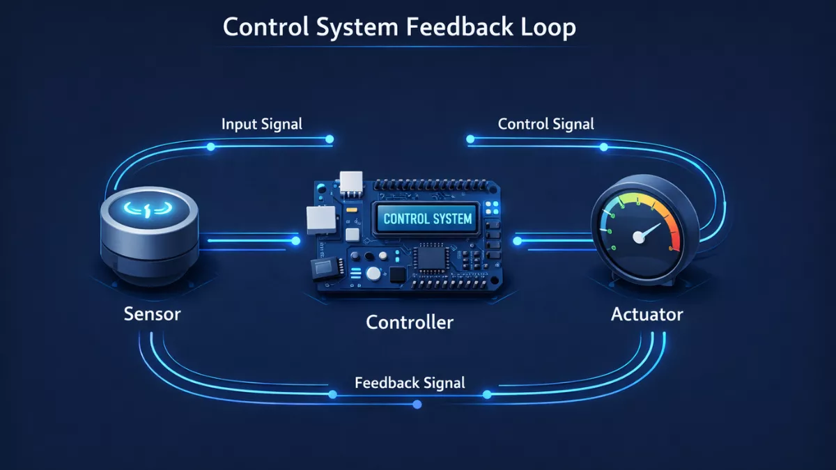
This is the core of your Raspberry Pi flight controller build. The loop runs at 100Hz: read IMU → compute orientation → read RC inputs → calculate PID corrections → output PWM to ESCs. Every iteration should complete in under 10ms.
complementary_filter.py
class ComplementaryFilter:
    def __init__(self, alpha=0.98):
        # alpha: weight for gyro (trust gyro 98%, accel 2%)
        # Gyro is accurate short-term but drifts over time
        # Accel is noisy but drift-free — blend both
        self.alpha = alpha
        self.roll  = 0.0
        self.pitch = 0.0

    def update(self, gyro, accel_angle, dt):
        roll_accel, pitch_accel = accel_angle
        self.roll  = self.alpha * (self.roll  + gyro['x'] * dt) + (1 - self.alpha) * roll_accel
        self.pitch = self.alpha * (self.pitch + gyro['y'] * dt) + (1 - self.alpha) * pitch_accel
        return self.roll, self.pitch
pid.py — Reusable PID Controller
class PID:
    def __init__(self, kp, ki, kd, setpoint=0.0, output_limits=(-400, 400)):
        self.kp = kp
        self.ki = ki
        self.kd = kd
        self.setpoint      = setpoint
        self.output_limits = output_limits
        self._integral     = 0.0
        self._prev_error   = 0.0

    def compute(self, measured_value, dt):
        error = self.setpoint - measured_value

        # Proportional term
        p_term = self.kp * error

        # Integral with anti-windup clamp
        self._integral = max(-50, min(50, self._integral + error * dt))
        i_term = self.ki * self._integral

        # Derivative on measurement (avoids derivative kick on setpoint change)
        d_term = self.kd * (error - self._prev_error) / dt if dt > 0 else 0
        self._prev_error = error

        low, high = self.output_limits
        return max(low, min(high, p_term + i_term + d_term))

    def reset(self):
        self._integral   = 0.0
        self._prev_error = 0.0
rc_receiver.py — FlySky iBUS Reader
import serial
import threading

class IBUSReceiver:
    IBUS_LENGTH = 32
    IBUS_HEADER = 0x20

    def __init__(self, port='/dev/serial0', baud=115200):
        self.ser      = serial.Serial(port, baud, timeout=0.1)
        self.channels = [1500] * 6
        self.channels[2] = 1000   # Throttle defaults to zero
        self._lock   = threading.Lock()
        self._thread = threading.Thread(target=self._read_loop, daemon=True)
        self._thread.start()

    def _read_loop(self):
        while True:
            try:
                data = self.ser.read(1)
                if not data:
                    continue
                if data[0] == self.IBUS_HEADER:
                    packet = data + self.ser.read(self.IBUS_LENGTH - 1)
                    if len(packet) == self.IBUS_LENGTH:
                        self._parse(packet)
            except Exception:
                pass

    def _parse(self, packet):
        # Validate checksum
        checksum = 0xFFFF
        for i in range(self.IBUS_LENGTH - 2):
            checksum -= packet[i]
        if checksum != (packet[30] | (packet[31] << 8)):
            return
        with self._lock:
            for i in range(6):
                offset = 2 + i * 2
                self.channels[i] = packet[offset] | (packet[offset + 1] << 8)

    def get_channels(self):
        with self._lock:
            return list(self.channels)
flight_controller.py — Main Entry Point
import pigpio
import time
import os
from mpu6050 import MPU6050
from complementary_filter import ComplementaryFilter
from pid import PID
from rc_receiver import IBUSReceiver

# ── CONFIGURATION ────────────────────────────────────────────────────
MOTOR_PINS = {'m1': 18, 'm2': 23, 'm3': 24, 'm4': 25}
MOTOR_MIN  = 1000   # microseconds (disarmed)
MOTOR_MAX  = 2000   # microseconds (full throttle)
LOOP_HZ    = 100    # target control loop frequency

# PID gains — conservative starting values, tune after first hover
ROLL_PID  = PID(kp=1.2, ki=0.02, kd=0.15)
PITCH_PID = PID(kp=1.2, ki=0.02, kd=0.15)
YAW_PID   = PID(kp=2.0, ki=0.0,  kd=0.0)

# ── SETUP ────────────────────────────────────────────────────────────
def setup():
    os.nice(-10)   # elevate process priority
    pi = pigpio.pi()
    if not pi.connected:
        raise RuntimeError("pigpiod not running. Run: sudo systemctl start pigpiod")
    for name, pin in MOTOR_PINS.items():
        pi.set_servo_pulsewidth(pin, MOTOR_MIN)
    print("Motors initialized at DISARMED state")
    time.sleep(2)  # give ESCs time to register min signal
    imu = MPU6050()
    imu.calibrate_gyro()
    return pi, imu, ComplementaryFilter(0.98), IBUSReceiver()

# ── MOTOR MIXING ─────────────────────────────────────────────────────
def motor_mix(throttle, roll_corr, pitch_corr, yaw_corr):
    """
    X-frame quadcopter motor mixing.
    Diagonal motors spin same direction; adjacent motors spin opposite.
    """
    def clamp(v):
        return int(max(MOTOR_MIN, min(MOTOR_MAX, v)))
    return {
        'm1': clamp(throttle - roll_corr + pitch_corr - yaw_corr),  # Front-Left  CCW
        'm2': clamp(throttle + roll_corr + pitch_corr + yaw_corr),  # Front-Right CW
        'm3': clamp(throttle + roll_corr - pitch_corr - yaw_corr),  # Rear-Right  CCW
        'm4': clamp(throttle - roll_corr - pitch_corr + yaw_corr),  # Rear-Left   CW
    }

# ── MAIN CONTROL LOOP ────────────────────────────────────────────────
def run():
    pi, imu, cf, rc = setup()
    dt_target = 1.0 / LOOP_HZ
    armed  = False
    t_prev = time.time()
    print("Flight controller ready. Arm: throttle to minimum.")

    try:
        while True:
            t_now = time.time()
            dt    = t_now - t_prev
            t_prev = t_now

            # Read sensors
            gyro        = imu.get_gyro()
            roll, pitch = cf.update(gyro, imu.get_angle(), dt)

            # Read RC channels
            # Ch mapping: 0=Roll, 1=Pitch, 2=Throttle, 3=Yaw
            ch = rc.get_channels()

            # Arming logic
            if ch[2] < 1050:
                armed = True
            if ch[2] < 1050 and ch[3] < 1050:
                armed = False
                ROLL_PID.reset()
                PITCH_PID.reset()
                YAW_PID.reset()

            if not armed:
                for _, pin in MOTOR_PINS.items():
                    pi.set_servo_pulsewidth(pin, MOTOR_MIN)
                time.sleep(dt_target)
                continue

            # Convert RC to setpoints
            ROLL_PID.setpoint  = (ch[0] - 1500) * 0.03   # +-15 degree range
            PITCH_PID.setpoint = (ch[1] - 1500) * 0.03
            YAW_PID.setpoint   = (ch[3] - 1500) * 0.2    # degrees/sec

            # Compute PID corrections
            roll_corr  = ROLL_PID.compute(roll,      dt)
            pitch_corr = PITCH_PID.compute(pitch,    dt)
            yaw_corr   = YAW_PID.compute(gyro['z'], dt)

            # Mix and output to motors
            motors = motor_mix(ch[2], roll_corr, pitch_corr, yaw_corr)
            for name, pin in MOTOR_PINS.items():
                pi.set_servo_pulsewidth(pin, motors[name])

            # Maintain loop timing
            elapsed = time.time() - t_now
            if dt_target - elapsed > 0:
                time.sleep(dt_target - elapsed)

    except KeyboardInterrupt:
        print("\nShutting down safely...")
    finally:
        # Emergency stop — always runs even on crash
        for _, pin in MOTOR_PINS.items():
            pi.set_servo_pulsewidth(pin, 0)
        pi.stop()
        print("Motors stopped. GPIO released.")

if __name__ == '__main__':
    run()
Run command:
sudo python3 flight_controller.py— sudo is required for pigpio hardware access and the os.nice() priority elevation.
8. PID Tuning for Stable Flight
PID tuning is where your Raspberry Pi drone build goes from “terrifying bouncing machine” to something that actually hovers. There’s no shortcut — every airframe behaves differently depending on motor placement, prop size, battery weight, and center of gravity.
Understanding the Three Terms
Kp (Proportional) is the main correction force. If the drone is tilted 10 degrees and Kp is 1.2, it applies 12 units of correction. Too low and the drone is sluggish. Too high and it overshoots and starts oscillating — a drone with excessive P gain looks like it’s bouncing on a spring in mid-air.
Ki (Integral) corrects for sustained errors — things like a center-of-gravity offset or unequal motor outputs that cause slow drift. Keep Ki very low. Integral windup is a real problem: if the drone sits on the ground while armed, the I term winds up to a huge number and causes a violent snap on takeoff. The anti-windup clamp in our code prevents this.
Kd (Derivative) dampens oscillations caused by high Kp. Think of it as a shock absorber. Too much D and the drone responds to sensor noise rather than actual movement — this is called “D term buzz” and you’ll hear it as a high-pitched hum in the motors.
Tuning Sequence
- Start with Ki=0, Kd=0. Increase Kp until oscillations begin, then back off 20%
- Add Kd gradually until oscillations are dampened without introducing buzz
- Add Ki last, in tiny increments, to eliminate long-term drift
- Tune roll and pitch independently — they can have different values if your frame is not perfectly symmetrical
- Only tune yaw after roll/pitch are solid
Pro Tip: Tune over a soft surface — grass, foam mats, or even a pile of pillows under your test area. Hover-tune at one inch altitude so crashes are cheap. Your first 20 tuning flights will involve unexpected behavior. Plan for it.
9. Adding RC Control and Telemetry
Binding the FlySky System
- Power off everything
- On the FS-iA6B receiver, insert the bind plug into the BAT port
- Power up the receiver — LED will flash rapidly
- On the FS-i6X transmitter, hold BIND KEY while powering on
- Wait for “Bind success” message on transmitter screen
- Remove bind plug from receiver
- Power cycle both — solid LED on receiver means bound and working
Enable iBUS Output
- On transmitter: SYSTEM → RX Setup → Serial receiver type → iBUS
- The receiver reconfigures automatically after re-binding
- Connect the iBUS port (not the PWM ports) to your Pi’s UART RX pin
Simple WiFi Telemetry Server
Install the library first: pip3 install websockets
import asyncio
import websockets
import json
import threading

telemetry_data = {
    'roll': 0.0, 'pitch': 0.0, 'throttle': 0,
    'm1': 0, 'm2': 0, 'm3': 0, 'm4': 0,
    'loop_hz': 0, 'armed': False
}

async def handler(websocket, path):
    while True:
        await websocket.send(json.dumps(telemetry_data))
        await asyncio.sleep(0.1)  # 10Hz telemetry refresh

def start_telemetry_server():
    loop = asyncio.new_event_loop()
    asyncio.set_event_loop(loop)
    start_server = websockets.serve(handler, "0.0.0.0", 8765)
    loop.run_until_complete(start_server)
    loop.run_forever()

# Add to your flight controller startup:
# t = threading.Thread(target=start_telemetry_server, daemon=True)
# t.start()
# Connect browser to: ws://[Pi IP address]:8765
10. Pre-Flight Checklist and Safety
The difference between a successful first flight and an expensive rebuild comes down to how carefully you work through this list every single time.
Physical Inspection
- All motor screws tight — zero play when you wiggle each motor
- Props seated correctly, bolted down, correct spin direction per motor
- Frame arms show no cracks or stress marks
- All wires routed completely away from propeller arc
- LiPo cell voltage: all cells within 0.1V of each other, total above 11.1V for 3S
- LiPo shows no puffing, heat, or physical damage
- Pi boots cleanly via SSH with no filesystem errors
Software Checks
systemctl status pigpiod— daemon must show active/runningsudo i2cdetect -y 1— 0x68 must appear for IMU- RC receiver getting valid channels — print them and move sticks
- Motor test with props OFF: each motor spins correct direction
- Failsafe confirmed: RC signal loss stops all motors within 0.5 seconds
Legal Requirements
In India, the DGCA (Directorate General of Civil Aviation) requires drone pilots to register aircraft and obtain a Remote Pilot Certificate for drones above 250g. Our build exceeds 250g. Check current rules at digitalsky.dgca.gov.in before flying outdoors. Never fly near airports, above 60m without authorization, or over populated areas.
⚠ First Flight Location: Choose a large open field well away from people, roads, and overhead wires. Bring a fire extinguisher or bucket of sand. Keep the drone under 3 feet altitude for your first 10 flights. Low crashes are repairable. High crashes are not.
11. Troubleshooting Common Problems
Drone Flips Immediately on Takeoff
The most common first-flight problem. Three causes:
- Wrong motor spin direction: Swap any two of the three phase wires on the offending motor. A CW motor running CCW causes an instant flip toward that corner.
- Props on wrong motors: CW props have a right-hand blade twist. CCW props twist left. They’re not interchangeable. Most packs are labeled R (CW) and N (CCW).
- Motor mix polarity wrong: Double-check your motor_mix() function matches the actual physical position of each motor.
Motors Beeping Constantly
ESC arming beeps are normal (3 descending tones = armed). Constant rapid beeping means the ESC isn’t receiving a valid signal. Check that pigpiod is running, your GPIO pin numbers match physical connections, and common ground is established between Pi and ESC signal wires.
IMU Not Detected on I2C
Run sudo i2cdetect -y 1. If 0x68 doesn’t appear: check 3.3V power to the MPU-6050, check that SDA and SCL aren’t swapped, confirm I2C is enabled in raspi-config. Cheap MPU-6050 boards sometimes have AD0 floating — add a 4.7kΩ pull-down resistor to ground to force address 0x68.
RC Channels Not Reading
Confirm iBUS is enabled in transmitter settings (not PPM). Then verify /dev/serial0 exists and UART is enabled in /boot/config.txt with Bluetooth disabled. Quick debug:
from rc_receiver import IBUSReceiver
import time

rc = IBUSReceiver()
while True:
    print(rc.get_channels())
    time.sleep(0.1)
Drone Oscillates in Hover
Classic Kp-too-high symptom. Drop Kp by 20% on both roll and pitch. Slow, lazy oscillations = Kp too low. Fast, high-frequency shaking = D term picking up sensor noise. Reduce Kd or add a low-pass filter to your gyro readings.
Control Loop Running Under 80Hz
Check CPU usage with htop. Common culprits: WiFi scanning, system logging, background OS updates. Disable unnecessary services. Also set I2C clock to 400kHz in /boot/config.txt: dtparam=i2c_arm_baudrate=400000
12. Frequently Asked Questions
Can I use a Raspberry Pi Zero 2W instead of the Pi 4?
Yes, and it’s a great choice for weight savings. The Zero 2W is about 10g vs the Pi 4’s 46g — significant on a small frame. The CPU handles a 100Hz control loop just fine. Main tradeoff: fewer GPIO pins and only one hardware UART. Setup steps are identical.
Is this safer to fly indoors or outdoors?
Outdoors, without question, for your first flights. Indoors means confined space, turbulence from walls, and nowhere to run if something goes wrong. Start in a large open outdoor field, keep altitude low, and stay well clear of people.
How do I add GPS for autonomous flight?
Connect a u-blox NEO-M8N GPS module to your second UART port (/dev/serial1 or via USB adapter). Parse NMEA sentences directly or use the gpsd library. For full autonomous navigation, look into ROS (Robot Operating System) on the Pi — it has mature navigation stacks built for exactly this use case.
What flight time can I expect?
With the 2200mAh 3S battery, expect roughly 8–12 minutes of actual flight time. Highly dependent on how aggressively you fly, total build weight, and ambient temperature (LiPo capacity drops in cold weather). Add a low-voltage beeper to your LiPo balance connector to know when to land.
Why not just use ArduPilot or Betaflight instead of custom code?
You can — ArduPilot Linux runs well on the Pi. But writing your own flight controller teaches you things that using ArduPilot never will: PID control, sensor fusion, real-time constraints, motor mixing. Once you’ve built one from scratch, you’ll actually understand what ArduPilot is doing under the hood, which matters when you want to debug unexpected behavior or add custom autonomous logic.
Can I add a camera to this build?
Yes. The Raspberry Pi Camera Module 3 connects directly to the CSI port. For FPV, use a dedicated analog FPV camera with a video transmitter — the Pi camera has too much latency for real-time FPV. For vision processing, recording, or machine learning, the Pi 4 handles 1080p30 comfortably.
What if I accidentally over-discharge my LiPo?
A LiPo below 3.0V per cell (9.0V total for 3S) is over-discharged and likely permanently damaged. A puffed LiPo must be disposed of at a battery recycling facility — never in regular trash. Always use a low-voltage alarm that beeps when cells drop below 3.5V per cell during flight.
Final Thoughts
Building a Raspberry Pi powered drone from scratch is genuinely one of the most satisfying things you can build as an electronics hobbyist or engineer. Every part you’ve chosen, every wire you’ve soldered, every line of Python you’ve written is doing real physics work in real time, keeping your machine in the air. That first hover — even if it’s shaky and lasts three seconds before you land nervously — is unforgettable.
The code in this guide is production-ready for a first build, but treat it as a living codebase. Add sensor filtering. Implement proper failsafes. Experiment with altitude hold using the BMP280. Add GPS waypoint navigation. The Raspberry Pi gives you the compute headroom to keep building long after your first successful flight. That’s the whole point.
Once you’ve got your quadcopter flying confidently, the natural next step for a lot of builders is learning to program it. Not just configure Betaflight, but actually write code that controls autonomous missions, waypoints, and failsafe logic. If that interests you, check out this detailed guide on how to learn drone programming from scratch in 2026 it covers the full stack from MAVLink basics to Python DroneKit missions.
Mr. Raj Kumar is a highly experienced Technical Content Engineer with 7 years of dedicated expertise in the intricate field of embedded systems. At Embedded Prep, Raj is at the forefront of creating and curating high-quality technical content designed to educate and empower aspiring and seasoned professionals in the embedded domain.
Throughout his career, Raj has honed a unique skill set that bridges the gap between deep technical understanding and effective communication. His work encompasses a wide range of educational materials, including in-depth tutorials, practical guides, course modules, and insightful articles focused on embedded hardware and software solutions. He possesses a strong grasp of embedded architectures, microcontrollers, real-time operating systems (RTOS), firmware development, and various communication protocols relevant to the embedded industry.
Raj is adept at collaborating closely with subject matter experts, engineers, and instructional designers to ensure the accuracy, completeness, and pedagogical effectiveness of the content. His meticulous attention to detail and commitment to clarity are instrumental in transforming complex embedded concepts into easily digestible and engaging learning experiences. At Embedded Prep, he plays a crucial role in building a robust knowledge base that helps learners master the complexities of embedded technologies.