Architecture of CAN Bus System: The Controller Area Network (CAN) bus system is a popular communication protocol widely used in automotive and industrial applications. It allows multiple electronic control units (ECUs) to communicate with each other efficiently over just two wires. In this article, we will explain the basic architecture of a CAN bus system in simple terms, making it easy for beginners to understand.
Learn the basic architecture of a CAN bus system in this beginner-friendly guide. Understand key components like ECUs, CAN-High and CAN-Low wiring, message framing, and arbitration. Perfect for anyone starting with automotive or embedded communication protocols.
Architecture of CAN Bus System
What is a CAN Bus System?
A CAN bus system is a robust vehicle bus standard designed to allow microcontrollers and devices to communicate without a host computer. It is especially useful in environments with high electrical noise, like cars, where reliable communication between multiple ECUs is essential.
Key Components of CAN Bus Architecture
1. Nodes (Electronic Control Units – ECUs)
Each device or node in a CAN bus system contains:
- A Microcontroller (MCU) that processes data.
- A CAN controller that manages message framing, error detection, and protocol handling.
- A CAN transceiver that converts data to and from the physical bus lines.
Nodes can both send and receive messages on the bus, making CAN a multi-master system.
2. Bus Lines: CAN-High and CAN-Low
Communication takes place over two wires called CAN-High (CAN-H) and CAN-Low (CAN-L). These wires carry differential signals, meaning one wire carries the inverse of the other. This helps the system resist electrical noise and improves data integrity.
3. Termination Resistors
At both ends of the CAN bus, 120-ohm resistors are connected to prevent signal reflections and ensure reliable communication.
Layers in the Architecture of the CAN Bus
CAN bus architecture follows international standards defined by ISO 11898. It primarily works on two layers of the OSI model:
- Physical Layer (ISO 11898-2): Defines wiring, signal voltage levels, and data rates. The twisted pair of CAN-H and CAN-L cables operate at speeds up to 1 Mbps (Classical CAN) or higher in CAN FD.
- Data Link Layer (ISO 11898-1): Handles message framing, arbitration (which node gets to transmit when multiple nodes start transmitting simultaneously), error detection, and message acknowledgment.
How CAN Bus Communication Works
- Message Framing:
Messages, or frames, consist of an identifier, data length, data payload (up to 8 bytes in Classical CAN), CRC for error checking, and control bits. - Arbitration:
When multiple nodes send messages simultaneously, the one with the highest priority (lowest identifier number) wins the bus without data loss. This process is called arbitration. - Error Handling:
CAN automatically detects errors and retransmits faulty messages, ensuring reliable communication.
CAN Bus Physical Design and Topology
The standard CAN bus uses a linear topology, where all nodes are connected along a single pair of wires with termination resistors at each end. This layout reduces reflections and interference.
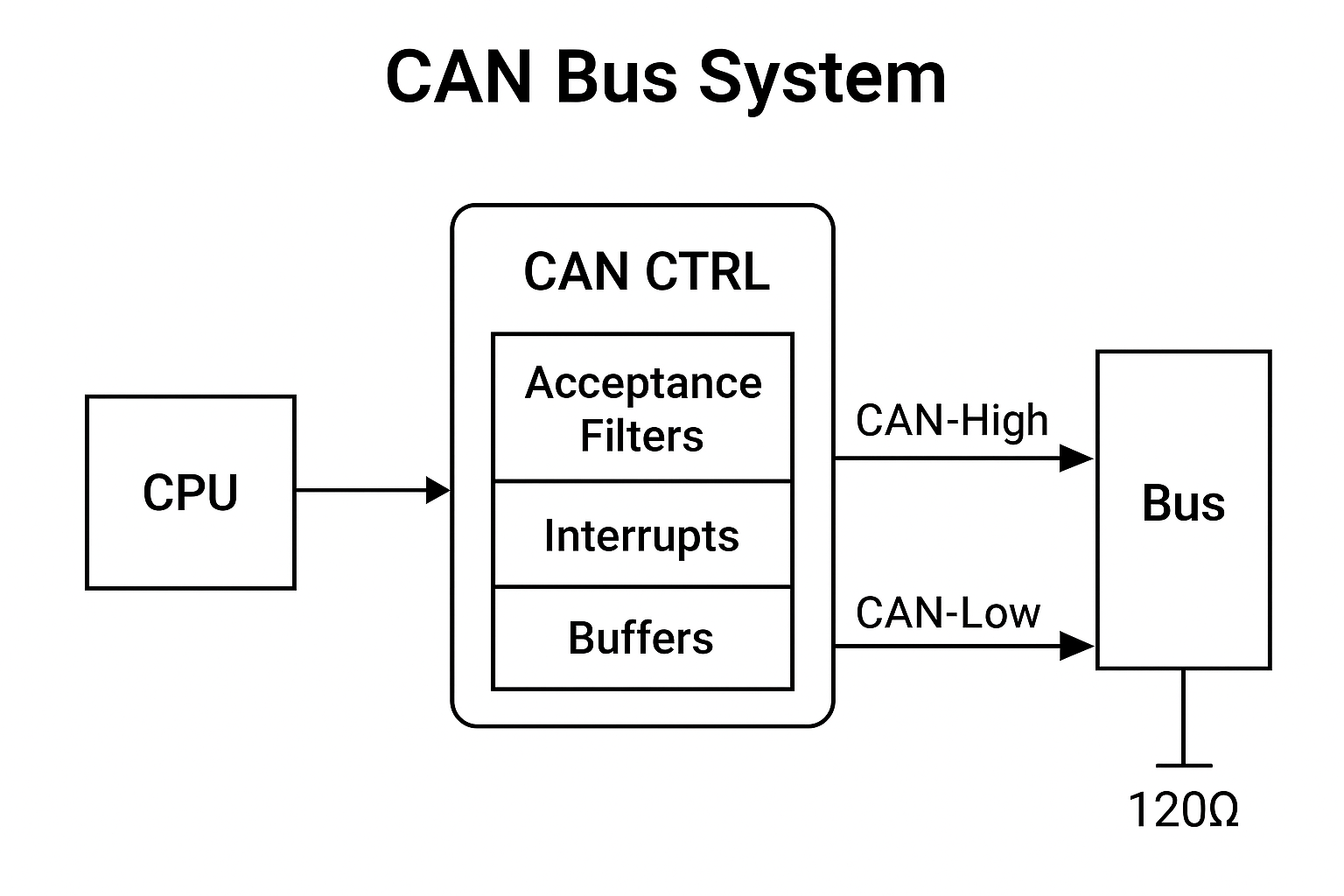
CAN Protocol Block Diagram — Overview
The CAN bus follows a multi-master bus architecture, which means that any node (or ECU) connected to the bus can send or receive messages at any time. It also has built-in error handling to keep communication reliable.
The main part of the CAN system is called the CAN core. This core acts like a memory-mapped device to the host processor and is responsible for sending and receiving CAN messages (called frames). It can be integrated easily with the host using standard interfaces like APB (Advanced Peripheral Bus) or AHB-Lite (Advanced High-performance Bus Lite), depending on performance and power needs.
Key Parts Inside the CAN Core
- Acceptance Filters: These help the system decide which messages should be accepted or ignored, making sure the ECU only processes relevant data.
- Interrupts: Programmable signals to alert the processor about new messages or errors.
- Buffers: Memory areas for storing messages before sending or after receiving.
- There are two types of transmit buffers:
- Primary Transmission Buffer (PTB): Holds high-priority messages.
- Secondary Transmission Buffer (STB): Stores lower-priority messages.
- Buffers work in a First-In-First-Out (FIFO) manner in priority mode.
- There are two types of transmit buffers:
CAN Bus Layered Architecture
The CAN communication protocol is defined by the ISO 11898 standard and has two main layers:
- Data Link Layer:
This layer manages how data is sent between nodes, error checking, and message prioritization. It has two sublayers:- MAC (Medium Access Control): Controls which node can use the bus at a given time and handles framing and error detection.
- LLC (Logical Link Control): Handles flow control, error recovery, and acceptance filtering.
- Physical Layer:
This layer defines how the data is physically transmitted over the wires — including voltage levels, timing, and connectors. It consists of:- PCS (Physical Coding Sublayer): Encodes and decodes the bits on the bus.
- PMA (Physical Medium Attachment): Handles framing and synchronization of bits.
- PMD (Physical Medium Dependent): Deals with actual transmission and reception of bits on the wire.
- MDI (Medium Dependent Interface): The physical connection to the network medium (cables).
How CAN Bus Works — Data Transmission and Arbitration
- CAN Frames:
Data is sent in packets called frames. Each frame includes a unique identifier (priority), control bits, data payload, and error-checking codes. - Multi-Master and Arbitration:
Multiple nodes can try to send data at the same time. To avoid collisions, CAN uses arbitration — a method that prioritizes messages with lower identifier numbers. The node with the highest priority continues to send, while others wait. - Bit Monitoring:
While sending data, each node listens to the bus to make sure the bit they sent matches what is on the bus. If not, it means another node has a higher priority message, so the lower priority node stops transmitting.
Example of Arbitration in the Architecture of the CAN Bus
Imagine two ECUs want to send messages simultaneously:
- ECU 1 has an identifier
0x234 - ECU 2 has an identifier
0x352
CAN uses wired-AND logic, meaning a dominant bit (0) overrides a recessive bit (1). When both ECUs transmit the third bit, ECU 1 sends 0 and ECU 2 sends 1. The bus reads 0 (dominant). ECU 2 detects the difference and stops transmitting, letting ECU 1 continue because it has higher priority.
Standard CAN Frame Format
Here’s what a typical CAN message frame looks like (in the standard 11-bit format):
| Field | Description |
|---|---|
| SOF (Start of Frame) | Indicates the beginning of a message (1 bit) |
| Identifier | Defines message priority (11 bits) |
| RTR (Remote Transmission Request) | Distinguishes between data and remote frames (1 bit) |
| Control Field | Contains user-specified flags |
| IDE (Identifier Extension) | Indicates if frame is standard (11-bit) or extended (29-bit) |
| DLC (Data Length Code) | Specifies number of data bytes (4 bits) |
| Data Field | Contains up to 8 bytes of actual data |
| CRC (Cyclic Redundancy Check) | Error-checking code (15 bits) |
| ACK (Acknowledgement) | Confirms correct reception (2 bits) |
| EoF (End of Frame) | Marks the end of the message (7 bits) |
Summary Architecture of the CAN Bus
| CAN Bus Element | Description |
|---|---|
| Nodes (ECUs) | Devices with MCU, CAN controller, and transceiver |
| CAN-High and CAN-Low | Twisted pair differential signaling wires |
| Termination Resistors | 120 Ω resistors at bus ends to prevent reflections |
| Physical Layer (ISO 11898-2) | Defines wiring and signaling specifications |
| Data Link Layer (ISO 11898-1) | Manages message framing, arbitration, and error handling |
| Arbitration | Priority-based bus access control |
Conclusion
The CAN bus system is a simple yet powerful communication protocol enabling multiple devices to communicate over a shared two-wire bus efficiently. Its architecture combines robust physical wiring, standardized messaging, and smart arbitration techniques to ensure data integrity in noisy environments like vehicles. Understanding its basic components and working principle is essential for anyone diving into embedded systems or automotive electronics.
1. What is the CAN bus system?
The CAN (Controller Area Network) bus system is a robust communication protocol used primarily in automotive and industrial applications to allow microcontrollers and devices to communicate with each other without a host computer. It enables multiple nodes to share data efficiently over a single two-wire bus.
2. How is the architecture of a CAN bus system structured?
The CAN bus architecture consists of several nodes connected through a twisted pair cable. Each node contains a CAN controller and a transceiver. The controller manages data framing, error checking, and message filtering, while the transceiver converts the controller’s digital signals to differential signals for the bus.
3. What are the main components of a CAN node?
A typical CAN node has three main parts: the microcontroller (which runs the application), the CAN controller (which handles CAN protocol functions), and the CAN transceiver (which interfaces with the physical bus).
4. What type of bus topology does CAN use?
CAN uses a multi-master, broadcast communication bus topology. This means any node can start transmitting data when the bus is free, and messages are broadcast to all nodes simultaneously.
5. How does CAN handle message priority?
CAN uses message identifiers to determine priority. Lower numerical values of identifiers have higher priority on the bus, allowing critical messages to get transmitted first during bus arbitration.
6. What is bus arbitration in CAN?
Bus arbitration is the process by which multiple nodes attempt to transmit data simultaneously. CAN uses a nondestructive arbitration method based on message priority, ensuring the highest priority message gains bus access without data loss.
7. How does CAN ensure data integrity and error handling?
CAN includes several error detection mechanisms such as CRC (Cyclic Redundancy Check), bit stuffing, acknowledgment checks, and error flags. When an error is detected, nodes retransmit messages to maintain data reliability.
8. Why is CAN preferred in automotive systems?
CAN is highly reliable, efficient, and cost-effective. It supports real-time communication with robust error handling and allows many electronic control units (ECUs) to communicate over a simple two-wire bus, making it ideal for automotive applications.
9. Can CAN bus systems support long distances and high speeds?
CAN supports data rates up to 1 Mbps and bus lengths typically up to 40 meters at the highest speed. For longer distances, the speed is reduced to maintain signal integrity.
10. What is the difference between CAN 2.0A and CAN 2.0B?
CAN 2.0A supports standard frames with 11-bit identifiers, whereas CAN 2.0B supports extended frames with 29-bit identifiers, allowing for more message identifiers and better flexibility.
You can also Visit other tutorials of Embedded Prep
- Multithreading in C++
- Multithreading Interview Questions
- Multithreading in Operating System
- Multithreading in Java
- POSIX Threads pthread Beginner’s Guide in C/C++
- Speed Up Code using Multithreading
- Limitations of Multithreading
- Common Issues in Multithreading
- Multithreading Program with One Thread for Addition and One for Multiplication
- Advantage of Multithreading
- Disadvantages of Multithreading
- Applications of Multithreading: How Multithreading Makes Modern Software Faster and Smarter”
- Master CAN Bus Interview Questions 2025
- What Does CAN Stand For in CAN Bus?
- CAN Bus Message Filtering Explained
- CAN Bus Communication Between Nodes With Different Bit Rates
- How Does CAN Bus Handle Message Collisions
- Message Priority Using Identifiers in CAN Protocol


Mr. Raj Kumar is a highly experienced Technical Content Engineer with 7 years of dedicated expertise in the intricate field of embedded systems. At Embedded Prep, Raj is at the forefront of creating and curating high-quality technical content designed to educate and empower aspiring and seasoned professionals in the embedded domain.
Throughout his career, Raj has honed a unique skill set that bridges the gap between deep technical understanding and effective communication. His work encompasses a wide range of educational materials, including in-depth tutorials, practical guides, course modules, and insightful articles focused on embedded hardware and software solutions. He possesses a strong grasp of embedded architectures, microcontrollers, real-time operating systems (RTOS), firmware development, and various communication protocols relevant to the embedded industry.
Raj is adept at collaborating closely with subject matter experts, engineers, and instructional designers to ensure the accuracy, completeness, and pedagogical effectiveness of the content. His meticulous attention to detail and commitment to clarity are instrumental in transforming complex embedded concepts into easily digestible and engaging learning experiences. At Embedded Prep, he plays a crucial role in building a robust knowledge base that helps learners master the complexities of embedded technologies.